Project 1
FINAL PROJECT 14A
AIM:- To develope model of any three topologies from the below 14 topologies.
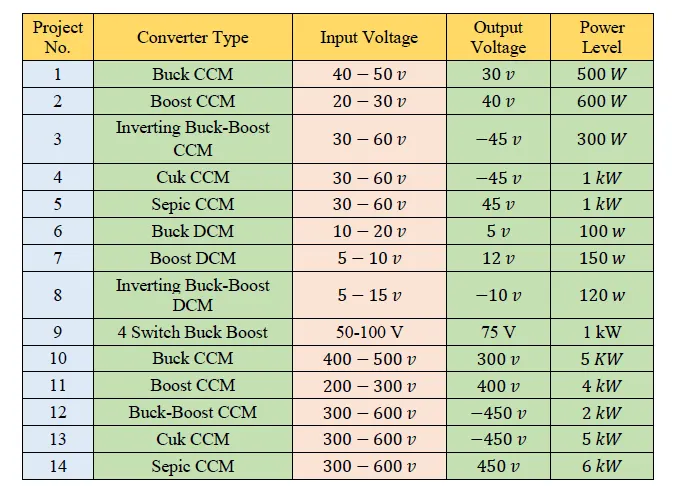
Here i will choose the following three topologies as per my choice.
- Buck converter in CCM. (500W)
- Boost converter in CCM. (600W)
- Cuk converter in CCM. (5000W)
500w Buck converter in CCM
In buck converter we are getting the output voltage less than the input voltage
with same power on input and output side.
Here thge given parameters are.
Input voltage Vin = 40 - 50V
Output voltage Vout = 30V.
Power P = 500W
we will assume the switching frequency as Fs = 200Khz.
First we will calculate the range of Duty cycle D .
if Vin = 40v, D = Vout/Vin = 30/40 = 0.75
if Vin = 50v , D = Vout/Vin = 30/50 = 0.6
So, Range of D is
0.6<=D<=0.75
Now, we will Take the input voltage as 45 V
D(45) = Vout/Vin = 30/45 = 0.67
Inductor current Il = P/Vout = 500/30 = 16.67A
R = Vout^2/P = #0^2/500 = 1.8ohm
I will design the inductor for 1% ripple, so
Delta Il = 1*Il/100 = 0.1667A
=> L = Vout(1-D)/Fs*Delta Il
L = 30(1-0.67)/200Khz*0.167
L = 0.2964mH = 29.64e-4
Also
We will design the caoacitor of 20% rippel as
Delta Vout = 20*Vout/100 = 6
=> Delta Vout / Vout = 6/30 = 0.2
Cout = (1-D)/8*L*Fs*(Delta Vout/Vout)
Cout = 1.75e-5mF = 1.75e-8 F
Now we will build the model in Simulink as
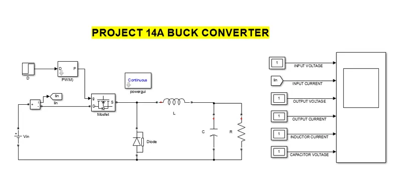
The necessery waveforms of Component current and voltages are as. (Zoomed out)
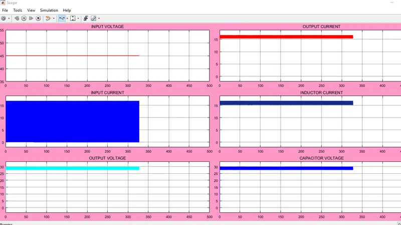
Zoomed in
600w BOOST converter in CCM
In boost converter we are getting the output voltage higher than the input voltage
with same power on input and output side.
Here thge given parameters are.
Input voltage Vin = 20 - 30V
Output voltage Vout = 40V.
Power P = 600W
we will assume the switching frequency as Fs = 200Khz.
First we will calculate the range of Duty cycle D .
if Vin = 20v, D = (Vout-Vin)/Vout =(40-20)/40 = 0.5
if Vin = 30v , D = (Vout-Vin)/Vout =(40-30)/40=0.25
So, Range of D is
0.25 <= D <= 0.5
Now, we will Take the input voltage as 25 V
D(25) = (Vout-Vin)/Vout =(40-25)/40=0.375
Load R = Vout^2/P = 40^2/600 = 2.67ohm
Inductor current (Il) = Vin/R(1-D)^2 = 23.97A
Now we will design the inductor with 20% ripple
Delta (Il) = 20*Il/100 = 4.79A
L = Vin/(Fs*Delta(Il)) = 25/200Khz(4.79) = 0.02609mH = 2.069e-5 H
Also we will design a capacitpr with 1% ripple as
Delta (Vout) = 1*Vout/ !00 = 0.25
Also Delta(Vout)/Vout = 0.0025
Cout = D/(R*Fs*(DeltaVout/Vout)) = 0.2808mF = 28.089F
Now we will design the boost converter in Simulink as
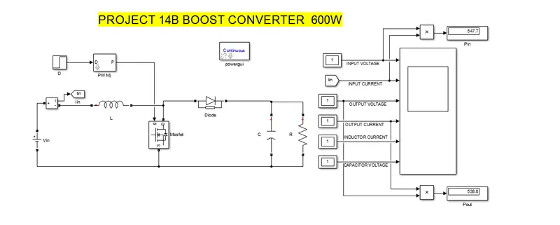
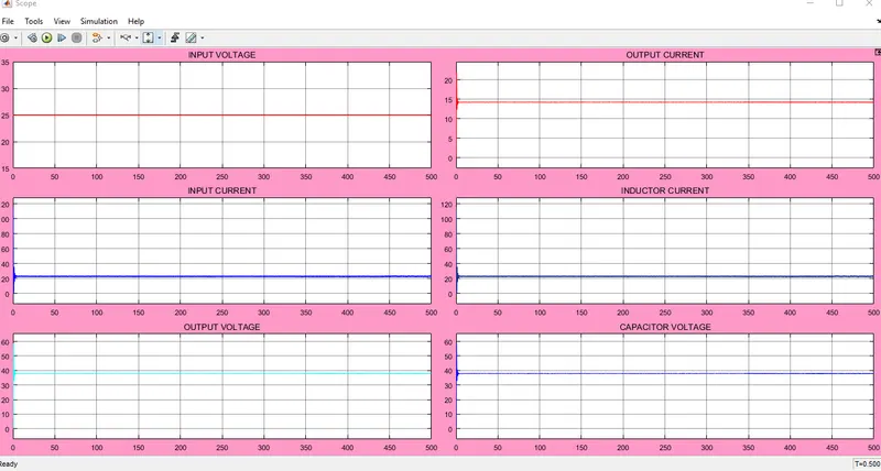
The nacessery output input and component current and voltage waveforms are as
(Zoomed out)
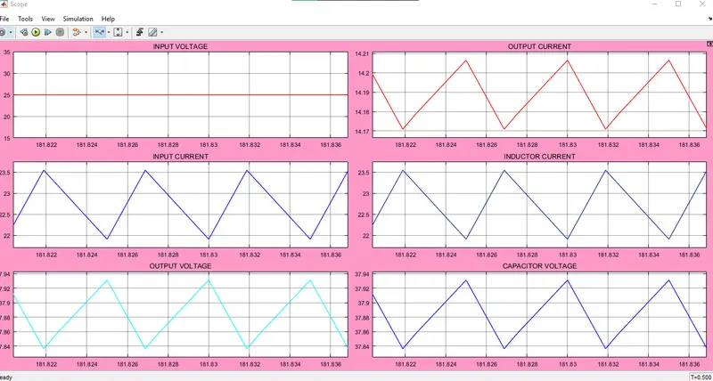
Zoomed in
5000W CUK converter in CCM
A CUK converter transforms a DC voltage at the input to a DC voltage at the output
with reversed polarity. Compared to the Buck, Boost and Buck-Boost converters the CUK
converter uses an additional inductor and capacitor to store energy.
Here thge given parameters are.
Input voltage Vin = 300 - 600V
Output voltage Vout = -450V.
Power P = 5000W
we will assume the switching frequency as Fs = 200Khz.
First we will calculate the range of Duty cycle D .
if Vin = 300v, D = Vout/(Vout-Vin)=-450/(-450-300) = 0.6
if Vin = 30v , D = Vout/(Vout-Vin)=-450/(-450-600) = 0.4285
So, Range of D is
0.4285 <= D <= 0.6
Now, we will Take the input voltage as 500 V
D(500) = Vout/(Vout-Vin)=-450/(-450-500) = 0.473
Now the value of Currents in inductors.
Il1 = Iin = P/Vin = 5000/500 = 10A
Il2 = Iout = P/Vout = 5000/-450 = -11.11A
R = Vout^2/P = -450^2/5000 = 40.5ohm
Lets design the CUK inductors at 1% ripple
Delta(Il1) = Il1*1/100 = 0.1A
Delta(Il2) = Il2*1/100 = 0.11A
Now
L1 =D*(Vin/Fs*Delta(Il1)) = 11.825mH = 0.011825H
L2 =D*(Vin/Fs*Delta(Il2)) = 10.65mH = 0.01065H
We need to find the Cap. C1 voltage for Capacitor calculation as
Vc1 = Vin - Vout = 500-(-450) = 950V
We will design the capacitors for 20% ripple
Delta (Vc1) = 20*Vc1/100 = 190v
now C1 = (Vout*D)/(R*Fs*Delta(Vc1)) = 0.000138mF = 1.383F
Also we will design Cout for 20% ripples as
Delta (Vout) = 20*(Vout)/100 = 90
Delta (Vout)/Vout = 90/450 = 0.2v
Cout = (1-D)/(8*L2*Fs*(Delta (Vout)/Vout)) = 7.65e-7mF = 7.65e-10F
Now we will design the Cuk converter in Simulink as.
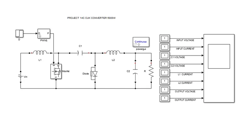
Nacessery waveforms of input, output, Component current and voltage as (Zoomed out)
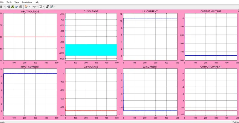
Zoomed in
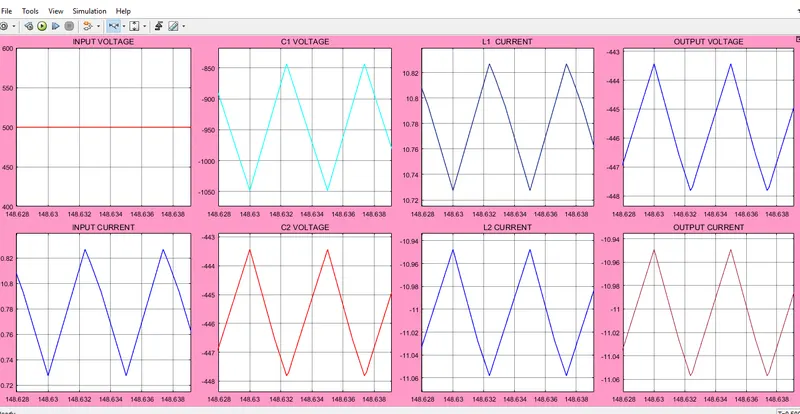
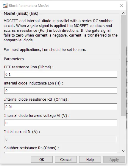
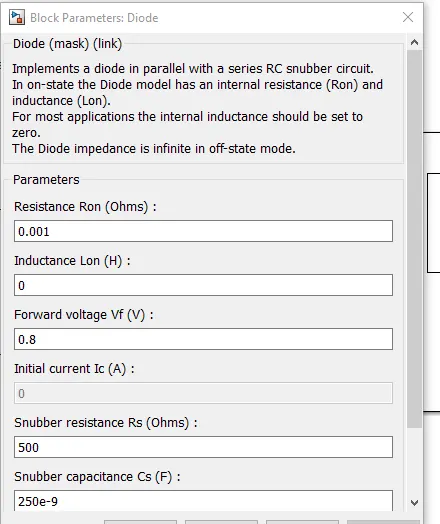
Now i will show you the Description of few commenly used components used in these converters.
MOSFET USED
DIODE USED
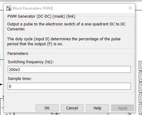
PWM GENERATOR USED
That is all for the project 14
Kindly find the attached .mdl files below.
------------------------------------------END-----------------------------------------------------