Project 2
AC DC converters, Harmonics and related standards
Final project
Part A
AIM:- Design a DC power supply using PFC circuit for general purpose applications with 350V dc
output and load in the range of 0-7A. The supply should meet the harmonic standard limits for input
power quality such that current THD limits are satisfied with input power factor >0.97 value.
The input side is connected to single phase grid with parameters as 230V, 50Hz.
Design the supply to give following specifications:
- Component selection and justification
- Passive component designs including filters
- Controller design
- Simulation results
- Validation with the design criterion
Redesign the above power supply with the PWM rectifier. Give the difference in both power supplies
in terms of cost, control complexity, degrees of freedom, additional features and efficiency.
Here will design the DC power supply in Matlab simulink with power factor correction from
the given data.
- Power output max = 2450W
- Output DC voltage = 350V
- Input AC voltage = 230V, 50Hz
- power factor >= 0.97
The components used in the model will be calculated using a Matlab script file which will be
attached with the submission, the calculated parameters from the script file is as.
PsMax = 2.6316e+03 W Maximum power drawn from source
IinMaxRms = 13.1579 A
IinMaxPeak = 18.6081 A
IinMaxAvg = 11.8463 A
Cin = 3.4902e-07 F
VinMinPeak = 282.8427 V
Dpeak = 0.1919
DIL = 3.7216 A
ILMaxPeak = 20.4689 A
L = 1.2152e-04 H
Co = 0.0011 F
Based on the above calculated parameters we will choose the following Diodes for REctifier
boost PFC, and Switch for the Boost stage.
For the boost stage we will use an international rectifier product with part number IRF740
it has the following features.
- Vds = 400V
- Vgs = 10V
- Rds on = 0.55ohm
- Continues Id = 10A
- Pulsated Id = 40A
Rest of the details could be found from the datasheet Which will be attached below.
Also the Diode used foe rectifier stage are selected from international rectifiers with
part number 15ETH06 which has the following features.
- Trr = 22ns #ultra fast
- If Avg = 15A
- Vr = 600V
- Peak surge current non repeative = 120A
Others details for this diode can be found from the datasheet which willbe attached below.
The matlab simulink model for this project is shown below.
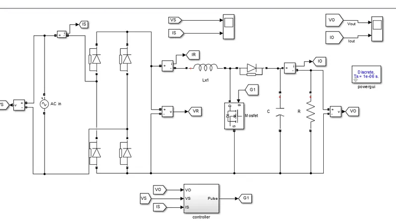
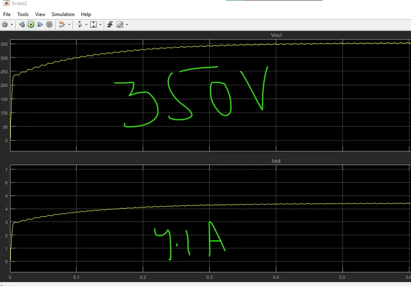
Here we have used the Boost type PFC so the power factor will be near unity,the output voltage
and current waveforms will be like .
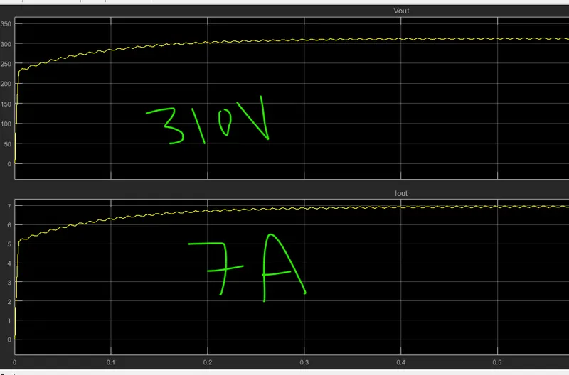
Also if we increase the load to rated power, the voltage will be decreased to some extent as shown
in below waveform.
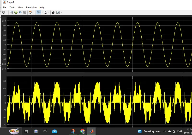
Also the input voltage and current waveform will be look like.
Now we will redesign the same model using the PWM technique, In this model we will use
four fully controllable switches (IGBT's) , The IGBT's used are From STM electronics with
part number STGB19NC60KD It has the following properties.
- Vce = 600V
- Ic = 35A @25'c and 20A @100'C
- Ic pulsed = 75A
- Vge = +-20V
Other details for this module can be found from the datasheet which will be uploaded below.
Now the matlab simulink model for this will be as shown below.
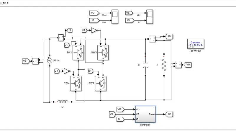
Here we are using the same controller technique as that of previous one with a sligh change ,
here SWi and SW2 are getting the direct pulses and SW3 and SW4 have the same pulse through
a not Gate.
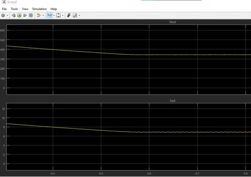
The output voltage and current waveforms are as shown below.
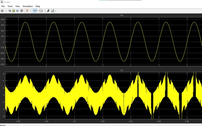
Also the input voltage and current waveforms are as shown below.
Part B
AIM:- Design a high-performance high voltage DC power supply for 15 kV dc output and load in
the range of 0-10A. The supply should meet the harmonic standard limits for input power quality
such that current THD limits are satisfied with input power factor >0.98 value. The input side is
connected to three-phase LV grid with parameters as 11kV (line-line), 50Hz.
Design the supply to give following specifications:
- Component selection and justification
- Passive component designs including filters
- Controller design
- Simulation results
- Validation with the design criterion
Here we will desigb a simulink model based on the following parameters.
- Power = 150Kw
- Input AC voltage = 3 phase 11Kv, 50Hz
- Output DC voltage = 15KV DC @10A
Here we will calculate the Component values from a matlab script which is attached at the end.
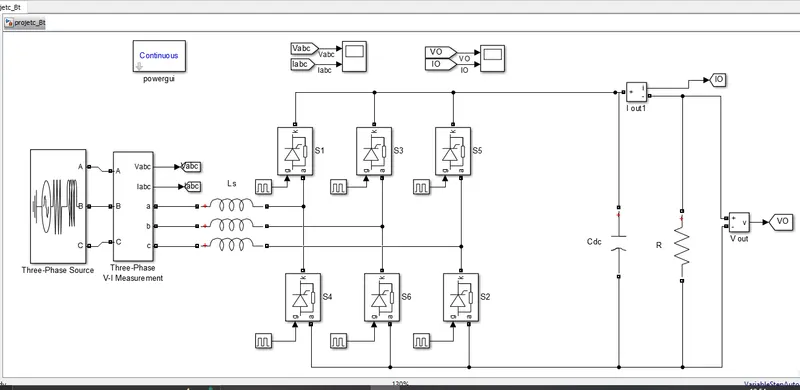
Also we have selected the Thyridtor for this model from IXYS manafactures with the part
number MCC312 which has the following features.
- Itrms = 1040A
- Itavm = 640A
- Vrrm = 1200-1800V
We will use multiple Thyristors in series to meet trhe model requirements.
other detailed features for this product can be found from its datasheet which will be attached
below.
after this we will build the simulink model as shown below.
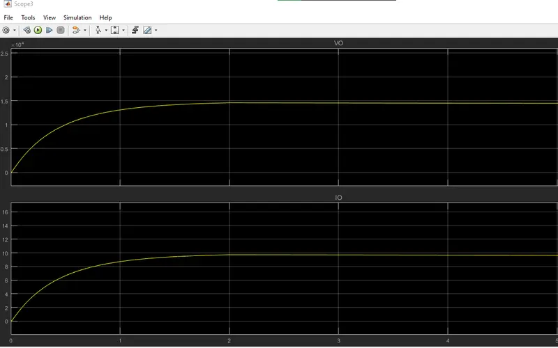
The output voltage and current will be as.
PFA model files. and datasheets