Project 1 - Loss calculation for a DC/DC converter-MATLAB
PROJECT 01
AIM:- Design of boost converter, and calculating the loss of different components including
power switching device and deriving efficiency of boost converter. This is applicable in power
supply industry, electric vehicles etc where DC-DC converter is required to boost the voltage
from DC source. All the aspects of this project with loss calculation, device selection, simulation
etc are industry relevant.
For this project i will design a BOOST Converter with the following parameters.
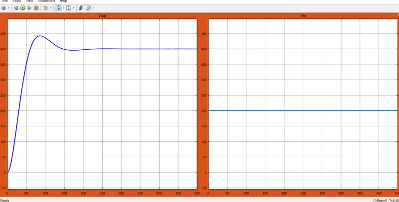
- Input voltage 200V
- Output voltage 400V
- Power 2Kw
Based on these parameters we will calculate the Duty cycle, Inductor (20% Ripple)
and Capacitor (5% ripple).
We know Foe a boost converter Duty cycle an be calculated as.
Vout/Vin = 1/(1-D)
=>D = (Vout-Vin)/Vout
D = (400-200)/400
D = 0.5
We will choose the switching frequency as 50KHz = FS
Load resistance will be calculated as
RL = Vout^2/P
RL = 400^2/2000
RL = 80ohm.
IL = vout/(1-D)*R
IL = 400/(1-0.5)*80
IL = 20A
We will design the Inductor for our converter with 20% ripple
=> delta(IL) = (IL/100)*20
delta(IL) = (20/100)*20
delta(IL) = 4A
=> L = (Vin)/Fs*delta(IL)
L = (200)/50KHz*4
L = 0.5mH
L = 50e^-3 H
Also we will the Converter Capacitor with 5% ripple voltage
delta(Vout) = 5*(Vout/100)
delta(Vout) = 5*(Vout/100)
delta(Vout) = 20V
also delta(Vout)/Vout = 20/400
delta(Vout)/Vout = 0.05V
C = D/(R*Fs*(delta(Vout)/Vout ))
C = 0.5/200
C = 0.0025mF
C = 2.5e^-6F
Now we have all the parameters Calculated , we will consider the followinf resistances for loss calculations
rL = 5*10^-3 ohm #Inductor resistance
rC = 5*10^-3 ohm #Capacitor ECR
rMOSFET = 1*10^-3 ohm # Mosfet internal resistance
rDIODE = 1*10^-3 ohm # Diode R on resistance
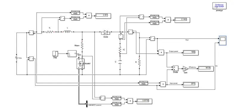
By considering these parameters we will build a simulink model as shown below.
Simulink model for Boost converter
Input and Output voltage waveforms
The above simulink model of boost converter has a Effeciency of 96%
Now we will consider the losses which are present in the converter like the Mosfet loss
Diode loss, Inductor loss due to its internal resistance od coil, Capacitor ECR loss.
These losses are in direct relationship with the duty cycle. When the integrated
high-side MOSFET turns on, the load current flows through it. The drain-to-source channel
resistance (RDSON) causes power dissipation, which can be expressed as.
Pmosfet = (Iout^2)*Rdson*D
Where D = Duty cycle =0.5 Calculated
Losses in Diode are given as
Pdiode = Vf*Iout*(1-D)
Vf = Forword voltage drop in diode here in this case i have considered 0.2V
there are conduction losses in the inductor as well because every inductor has a finite DC
resistance (DCR), which is the resistance of the wire in the coil. Equation 3 expresses the
dissipation in the inductor as:
Pind = (Iout^2)*DCR
Losses in Capacitor ESR is given as
PcapESR = Vesr*Iesr
The conduction losses depend on the load current. With heavier loads, the conduction
loss in the MOSFET increases and is the dominating factor. Conduction losses plus switching,
driver and internal low-dropout regulator (LDO) losses lead to a considerable generation of
heat and increase the junction temperature of the integrated circuit (IC). Equation 4
expresses the increase in junction temperature as:
ICtj = (ICpd*Qja) + Ta
here ICTj is the junction temperature of the IC, TA is the ambient temperature, θJA is the
junction-to-air thermal resistance and ICPd is the total power dissipation just in the IC
equal to . The RDSON of the MOSFET typically has a temperature coefficient (RdsonTco).
With an increase in the junction temperature of the IC, the RDSON would increase above
the nominal based on the temperature coefficient. While this parameter may not be
available in the data sheet, TI’s WEBENCH® Power Designer software has that
information and uses it for calculating the design efficiency, thus making the results
accurate. Equation 5 can adjust the RDSON based on the junction temperature:
Rdson = Rdsonnom+(ICtj-Ta)*Rdson
where RdsonNom is the nominal value of RDSON
Pconduction loss = Pmos+Pdiode +Pcap+Pinductor
Ptotal = Pconduction + Pdriver LDO + Psw
Effeciency = Pout/(Pout+Ptot)