Project - Speed Control of a Direct Current (DC) motor
Simulink Basics Final project;
Title of project:- DC Motor modelling with PID Controller
For the model i will consider the values as of training part
to avoid any errors.
Moment of inertia (J) = 0.01Kgm^2
Motor viscus friction (B) = 0.1 Nms
Emf constant (Km) = o.o1 V/Rad/S
Motor torque constant (Km) = 0.01 Nm/Amp
Armature resistance (Ra) = 1.0 Ohm
Armature indictance (La) = 0.5 Henry
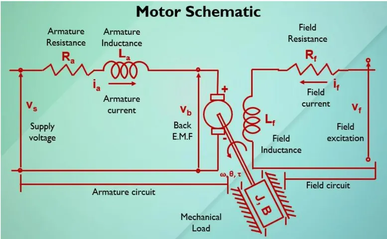
From the moter schematic Shown above we have the following equations
i have written simply La=L, Ra=R,Vs=V,Ia=I,KbW=Vb,
L(dI/dt) + RI = V - Kb*W .... (1) From KVL
J(d^2Q/dt^2) + B(dQ/dt) = Kt*I .....(2) From newtons law
Now transforming these equatioins to Laplace domain we have
Ls*I(s) + R*I(s) = V(s) - Kbs*Q(s)
=> I(s) ={ V(s) - KbsQ(s) }/ Ls+R ..... (3)
Js^2*Q(s) + Bs*Q(s) = Kt*I(s) .....(4)
W(s) = s*Q(s) = Kt*I(s)/J(s)+B ....(5)
Putting the values of I(s) in eqn (4) we get
Q(s)/ V(s) = Kt/s{(Ls+R)(Js=B) + Kt*Kb}
OR
W(s)/V(s) = (Ls+R)(Js=B) + Kt*Kb
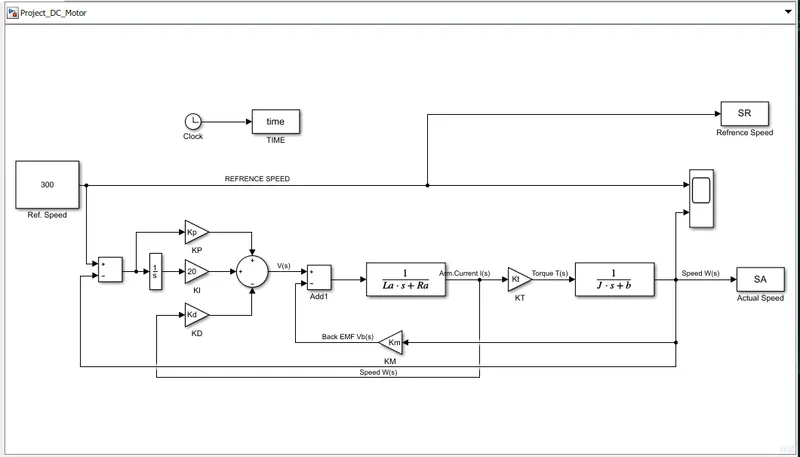
To Find Gains KP and KD please find the attachment script file.
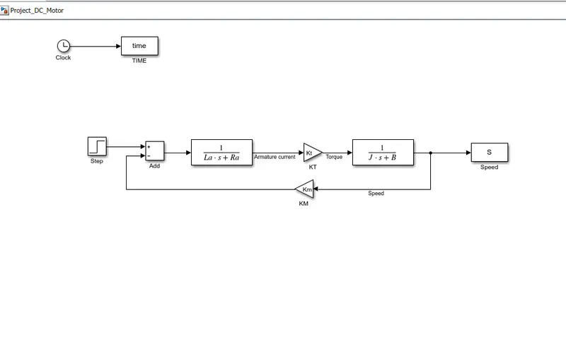
After this we will build the simulink model as shown below
Model with no PID controller
MODEL WITH PID CONTROLLER
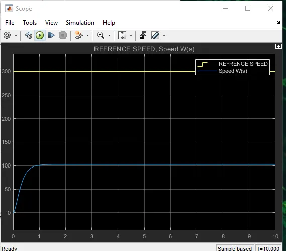
Plot at KI = 0
Plot at KI = 10
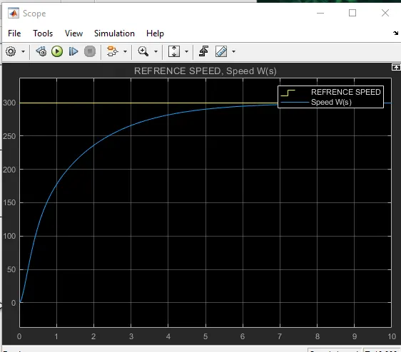
Plot at KI = 20
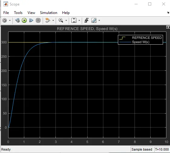
Plot at KI = 30
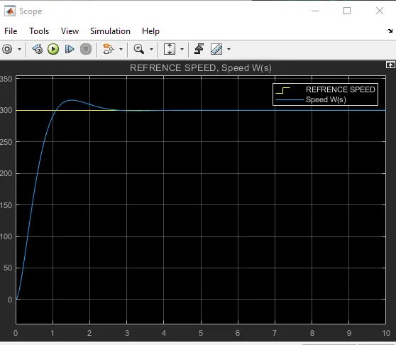
By checking the plots we can thay that The more speed control is at KI = 20
PLease find the attachment files below.