Project 2
1.Develop general arrangement for the RC office building. Analyze and design the building as per IS standard code in TEKLA STRUCTURAL DESIGNER. Refer the attached plan and elevation. The building to be designed for dead, live, wind and seismic loading.
Report of each member to be generated and extract drawings for structural plans, beam reinforcement details from the software.
Ans)
Aim: To setup model for RC building design and based on following parameters for cover.
Tools Required:
-> Tekla model
->File Menu
-> Attachments
-> Paint Tool
-> Settings
->Construction Levels
-> Girds
->Parallel (quick)
->Properties
->Structural Defaults
->Levels
-> Manage Properties -> New -> Members -> Concrete Column.
-> Concrete Beam
-> Slab
->Beams
->Columns
->Interactive Design
->Static
->Slab
->Foundations
->Check panel
->Catalogue
->Design pile cap foundation
Procedure:
- Firstly, open the new file.
- Now under the file menu select the settings option.
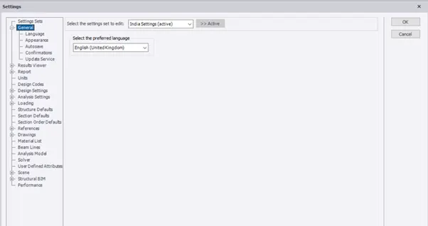
- A dialogue box will appear on the screen.
- Now select the structural defaults and sets all the values as per our requirement.
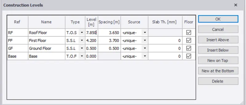
- Now under the structures option select the construction levels and mane them and give the spacing as per the attachments.
- Now click on model tab and select the grid option.
- Now with the help of that option draw a grid line and keeping that as reference draw the remaining grid lines.
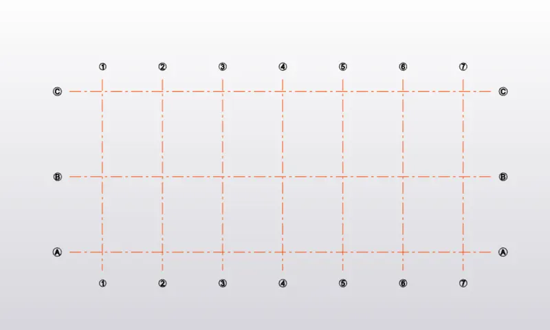
- Let the vertical grids spacing be 6.000 and horizontal be 8.500 and 7.500.
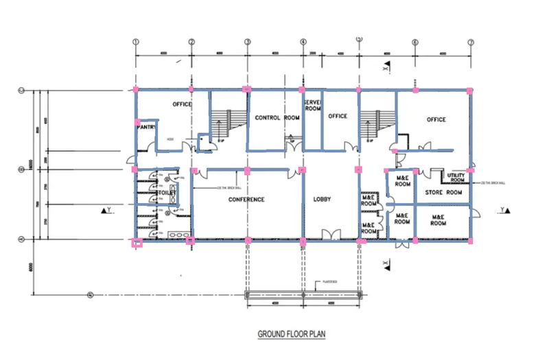
- Now with the help of paint window draw the rough sketch of Columns and beams.
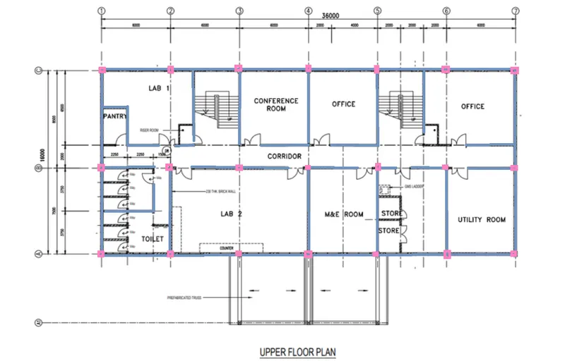
- Now click on the levels option which is present at the right side of the display and you will be directed to a new dialogue box where in you have to assign the levels accordingly as show in the picture give below with its respective values, later click ok.
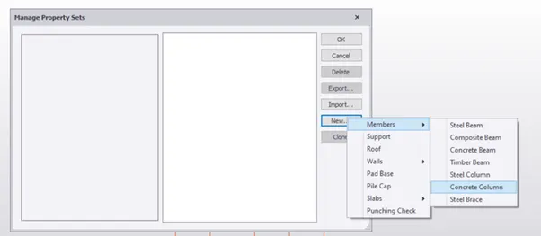
- Now select the manage properties option and again you will be directed to a new dialogue box where in you have to select and create a new member of concrete column naming it as CC1 assign the values as per our requirement in the general tab.
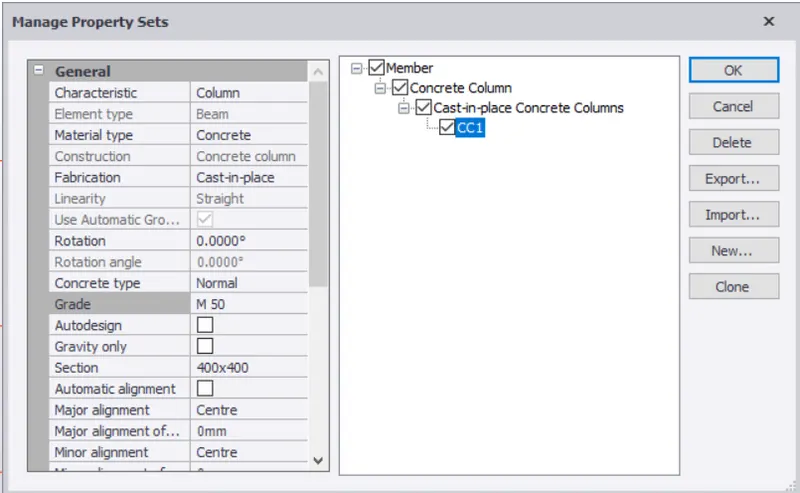
- Now you can also edit the other values like the length and width also the shape of the column and many more.
- After all the settings are done click ok.
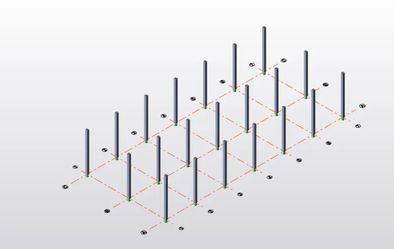
- Now you can see the grids file that is open on your project workspace now select on column that is present under the model tab.
- Now you can see that there are properties of the column displayed at the properties bar although you have modified the properties but its good to go for a check for you to feel everything is according to our requirement.
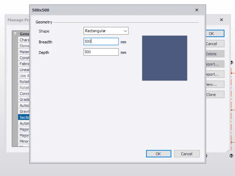
- Now according to the attachments place the columns in their respective places.
- In the same way following the above procedure for the concrete beams and slab as well.
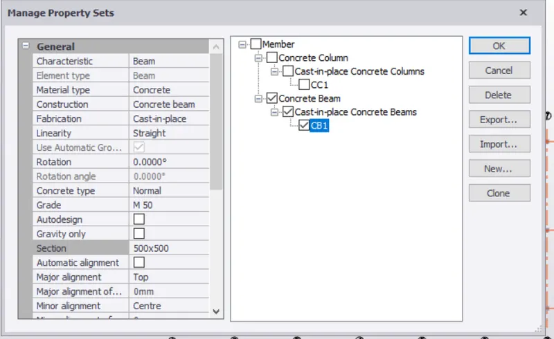
- By naming the concrete beam as CB1 and slab as S1.
- Also design the staircase with the proper adjustments.

- To create staircase we need to select the components and make them all come under a substructure naming it as staircase.
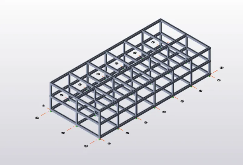
- Now add the slope with the help of sloped plane option.
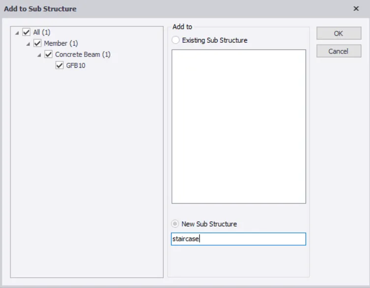
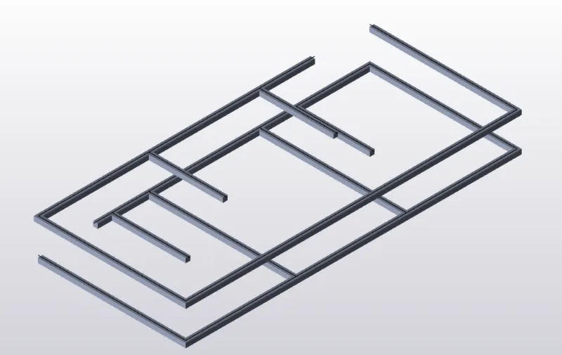
- Now create slab for the entire structure.
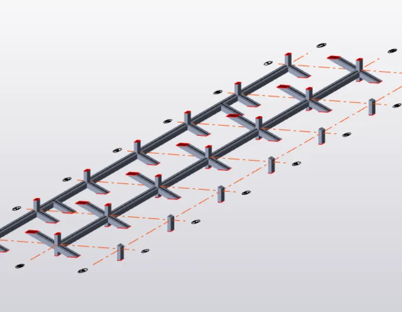
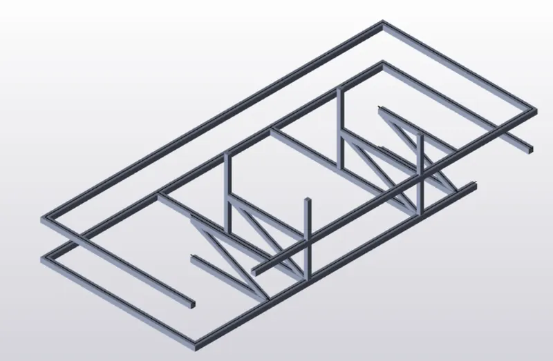
- Now create slab of overall depth 900mm and with grade M50.
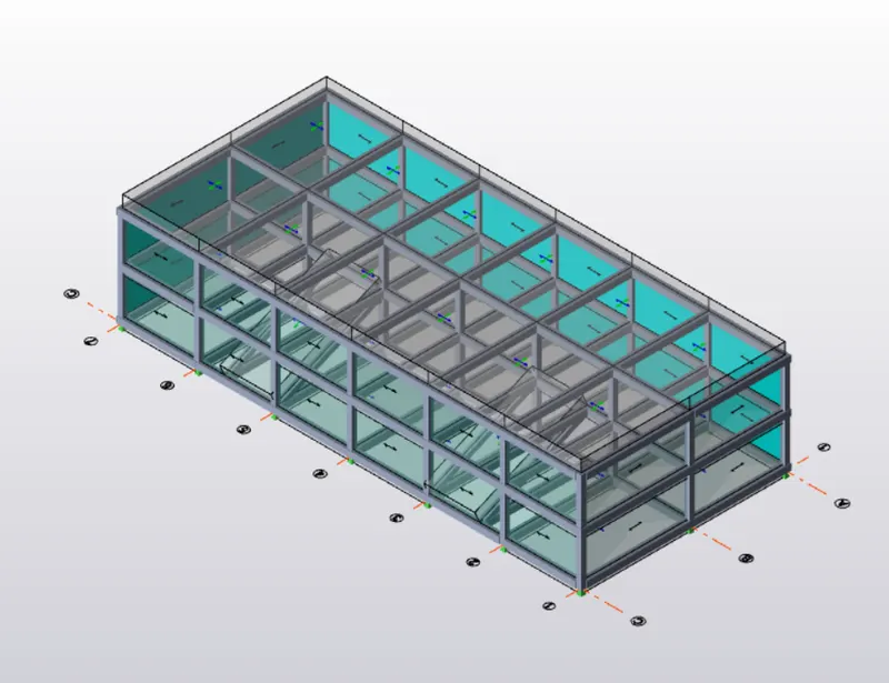
- Check weather thr include in diaphram is off while adding slab for staircase.
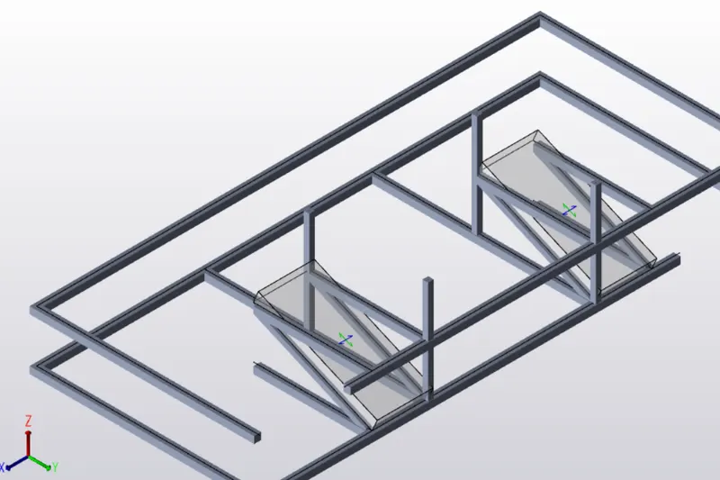
->To design dead, live, wind and seismic loading for The structure.
Calculations:
DEAD LOAD :
Slab load = Model slab in software.
Finishes loading (10THK) = 0.01m x 24 KN/m^3 = 0.24 KN/m^2.
Brick wall with cement plaster thickness = 150mm.
Unit weight = 20 KN/m^3
Floor height (GF to FF) = 3.7 m
Brick wall loading = 11.1 KN/m
Floor height (FF to Roof) = 3.65 m
Brick wall loading = 10.95 KN/m
Roof loading = 0.22 KN/m^2
Procedure:
- Go to load tab and select load cases option under that, Load cases dialog box appears.
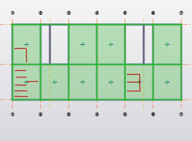
- Under load tab we have to select area and give the value of 1.2KN/m square, and select all the slabs.
- Now we have to select Full UDL and apply the dead load to all the beams.
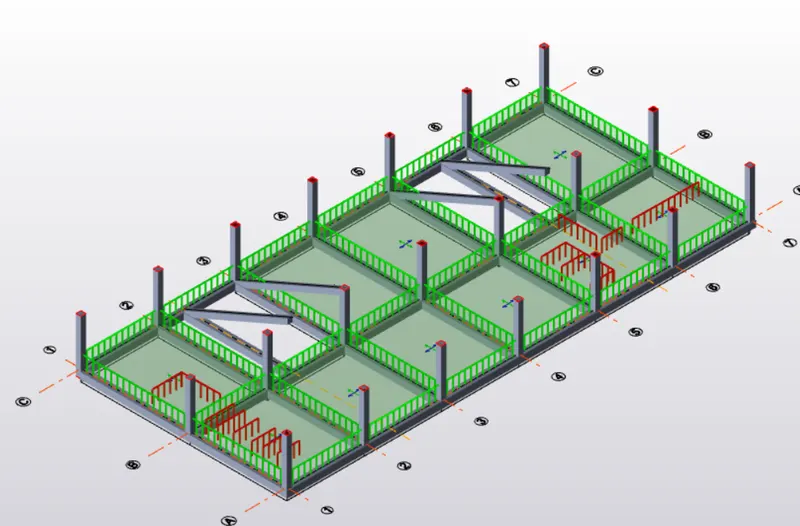
- Now select Line tool under load tab and draw the walls load in all the required floors.
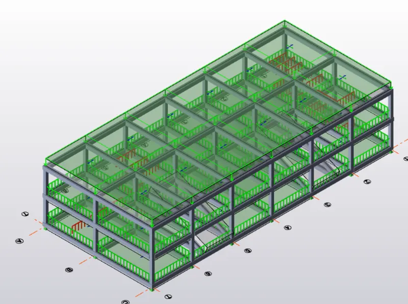
- Now at the bottom of our workspace we find imposed load option in the drop up dialog box.
- Now we can provide live loads to the structure by selecting the load and assigning the value for it according to the IS Code.
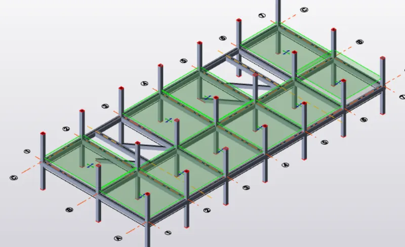
- Click on loads icon and select area option under that.
The LIVE LOAD for the structure can be obtained from the IS building standard codes.
- Now under the property dialog box enter the required load for different room.
Store room = 5 KN/m^2
Staircase = 5 KN/m^2
Office = 3 KN/m^2
Rest room = 2 KN/m^2
Meeting Room = 2 KN/m^2
Toilets = 2 KN/m^2
Pantry = 3 KN/m^2
Corridor = 4 KN/m^2
Equipment room = 10 KN/m^2
- Now set the loads with different values and apply them by clicking on the respective slabs.
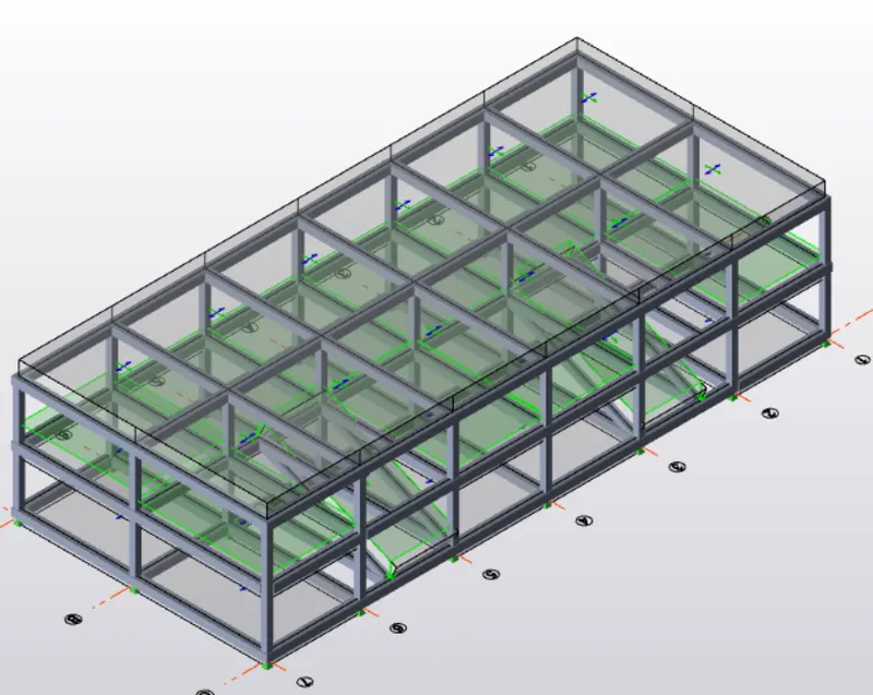
- Now repeat the same process for all the remaining levels that is for the first and to top of the roof also.
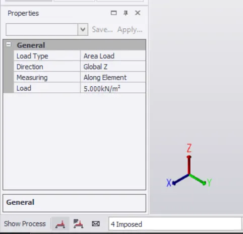
SERVICE LOAD CALCULATION:
Water tank = 10 KN/m^3 x 2m = 10 KN/m^2
WIND LOAD CALCULATIONS:
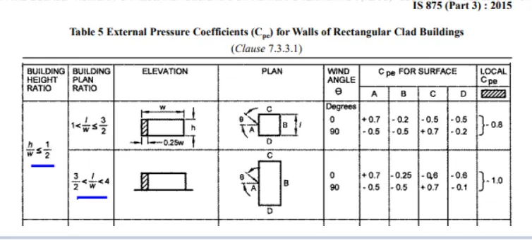
- Now take the dimensions of the model such as height, length, width etc.
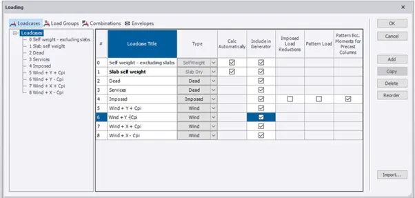
- Now place the values in the Microsoft Excel Worksheet and type the required content.
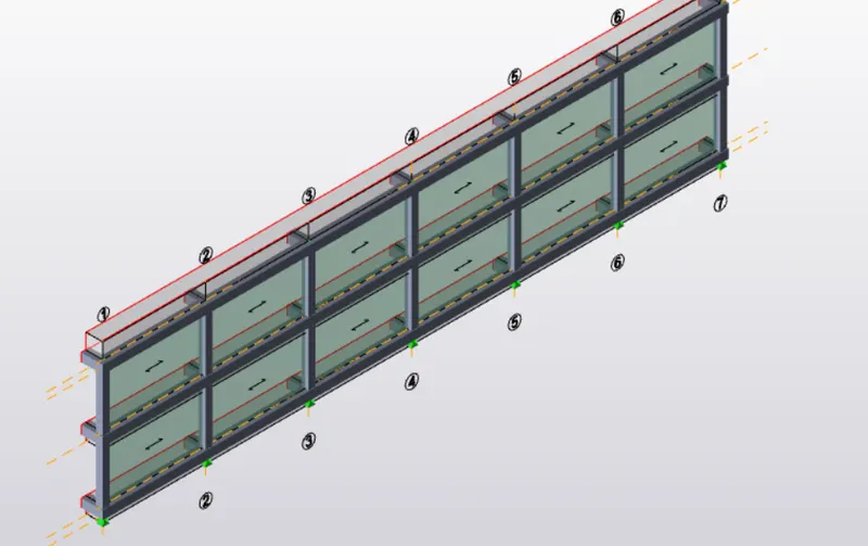
- Multiply the factors as in when required.
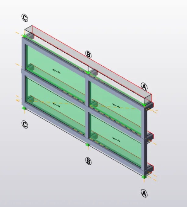
|
Wind load calculations as per IS: 875 P3-1987 |
|||||||||||
|
Basic parameters |
|||||||||||
|
Basic wind speed Vb= |
50 |
m/s |
Terrain category= |
2 |
|||||||
|
Probable design life= |
50 |
years |
class of structure = |
A |
|||||||
|
Greater horizontal dimension, l= |
36.000 |
m |
Ratio for wall and roof co-efficients: |
||||||||
|
Lesser horizontal dimension, w= |
16.000 |
m |
|||||||||
|
Eaves level height = |
7.850 |
m |
wall = |
l/w = |
2.25 |
||||||
|
Width of frame-1, grid A and B |
7 |
m |
h/w = |
0.49 |
|||||||
|
Roof = |
h/w = |
0.49 |
|||||||||
|
Topography factor, k3= |
1 |
||||||||||
|
Risk co-efficient, k1= |
1 |
(for 50 years) |
|||||||||
|
Height(m)= |
upto 10 |
||||||||||
|
Terrain factor & str.size factor k2= |
1 |
||||||||||
|
Important factor for cyclonic, k4= |
1 |
||||||||||
|
Design wind speed , Vz= Vb*k1*k2*k3*k4= |
50 |
||||||||||
|
Design wind pressure (N/m |
(N/m^2), Pz= 0.6*vz^2= |
1500 |
|||||||||
|
Design wind speed(kN/m^2), Pz = |
1.5 |
||||||||||
|
Roof angle, α = |
0 |
degree |
|||||||||
|
Internal pressure coefficient, α = |
0.5 |
(upto 20% openeing) () |
(Cl.6.2.3.3 IS 875 P3:1987) |
||||||||
|
Internal pressure coefficient, α = |
-0.5 |
(upto 20% openeing) () |
|||||||||
|
Wall loading calculations : |
|||||||||||
|
Wind direction : +Y |
|||||||||||
|
Wind load along Y-Direction |
(Face A): |
_+ Cpi |
_- Cpi |
||||||||
|
Height at different level = |
upto 10 |
upto 10 |
|||||||||
|
External pressure coefficient, Cpe = |
0.7 |
0.7 |
|||||||||
|
Internal pressure coefficient, Cpi = |
0.5 |
-0.5 |
|||||||||
|
Net pressure coefficient, Cp = |
0.2 |
1.2 |
|||||||||
|
Design wind pressure for wall = |
1500 |
1500 |
|||||||||
|
Loading to be applied on the wall = |
1.05 |
1.05 |
|||||||||
|
factor ( loading * 1.05) = |
1.1 |
1.1 |
|||||||||
|
Wind load along Y-Direction |
(face B): |
_+Cpi |
_-Cpi |
||||||||
|
Height at different level = |
upto 10 |
upto 10 |
|||||||||
|
External pressure coefficient, Cpe = |
-0.25 |
-0.25 |
|||||||||
|
Internal pressure coefficient, Cpi = |
0.5 |
-0.5 |
|||||||||
|
Net pressure coefficient, Cp = |
-0.75 |
0.25 |
|||||||||
|
Design wind pressure for wall = |
1.207 |
1.207 |
|||||||||
|
Loading to be applied on the wall = |
-0.905 |
0.302 |
|||||||||
|
factor ( loading * 1.05) = |
-0.95 |
0.32 |
|||||||||
|
wind load along Y-Direction |
(Face C & D) |
_+Cpi |
_-Cpi |
||||||||
|
Height at different level = |
upto 10 |
upto 10 |
|||||||||
|
External pressure coefficient, Cpe = |
-0.6 |
-0.6 |
|||||||||
|
Internal pressure coefficient, Cpi = |
0.5 |
-0.5 |
|||||||||
|
Net pressure coefficient, Cp = |
-1.1 |
-0.1 |
|||||||||
|
Design wind pressure for wall = |
1.207 |
1.207 |
|||||||||
|
Loading to be applied on the wall = |
-1.328 |
-0.12 |
|||||||||
|
factor ( loading * 1.05) = |
-1.4 |
-0.13 |
|||||||||
|
Roof loading calculations |
|||||||||||
|
Wind direction -Y |
_+Cpi |
_-Cpi |
|||||||||
|
h/w = 0.78 |
h/w = 0.78 |
||||||||||
|
External pressure coefficient, Cpe = |
-0.88 |
-0.4 |
-0.88 |
-0.4 |
|||||||
|
Internal pressure coefficient, Cpi = |
0.5 |
0.5 |
-0.5 |
-0.5 |
|||||||
|
Net pressure coefficient, Cp = |
-1.38 |
-0.9 |
-0.38 |
0.1 |
|||||||
|
Design wind pressure for roof, Pz = |
1.207 |
1.207 |
1.207 |
1.207 |
|||||||
|
Wind load along X-direction ( Roof EG): |
_+Cpi |
_-Cpi |
|||||||||
|
Height at different level = |
upto 10 |
upto 10 |
|||||||||
|
External pressure coefficient, Cpe = |
-0.76 |
-0.76 |
|||||||||
|
Internal pressure coefficient, Cpi = |
0.5 |
-0.5 |
|||||||||
|
Net pressure coefficient, Cp = |
-1.26 |
-0.26 |
|||||||||
|
Design wind pressure for wall = |
1.207 |
1.207 |
|||||||||
|
Loading to be applied on the wall = |
-1.52 |
-0.314 |
|||||||||
|
factor ( loading * 1.05) = |
-1.596 |
-0.33 |
|||||||||
|
Wind load along X- direction ( Roof FH) : |
_+Cpi |
_-Cpi |
|||||||||
|
Height at different level = |
upto 10 |
upto 10 |
|||||||||
|
External pressure coefficient, Cpe = |
0 |
0 |
|||||||||
|
Internal pressure coefficient, Cpi = |
0.5 |
-0.5 |
|||||||||
|
Net pressure coefficient, Cp = |
-0.5 |
0.5 |
|||||||||
|
Design wind pressure for wall = |
1.207 |
1.207 |
|||||||||
|
Loading to be applied on the wall = |
-0.6 |
0.6 |
|||||||||
|
factor ( loading * 1.05) = |
-0.63 |
0.63 |
|||||||||
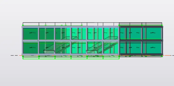
SEISMIC LOAD CALCULATION:
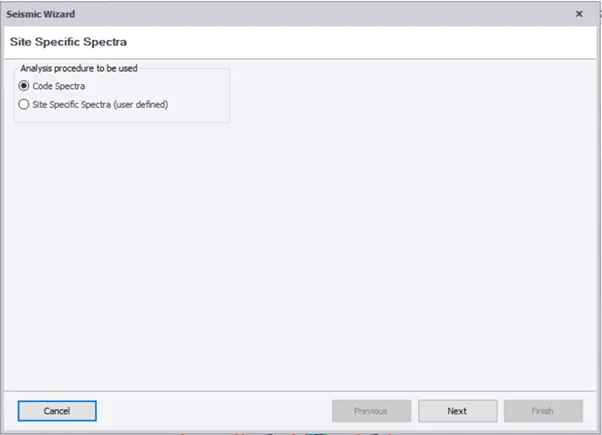
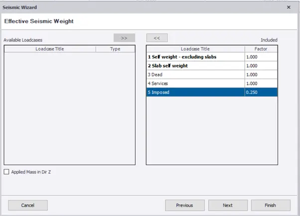
- Now under the load cases we need to select the seismic load and that will direct you to a new dialogue box.
- Now in that dialogue box you will asked to select and check all the values, check weather the values of the 1.00.
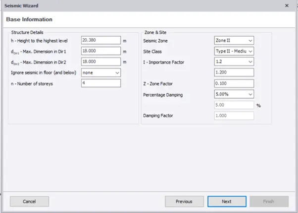
- Now you will be directed to new dialogue once you click next option.
- The dialogue boxes that appear in this process helps us to design the seismic load to the following structure.
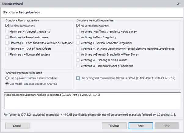
- Once all the parameter such as length, width, height and many more check is done click on Finish.
- Now if we open the down load bar we can find the seismic loads that have been applied to the structure.
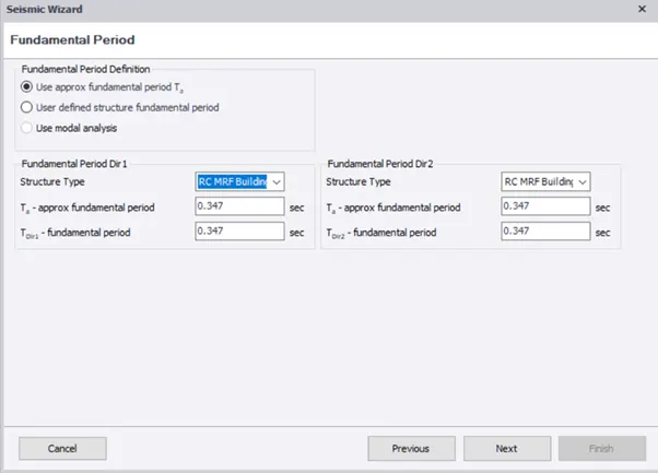
- Now that all the loads are applied we can now validate the structure to see and errors.
- If any errors found they would be listed under the validate option and when we click on the error we will be directed to that error place and it is highlighted with a solid arrow.
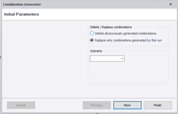
- Correct the error by changing the size of the particular beam or column.
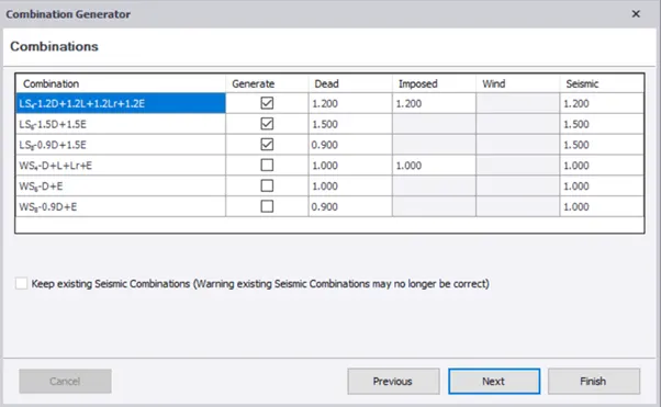
-
we will able to apply seismic load on the design members of the structure.
->Analyze and design the building as per IS standard code in TEKLA STRUCTURAL DESIGNER.
- Now select the analyse option on the top task bar, under that we have to click the 1st order liner option.
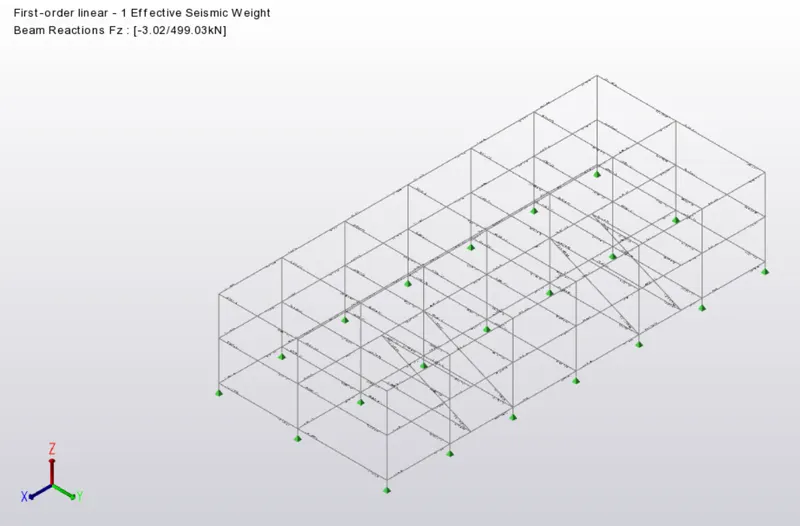
- Now the analysis is done and will show us the errors once it is done.
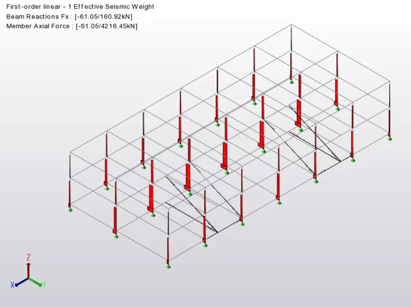
- Now click on the particular member and when we do the left click on it we get a dialogue box under that select the check member option and under that select the static option which displays another dialogue box.
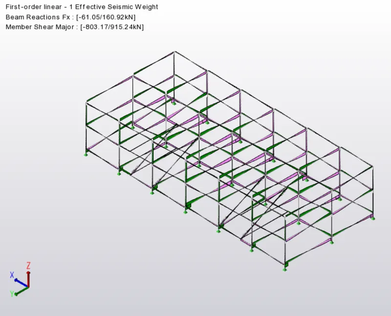
- Now in the new dialogue box we can find the load analysis manually done and there we can check the value that is obtained of the loads that we have give or the material that we have chosen.
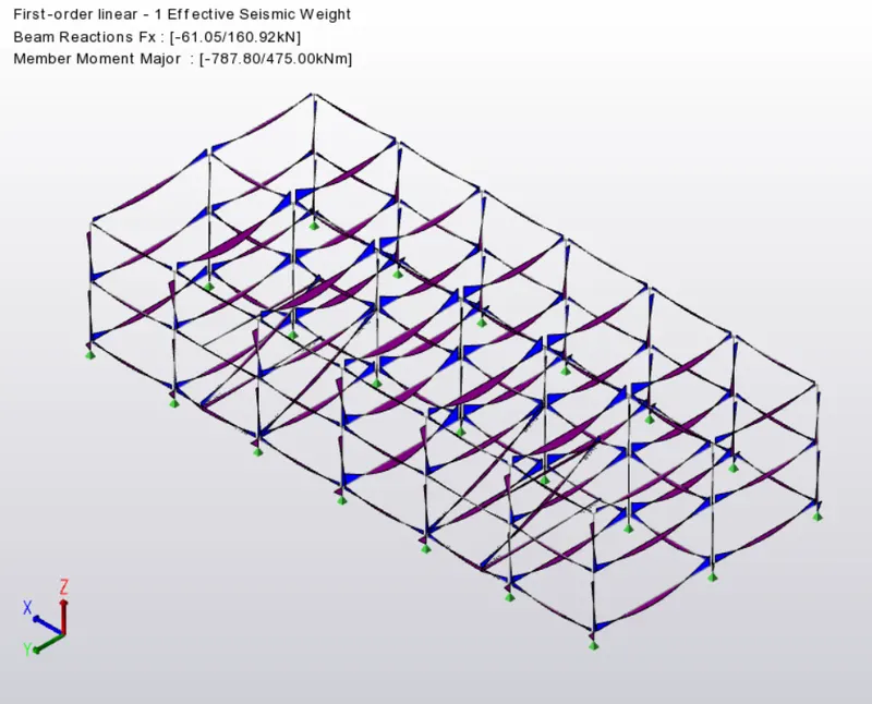
- Now check the values that we obtained by manual calculations and check the actual value that has to come out with the help of IS Code book.
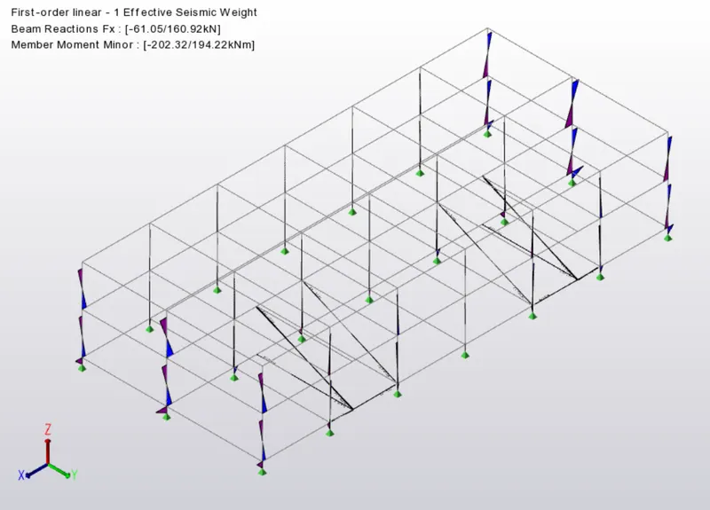
- Now change the size of the structural members accordingly.
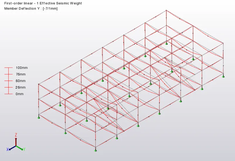
- Now validate the structure for any errors.
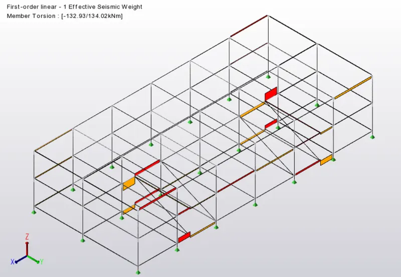
- Now that analysis is done we can move on to designing of the members of the structure.
- Now select a column and give a right click then you can notice a dialogue box.
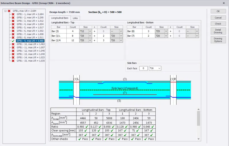
- Now in that dialogue box select the interactive design and under that select the static option.
- Now a new dialogue box appears about the properties of the column that you select.
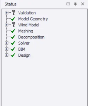
- Now check the status of the column and see weather it is red cross mark or a green tick mark.
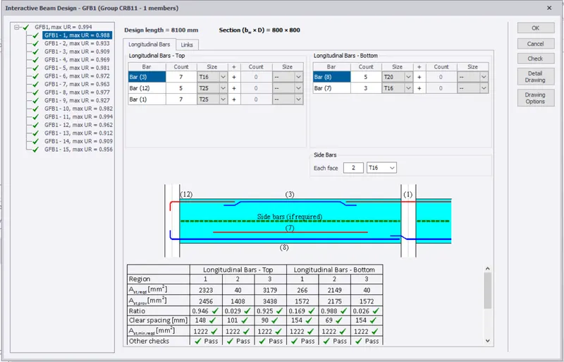
- If it is a green tick mark it says that the column requirements for the structure are satisfied.
- If it is red cross mark change the properties either by increasing or decreasing the size of the column and this would surely change the red cross mark with green tick mark.
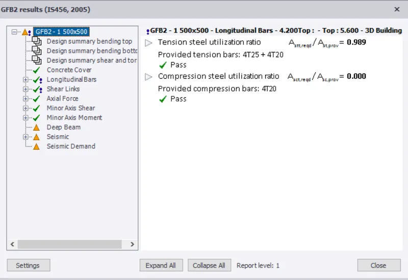
- Now select the design icon that is present on the top task bar of the of the tekla software.
- Under that select the settings option, under that select concrete and under that select the top longitudinal and bottom longitudinal values that are to be changed.
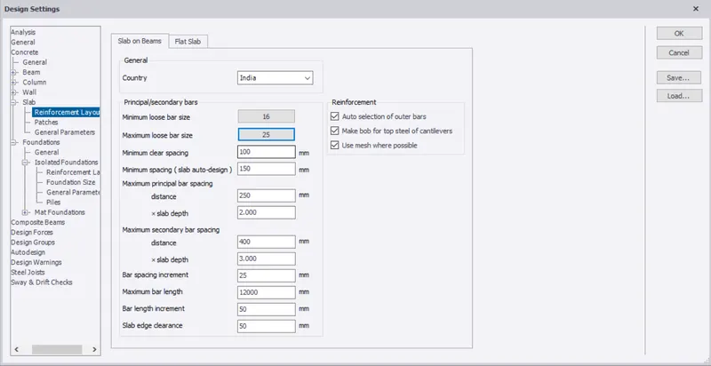
- And now change as per requirements.
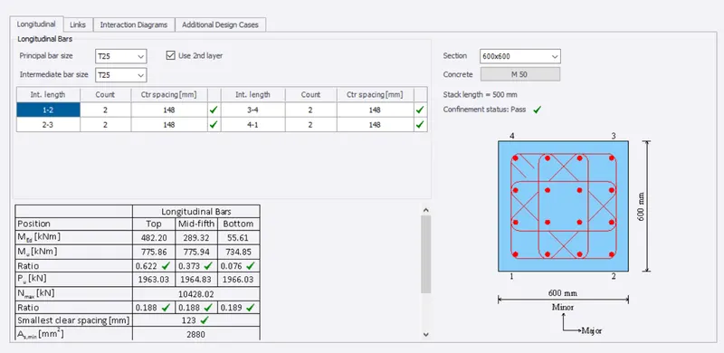
- After all that we need to open the review view.
- By doing so we will be able to check the status of the structure.
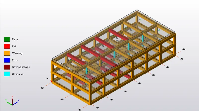
- Repeat the same process with the few RC beams and RC columns and slabs.
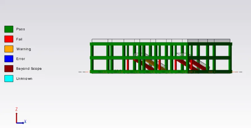
- Now for the foundations select the foundation icon.
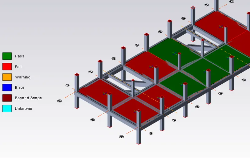
- Now you need to select the catalogue option and add desire foundation.
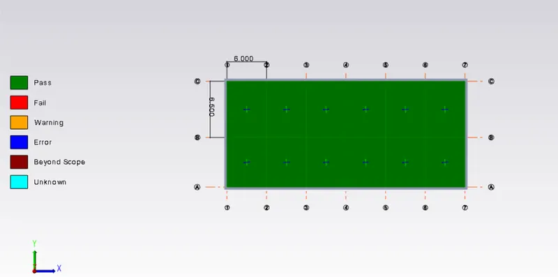
- Now you can select the pile cap column foundation option.
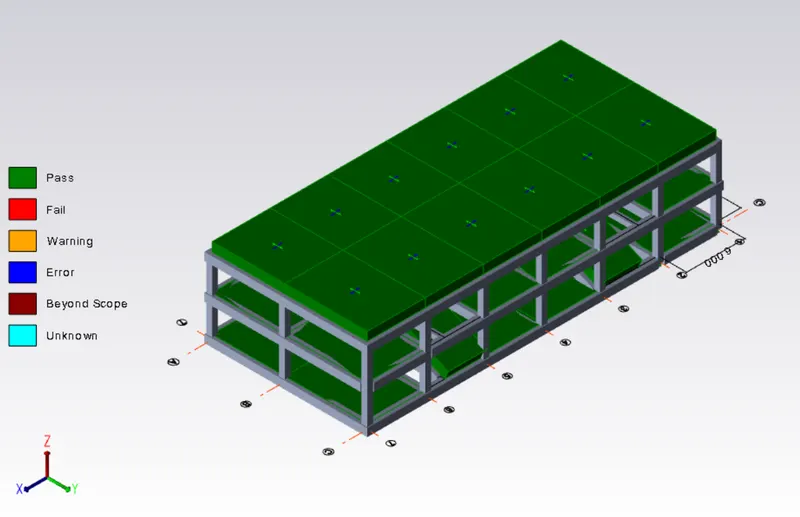
- Assign foundations for the structure.
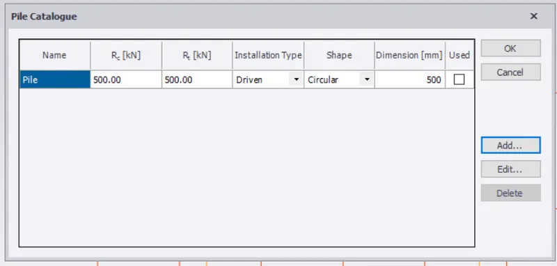
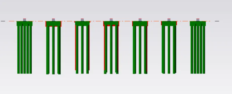
- Now design the foundation with the help of design pile cap option under the design isolated.
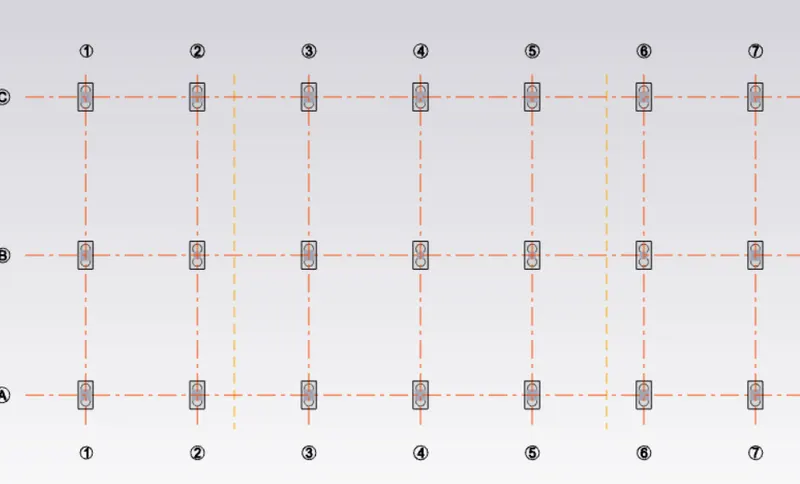
- Check for errors found.
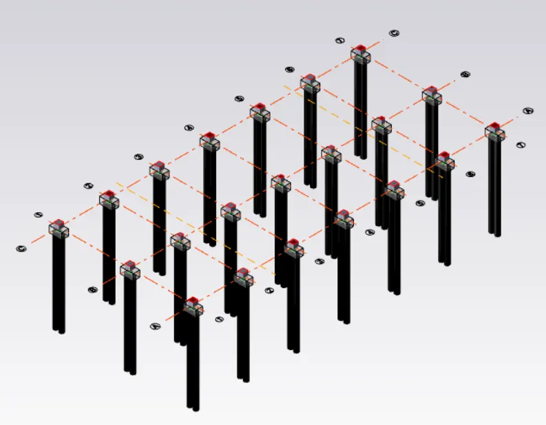
- Go to the settings option under that select the foundation option and do the required changes.
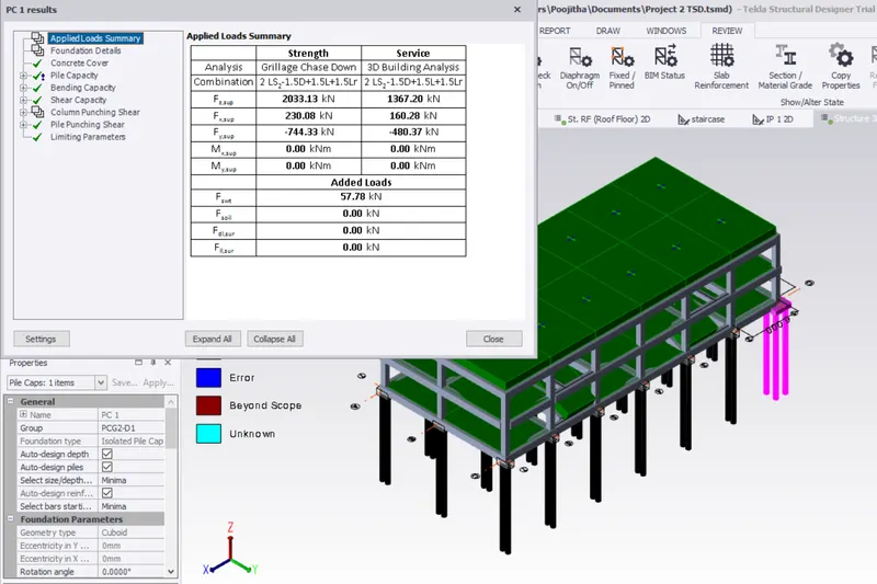
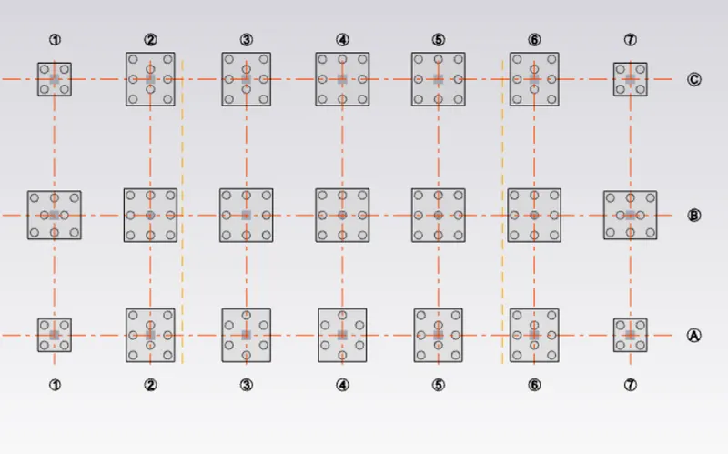
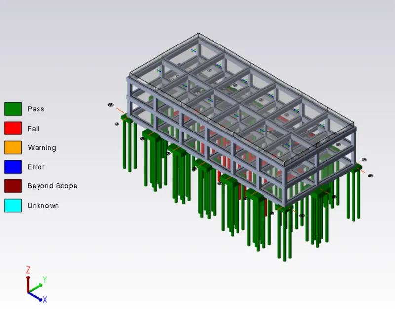
- Now you can see the structure is error free.
->REPORTS:
- Now to generate reports
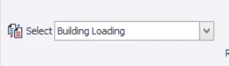
- Now under the reports tool bar we find the select option where we can choose the options.
- After selecting one among them click on the Model report.
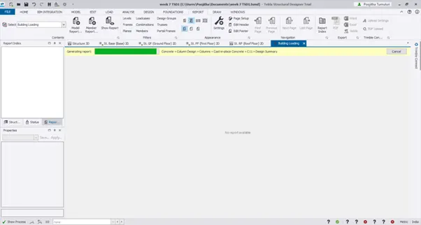
- Now you will be directed to a new dialogue box, where you have to select few among them which are required for our structure input details.
- After selecting few you can click on ok.
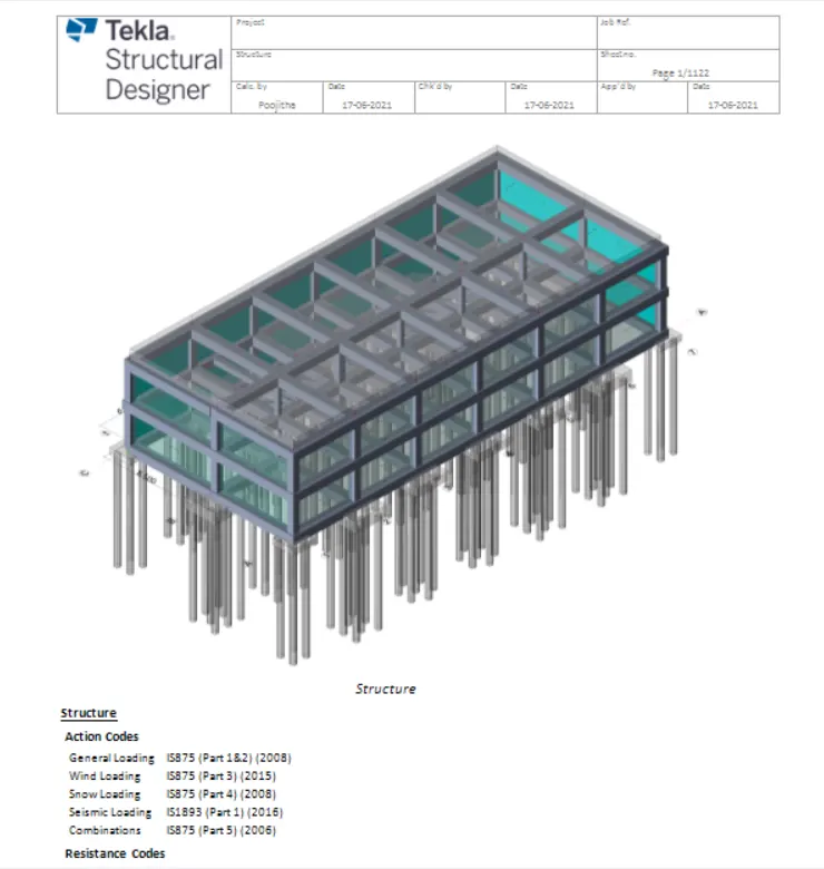
- Now select the show reports option to see them.
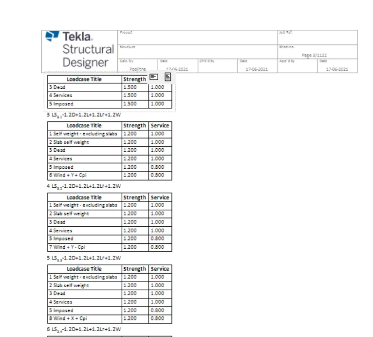
- Now you can see reports are generated on your work space.
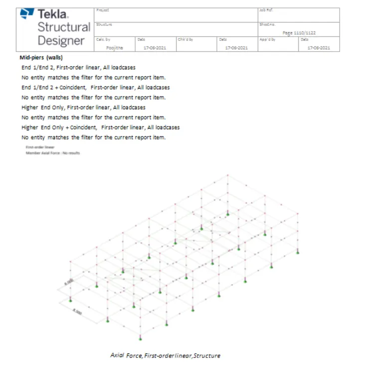
- You can click on the icon present on the tool bar for the next page and previous page options.
- Also you can click on the PDF option to generate a PDF of the reports.
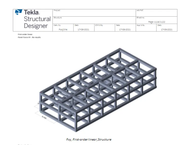
- Or you can convert the reports into any format such as PDF, Excel, Word and many more of your of your choice depending on the availability.

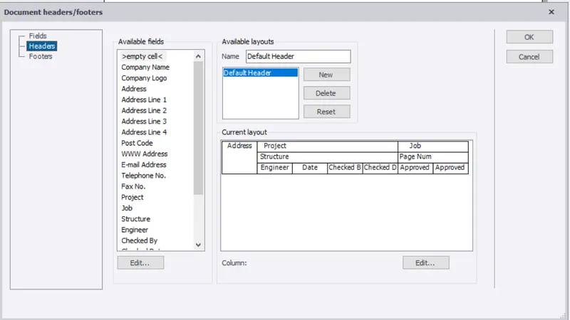
- Now with the help of edit header option you can edit the project name, address, checked by, approved by and many more.
Result:
Hence by following the above series of steps we will be able to develop general arrangement for the RC office building and analyze and design the building as per IS standard code in TEKLA STRUCTURAL DESIGNER. The building has been designed for dead, live, wind and seismic loading.
Report are generated and extract drawings for structural plans, beam reinforcement details from the software.