Project 2
Develop general arrangement for the RC office building. Analyze and design the building as per IS standard code in TEKLA STRUCTURAL DESIGNER. Refer the attached plan and elevation. The building to be designed for dead, live, wind and seismic loading.
Aim:
To develop the general arrangement for the RC office building and analyzing with design the building as per IS standard code in Tekla Structural Designer.
Procedure:
Step 1:
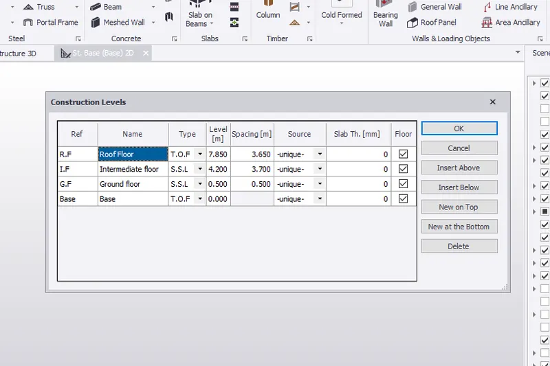
1) Go to Model tab and select Construction level
2) Edit the construction level from Base to Roof
3) Click ok
Step 2:
1) Go to Model tab
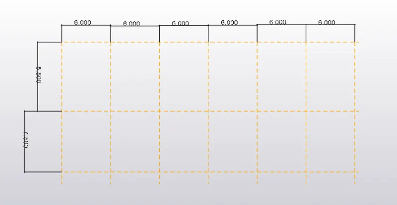
2) Select construction line under the grid option
3) Draw the grid as per the drawing provided in the question
4) Click ok
Step 3:
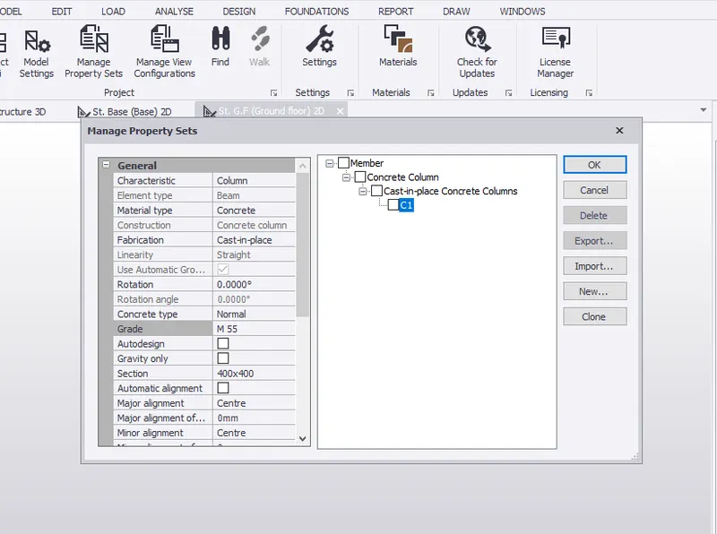
1) Go to Manage property set
2) click new and add the concrete column
3) Edit the column size as 400x400 and grade as M55
4) Clik ok
Step 4:
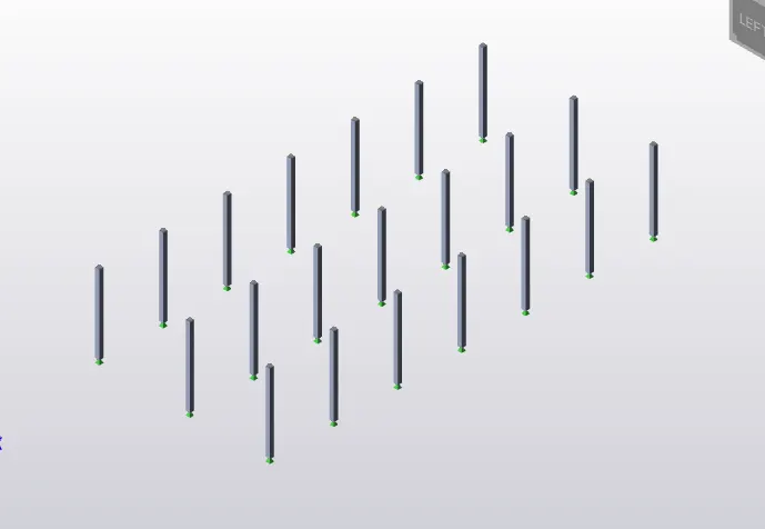
1) Go to model tab and select concrete column
2) Select C1 from property window
3) Place the column in all the grid point
4) Press ESC to exit the editing
Step 5:
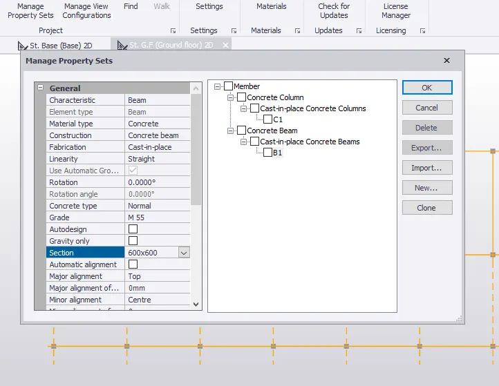
1) Go to Manage property set
2) click new and add the concrete column
3) Edit the beam size as 600 x 600 and grade as M55
4) Clik ok
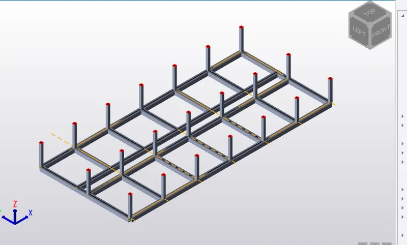
Step 6:
1) Go to model tab and select concrete beam
2) Select B1 from property window
3) Place the beam in all the grid point
4) Press ESC to exit the editing
Step 7:
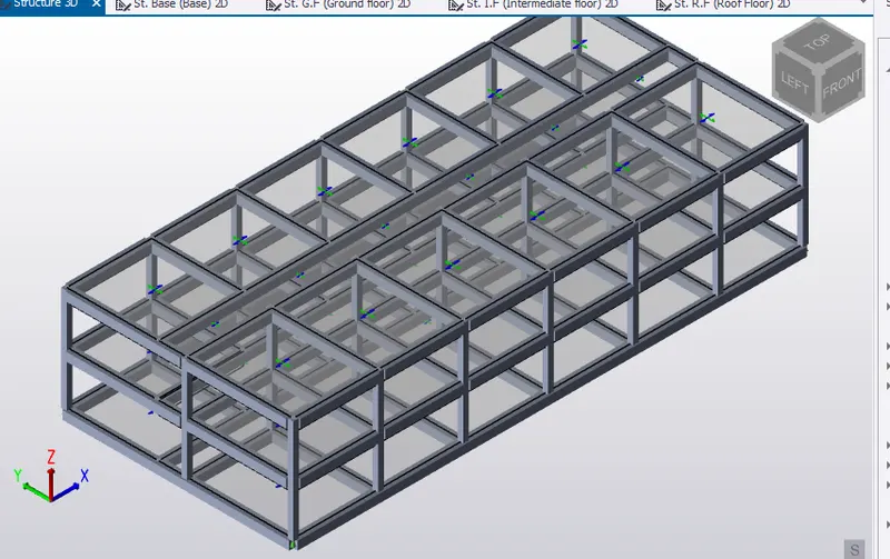
1) Follow the same procedure in first floor also
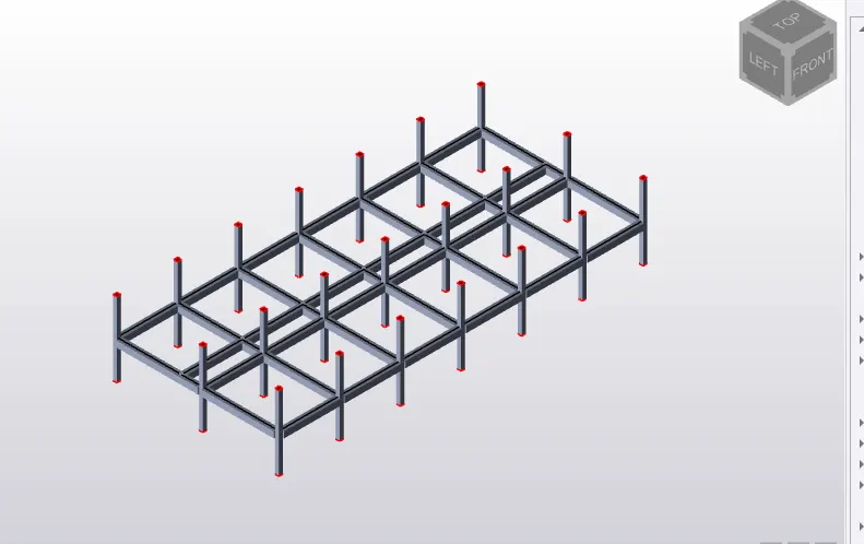
Step 8:
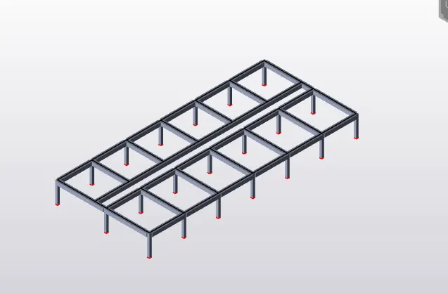
Provide the beam in roof also
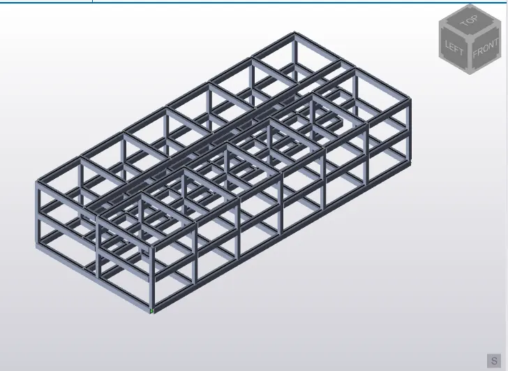
Full 3d View:
Step 9:
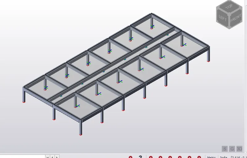
Slab Properties:
1) Go to Manage property set
2) click new and add the cast insitu slab
3) Edit the slab as M55 and overall depth as 900mm
4) Clik ok

Step 10:
1) Apply the slab properties in ground floor, first floor
Step 11:
Load Calculation:
Dead Load:
As per IS 875 Part 1
1) Slab load = (As provided by software in the model)
2) Finishing load (50mm) = 0.05m x 24 Kn/m^2 = 1.2 kN m^2
3) Brickwall loading = 150mm thickness
4) Unit weight = 20 kn/m^3
5) Floor height (G.F to F.F) = 3.7 m
6) Brickwall loading = 150 x 20 x 3.7/1000
= 11.1 Kn/m
7) Floor height (F.F to Roof) = 3.65 m
8) Brickwall loading = 150 x 20 x 3.65/1000
= 10.95 kn/m
Step 12:
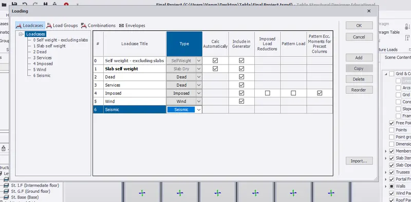
Applying Load on Model:
1) Click the Load tab in the ribbon panel
2) Select Load cases and add the new loads such as Wind, Crane, and Seismic
3) Choose the type of the load as per load case titles.
4) Click ok
Step 13:
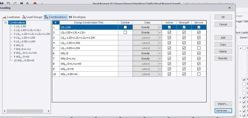
Generating Load Combination:
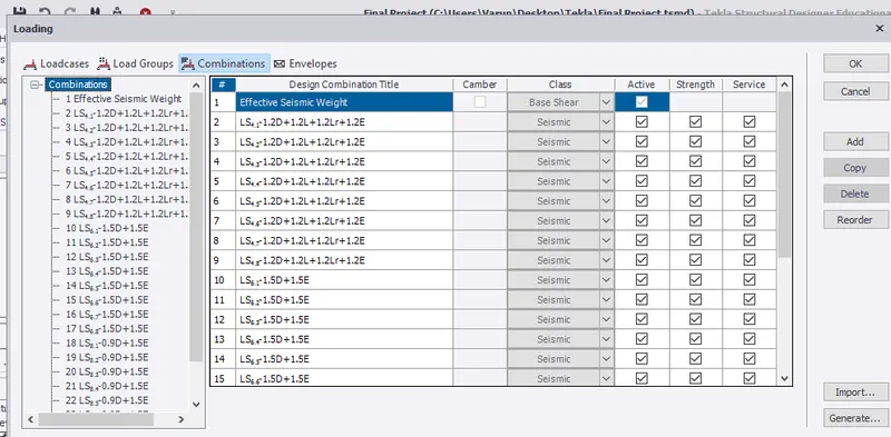
1) To generate the load combination from our entered load cases, first need to select the load combination from the Load tab in the ribbon panel
2) Click Generate and procee the load combinations
3) Then click finish once we got all the load combinations.
4) Click Ok
Step 14:
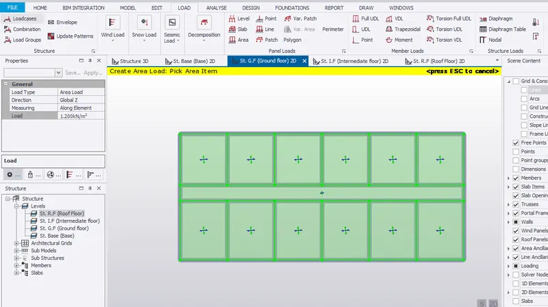
Applying Dead loads on Ground floor:
1) Click the drop down list from the bottom tool bar
2) Choose Dead load from the list
3) Select the Area loading option from the ribbon tab
4) Change the load value under the property panel to 1.2 kn/m
Step 15:
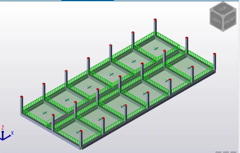
Similarly apply the brickwall load in ground floor
Step 16:
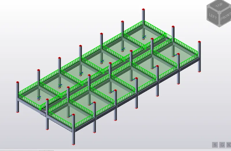
1) Apply the brickwall load in first floor also
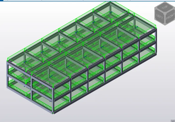
Full Structure:
Step 17:
Live load Calculation:
As per IS 875 part 2, table 1:
Toilet = 2 kN
Staircase = 5 kN
Store room = 5 kN
Equipment room = 10 kN
Conference room = 5 kN
Canteen = 3 kN
Office room = 3 kN
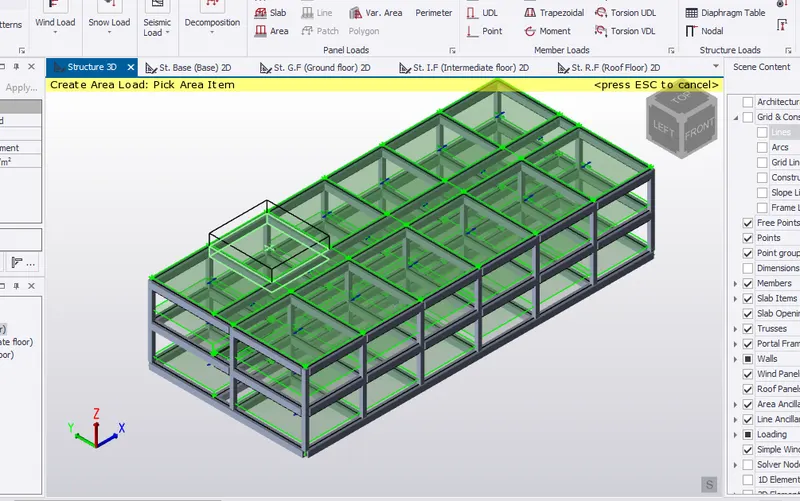
1) Apply live load ground and first floor.
2) Live loads taken from IS 875 part 2, Table 1
3) Change the load type as Imposed and select area load
4) Then place the loadng at suitable rooms
Step 18:
Seismic Load:
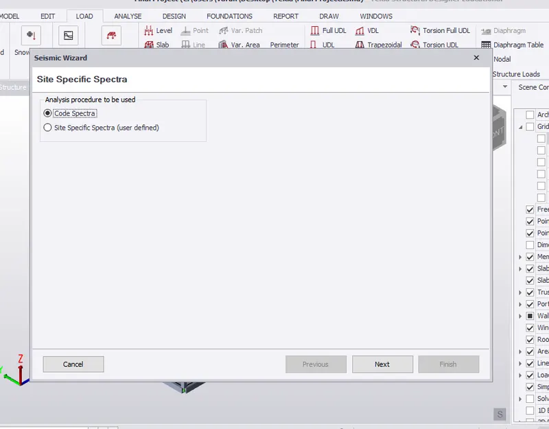
1) Go to Load tab and select seismic load option
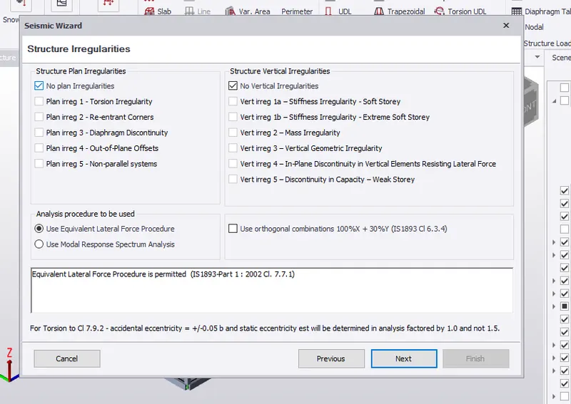
2) click next
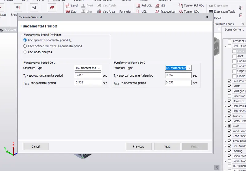
Choose RC moment resisting frame option from structure type
Therefore the load combinations are generated
Step 19:
Analysis:
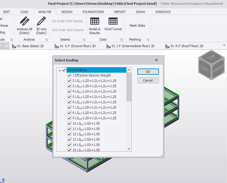
1) Go to Analyze tab
2) Select 1st order analysis and choose the load combination
3) Click ok
Step 20:
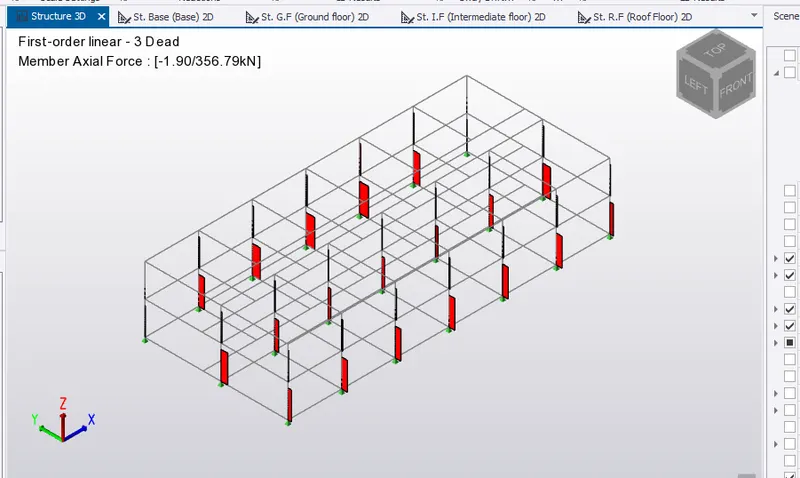
1) Click result view and choose the axial force
2) Select the load type as dead load
3) Azial force of Fz obtained
Step 21:
1) Check the slab using Review tab
2) Click status
3) Check all the slabs whether it is passing or failing
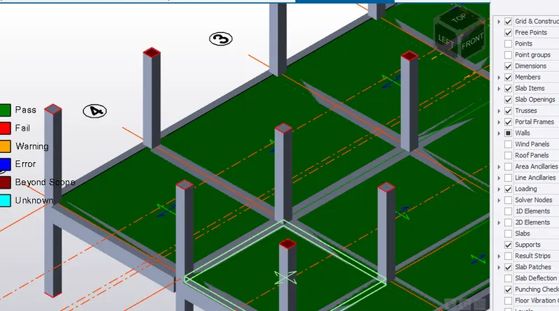
Similarly do this procedure for all the floors
Step 22:
Foundation:
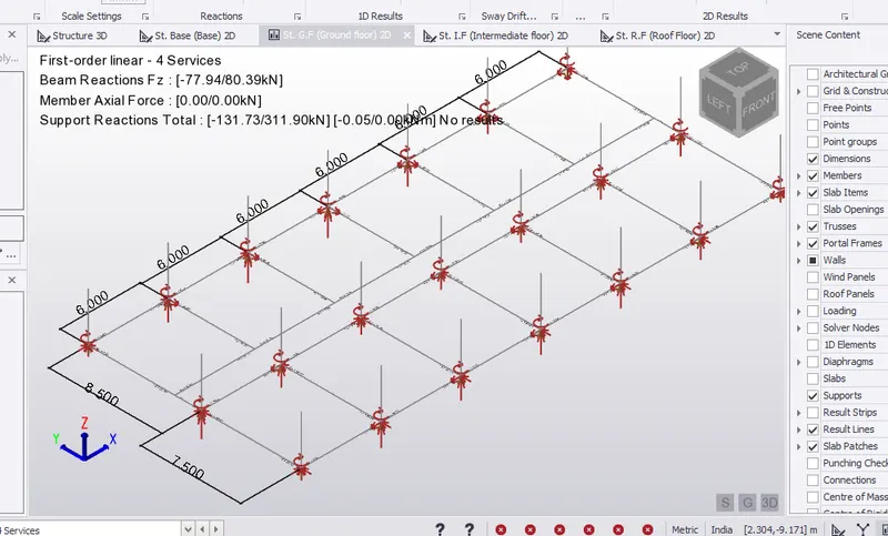
1) Open Ground floor plan
2) Go to Result view and select the reactions
3) switch it to the view of base reactions of Fz value
Step 23:
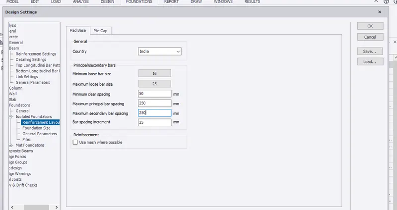
1) Go to Foundation tab and select setting
2) Enlarge the isolated foundation option and edit the reinforement details
3) Click Pile cap and choose minimum no of bar from 12 to 16
4) Change the spacing also
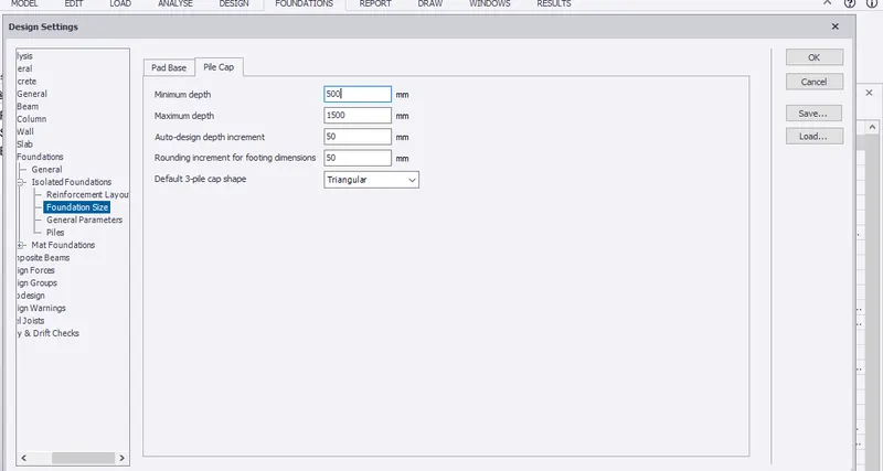
Step 24:
1) Go to foundation size option and edit the foundation depth also
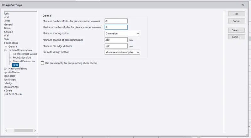
Step 25:
1) Go to Pile and edit the pile spacing
Step 26:
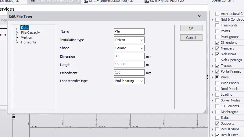
1) To edit the pile type go to foundation
2) click Catalogue
3) Press edit option and edit the pile types
Step 27:
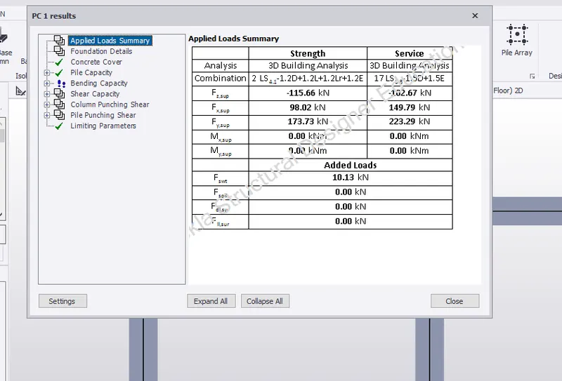
1) Go to foundation and select pad column base
2) Draw the pile and check member
Step 28:
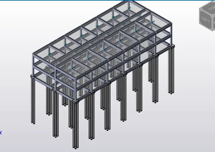
1) Place the piles in all the column area
Step 29:
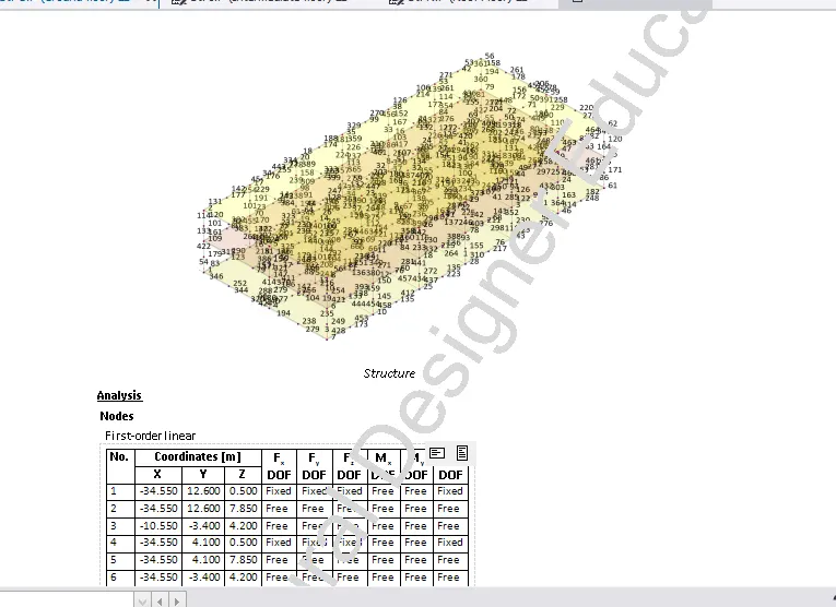
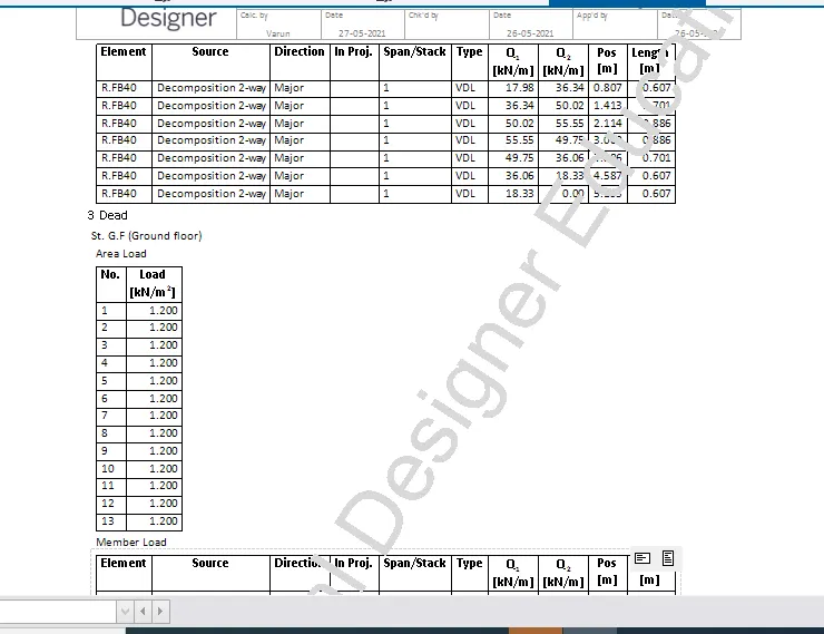
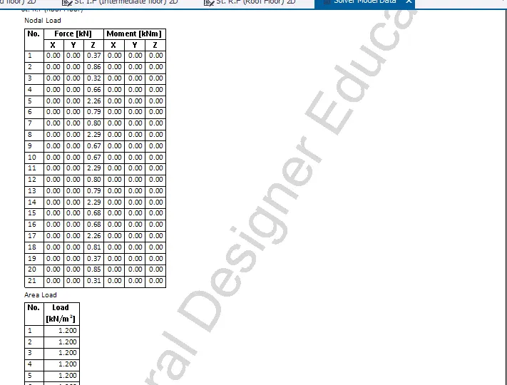
Report:
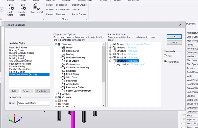
1) Go to report tab
2) Select the levels, load, loadcase and combination
3) Click ok
Step 30:
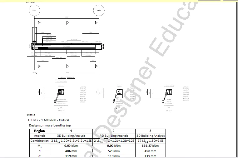
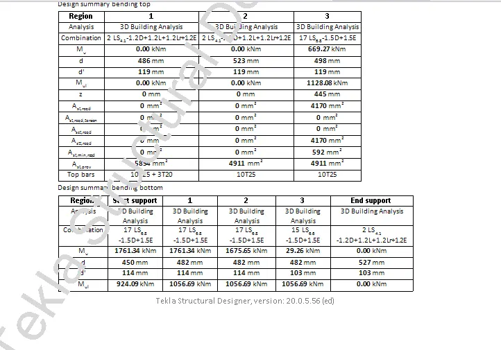
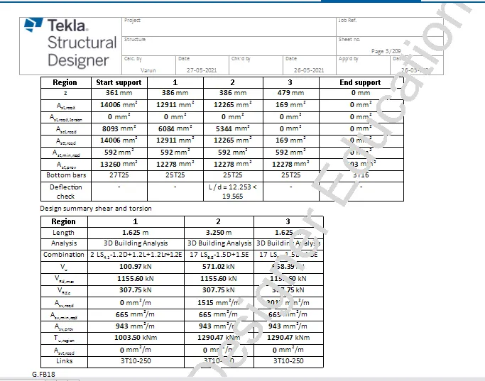
Generate the report forBeam and column design also