Project 2- Geometry clean up and meshing of the rear suspension assembly according to the given quality criteria in ANSA
Objective:- To mesh suspension assembly according to the given quality criteria and provide the appropriate connection wherever required.
|
|||||
| S.No. | Quality Criteria | Value | |||
| 1 | Target/Average Length | 6.5 | 4 | ||
| 2 | Minimum Length | 5 | 2 | ||
| 3 | Maximum Length | 10 | 6 | ||
| 4 | Skewness | 45 | 45 | ||
| 5 | Tet Collapse | 0.2 | 0.2 | ||
| For Entities Thickness Less Than 5mm | ||
| S.No. | Quality Criteria |
Value |
|
1 |
Target/Average length |
4 |
|
2 |
Minimum Length |
2 |
|
3 |
Maximum Length |
6 |
|
4 |
Aspect |
3 |
|
5 |
Warpage |
15 |
|
6 |
Skewness |
45 |
|
7 |
Jacobian |
0.7 |
|
8 |
Minimum Quad Angle |
45 |
|
9 |
Maximum Quad Angle |
135 |
|
10 |
Minimum Tria Angle |
30 |
|
11 |
Maximum Tria Angle |
120 |
Procedure:-
- Open ANSA and open the component file which is in ".ansa" as provided.
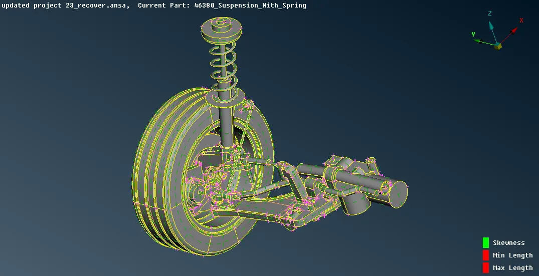
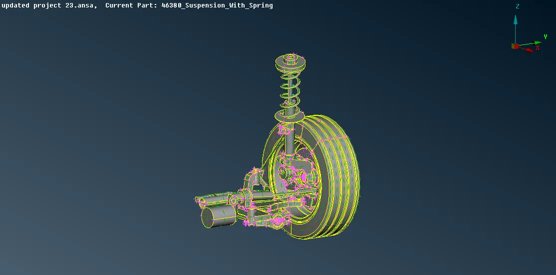
- Isolate all the entities into different property cards and name them, few are mentioned below.
|
1. Tyre |
2. Rim |
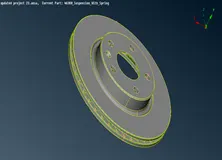
3. Disc Brake Rotor |
|
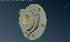
4. Wheel Hub |
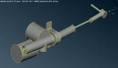
5. Tie Rod |
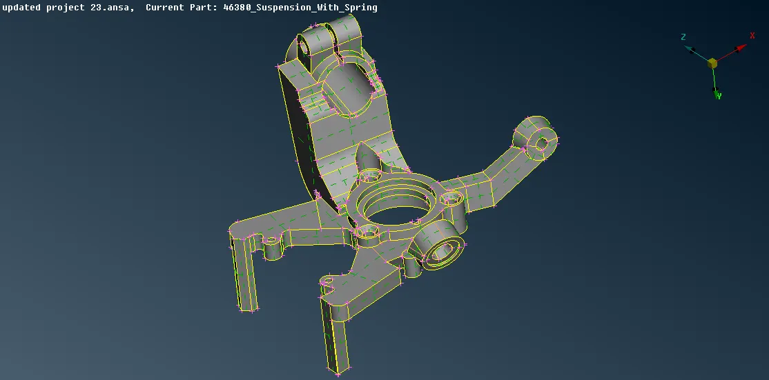
6. Steering Knuckle |
|
|
8. Wishbone |
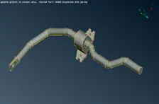
9. Sway Bar |
|
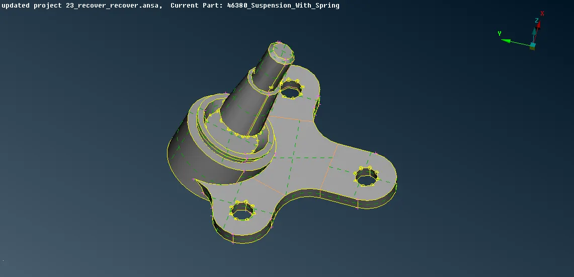
10. Ball joint |
11. Bush |
12. Coil Spring |
|
13. Upper Strut Mounting |
14. Strut Shaft |
15. Lower Spring Seat |
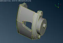 7. Brake Calliper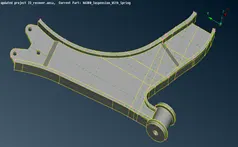
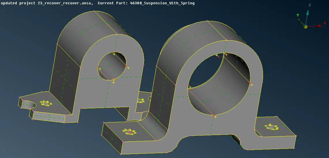
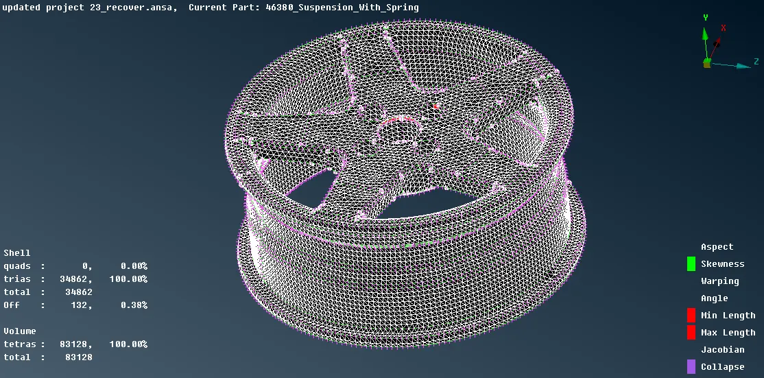
- After isolating into different property card the entities can mesh for volume mesh, so in order to generate volume mesh it can be done either by batch meshing process or by manually where shell tria mesh has to be generated which then can be converted to volume mesh and as per quality criteria the rim and tyre have different criteria than rest of the entities also there are entities which are below 5mm thickness which can be meshed by extracting midsurface and then applying mixed mesh.
- For Tyre And Rim
- Turn visible only for tyre and rim from the property window and click on the lock present under focus.
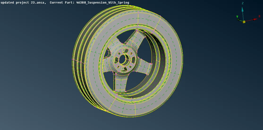
- Use !Not option under focus to view each entity separately, under Tools select geometry and check for any geometry error if present click on the fix or use the options present under Modules -> Topo to fix the errors, also suppress the non required cons for the better mesh.
- Before meshing can be done set the quality and mesh parameters by using "Quality Criteria" and "Mesh parameter" form the "Utilities". Also, set the length for the entities by Modules -> Mesh -> Perimeter -> Length -> for both Perimeter and Macro select the visible entities and provide the values.
- To mesh the entity Module -> Mesh -> Mesh Generation -> Spot Mesh -> Option List (Tria/Ortho Tria) -> Select the surface of the entities to mesh.
- For the curve regions apply Ortho tria and for the plane region apply tria.
- For the elements failing for the quality criteria can be remesh by reconstruct option and also smooth option can be applied which is present under Modules -> Mesh -> Shell Mesh, while remeshing check in the options list for the element type.
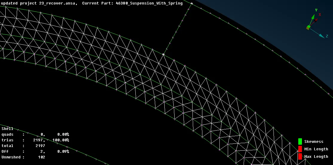
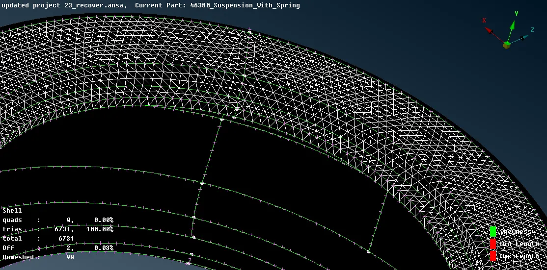
(Tyre Curve Part Meshed With Ortho Tria) (Tyre Plane Part Meshed With Tria)
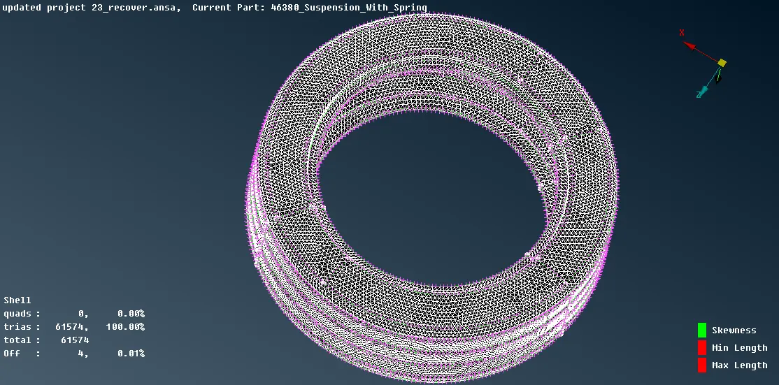
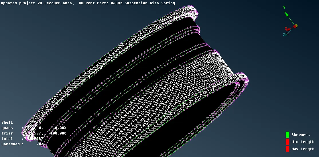
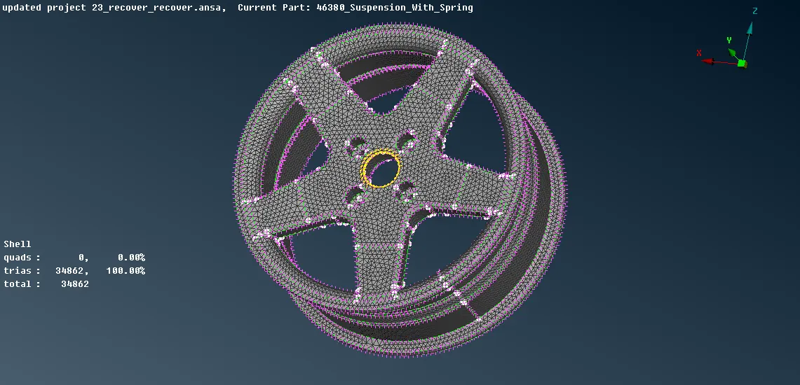
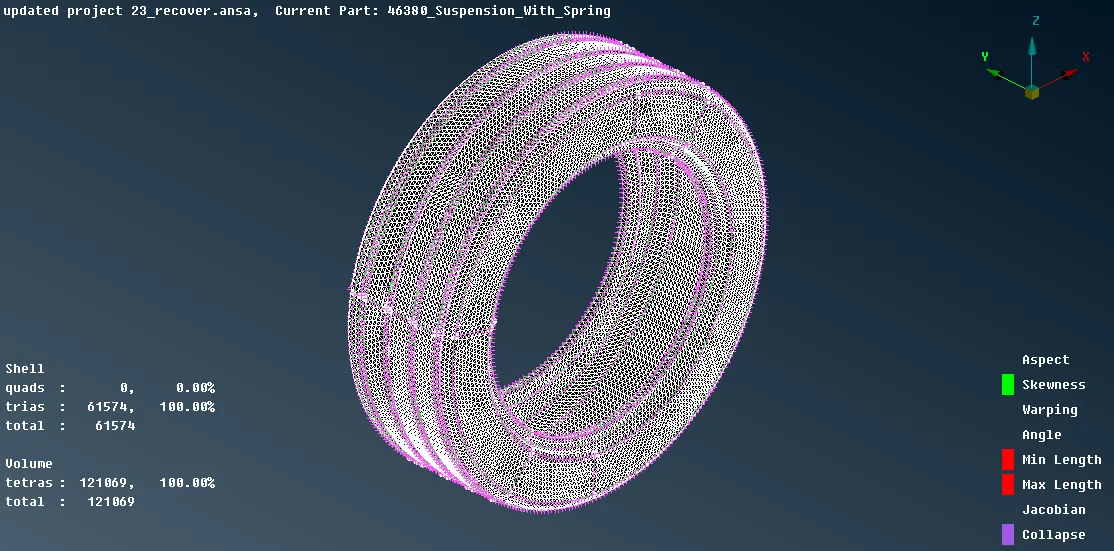
- After shell tria mesh the volume tetra mesh can be done but before that each entity should be defined as the volume which can be done by Module -> Volume mesh -> Volume -> Define -> Manual -> Auto -> select entities -> middle mouse click -> in the panel right-click to "NEW" and select PSOLID. If the volume of different entities are stored under one PID than entities can be transferred to different PIDs by Modules -> Volume Mesh -> Volumes -> Set PID.
- Now to mesh the entity Module -> Volume mesh -> Unstructured mesh -> Tetra FEM and select the entity to mesh.
- Check the meshed entity only for tetcollapse.
- If there is any element failing for tetcollapse than fix it by using Module -> Volume mesh -> Improve -> Fix quality or using the Module -> Mesh -> Grids -> Move -> and change the height of the element by dragging it.
- Finally, check for kinks and dip of the tetra mesh elements which can be solved using the Module -> Mesh -> Grids -> Move -> and change the height of the element by dragging it.
- For Entities Whose Thickness Is Above 5mm
- The entities whose thickness is above 5mm need to be volume meshed, so check the entities thickness by Utilities -> Measure.
- Use the visible from the entities stored in the property to check one by one and at the same time check for geometric error by Tools -> Check -> Geometry, if any error found click on the fix or use the option present under Modules -> Topo to clear the error, also suppress the non required cons for the better mesh.
- Before meshing can be done set the quality and mesh parameters by using "Quality Criteria" and "Mesh parameter" form the "Utilities". Also, set the length for the entities by Modules -> Mesh -> Perimeter -> Length -> for both Perimeter and Macro select the visible entities and provide the values.
- To mesh the entity Module -> Mesh -> Mesh Generation -> Spot Mesh -> Option List (Tria/Ortho Tria) -> Select the surface of the entities to mesh.
- For the curve regions apply Ortho tria and for the plane region apply tria.
- For the elements failing for the quality criteria can be remesh by reconstruct option and also smooth option can be applied which is present under Modules -> Mesh -> Shell Mesh, while remeshing check in the options list for the element type.
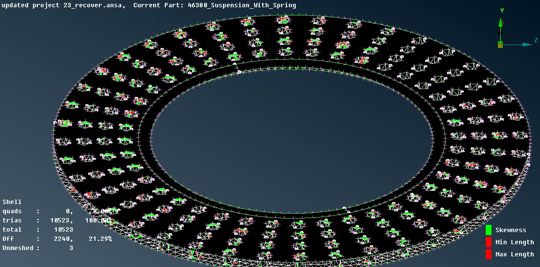
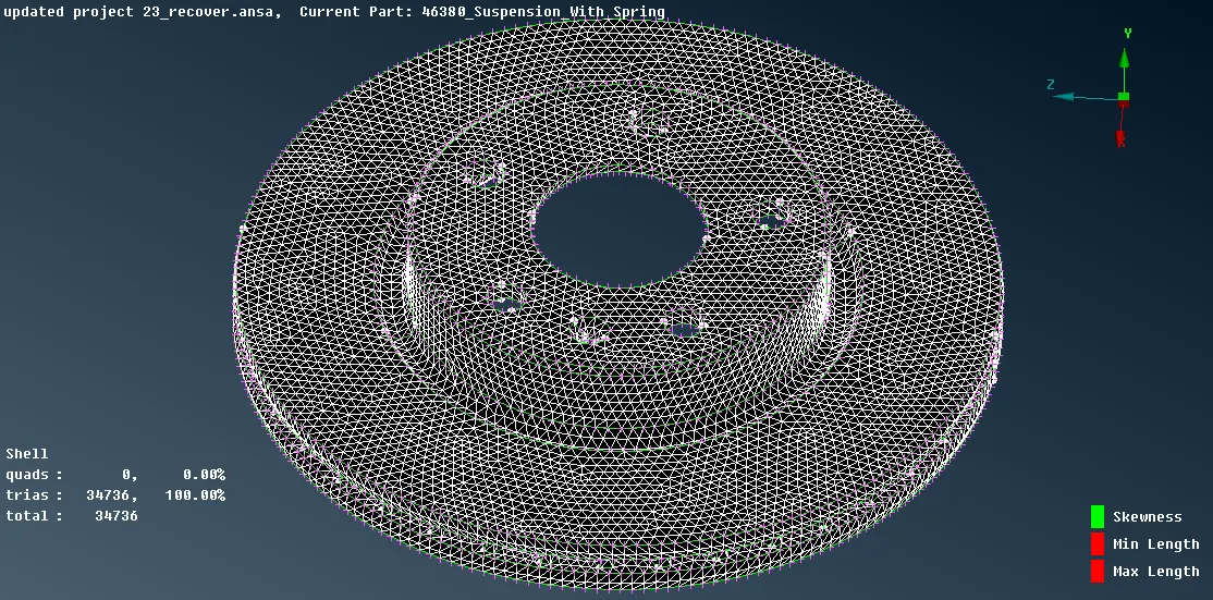
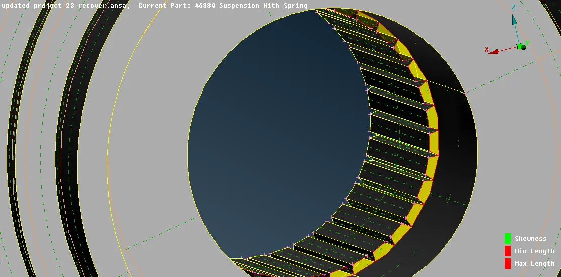
- The wheel hub has teeth which are not for meshing so it can be deleted by Modules -> Topo -> Faces -> Delete, and the new surface can be generated for the circular region by Moules -> Topo -> Faces -> New -> Coons -> Select the free edge to generate the surface. After that, it can mesh can be generated by above steps.
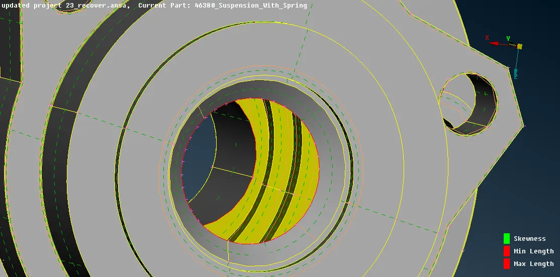
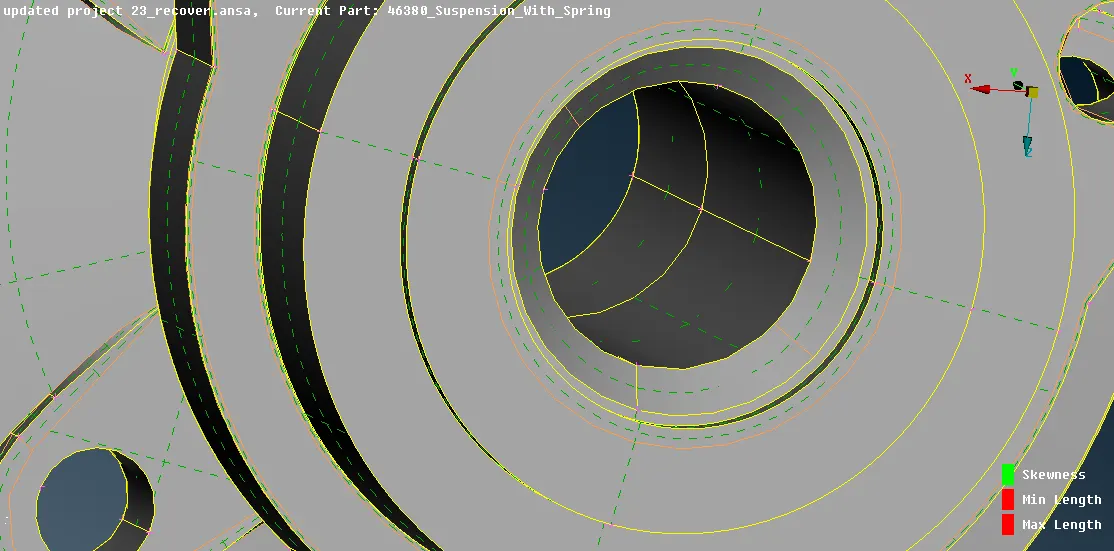
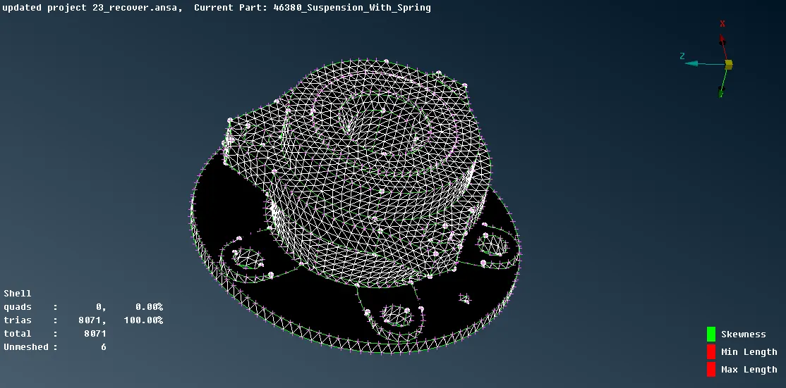
- First mesh the holes and curve region with ortho tria then mesh the plane surface with tria.
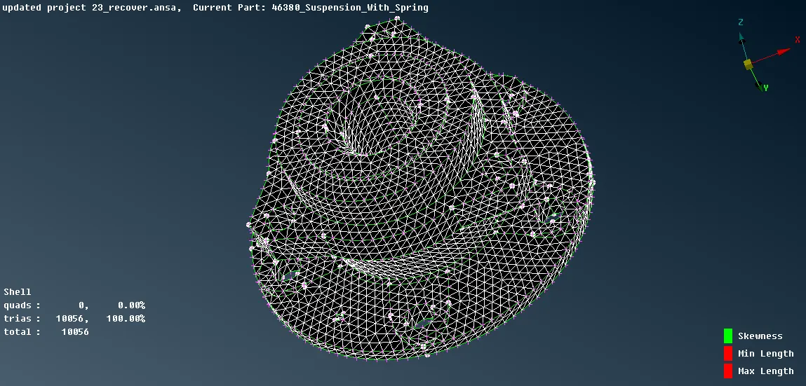
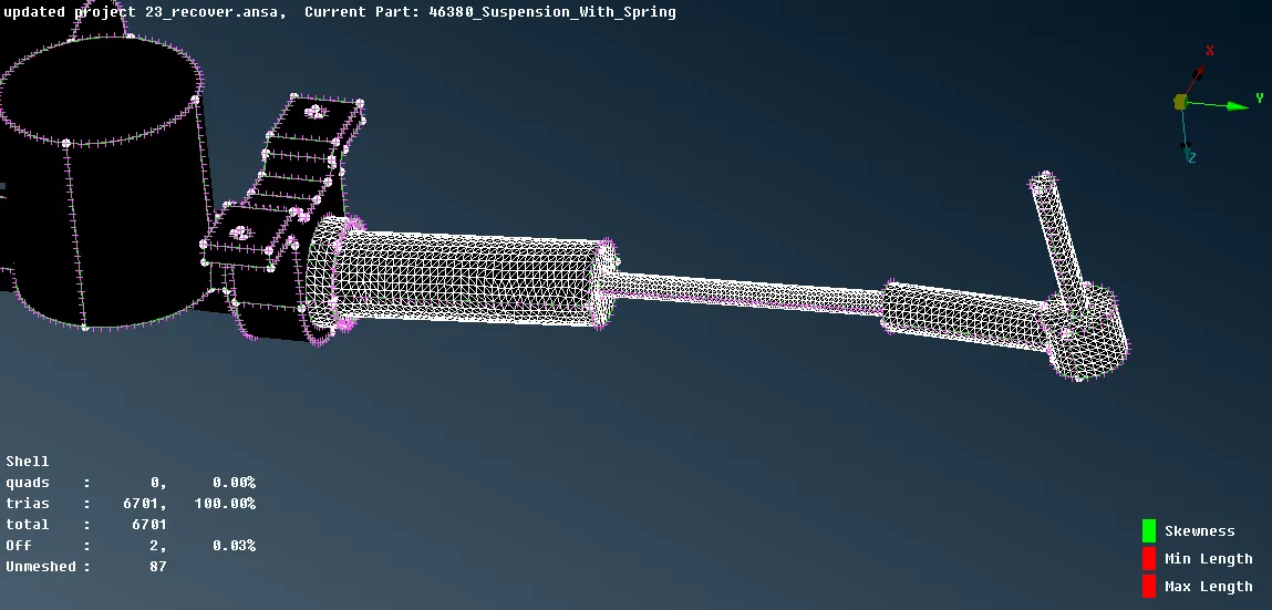
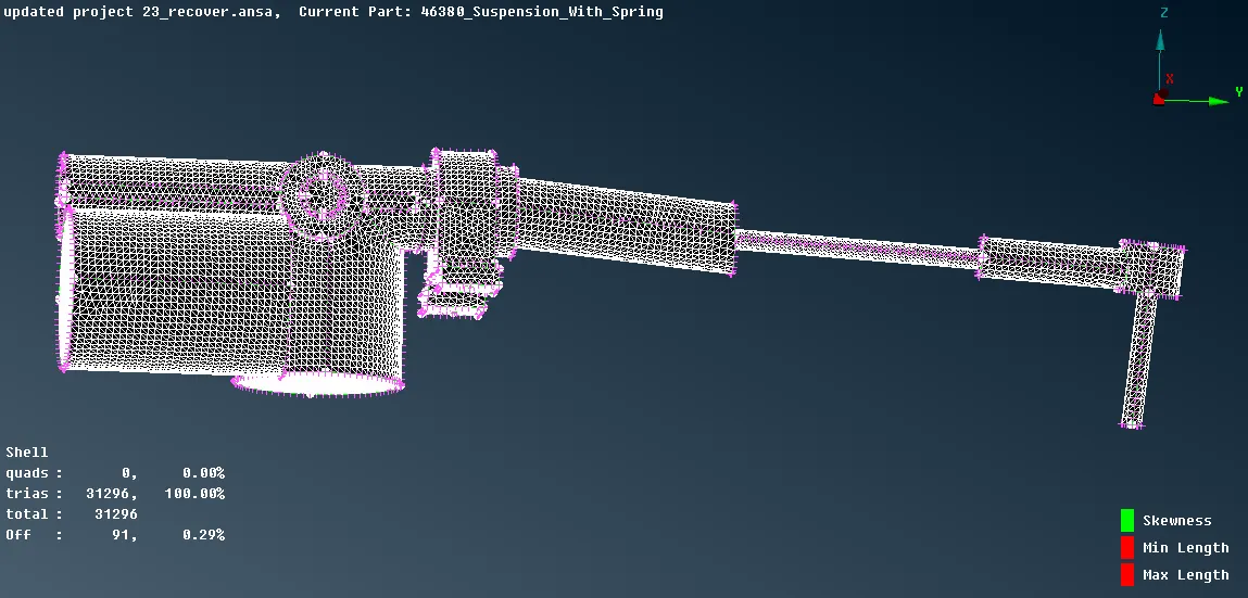
(Meshing of Tie Rod)
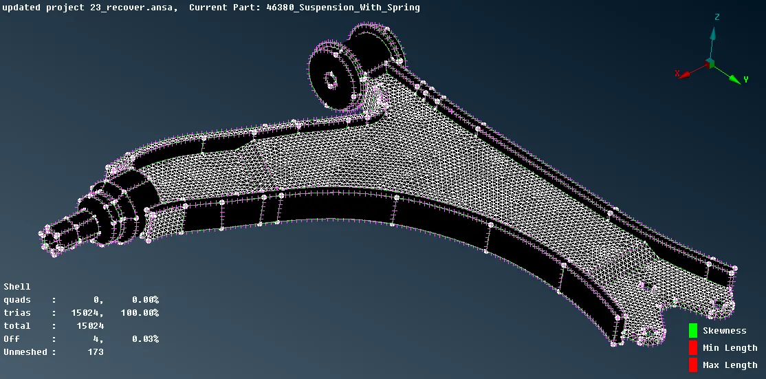
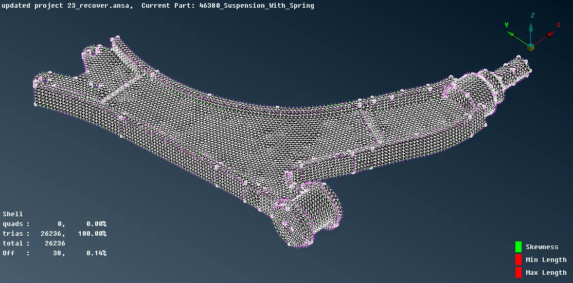
(Meshing of Wishbone)
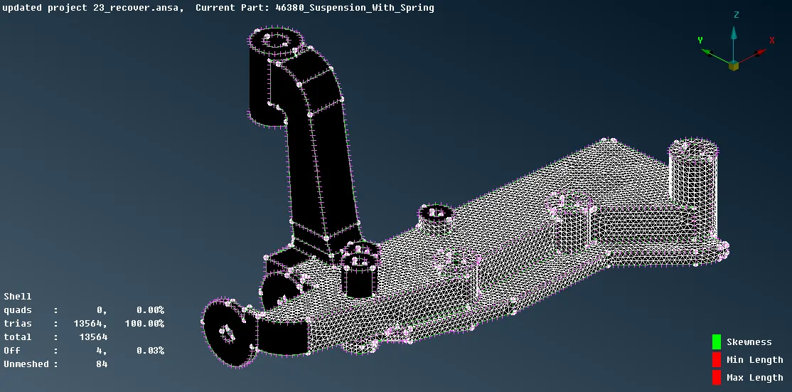
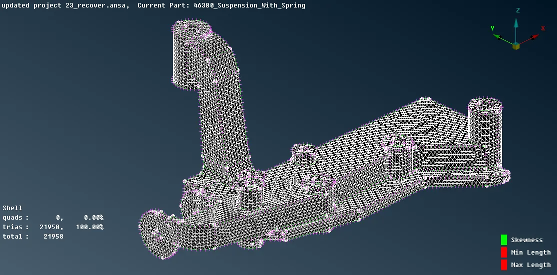
( Meshing of Frame)
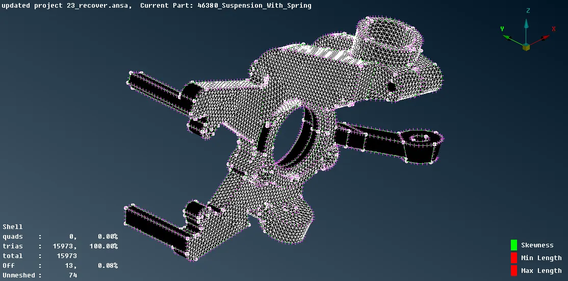
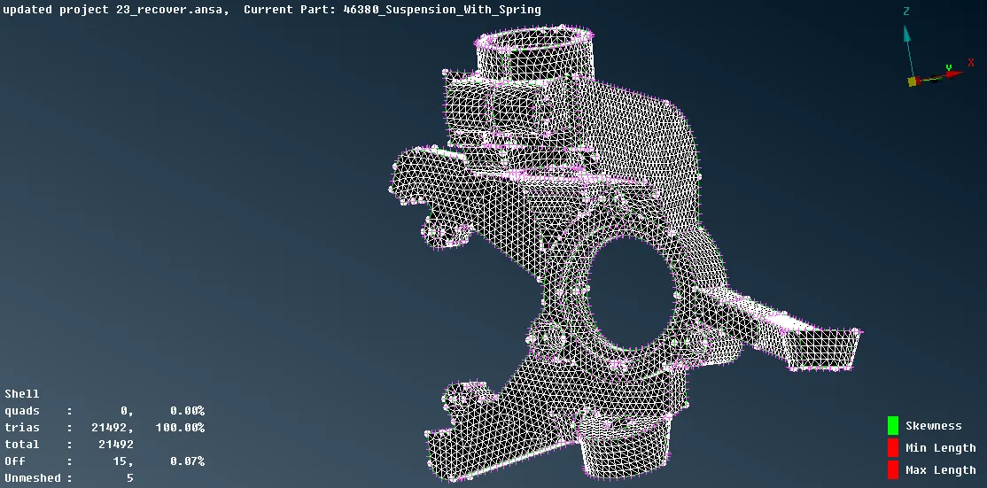
( Meshing of Steering Knuckle)
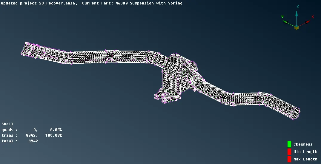
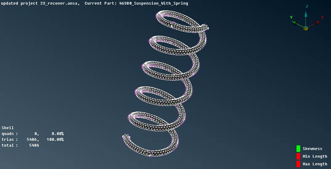
( Meshing of Sway Bar) ( Meshing of Coil Spring)
- After generating shell tria mesh of all the entities the volume tetra mesh can be done but before that each entity should be defined as the volume which can be done by Module -> Volume mesh -> Volume -> Define -> Manual -> Auto -> select entities -> middle mouse click -> in the panel right-click to "NEW" and select PSOLID. If the volume of different entities are stored under one PID than entities can be transferred to different PIDs by Modules -> Volume Mesh -> Volumes -> Set PID.
- Now to mesh the entity Module -> Volume mesh -> Unstructured mesh -> Tetra FEM and select the entity to mesh.
- Check the meshed entity only for tetcollapse.
- If there is any element failing for tetcollapse than fix it by using Module -> Volume mesh -> Improve -> Fix quality or using the Module -> Mesh -> Grids -> Move -> and change the height of the element by dragging it.
- Finally, check for kinks and dip of the tetra mesh elements which can be solved using the Module -> Mesh -> Grids -> Move -> and change the height of the element by dragging it.
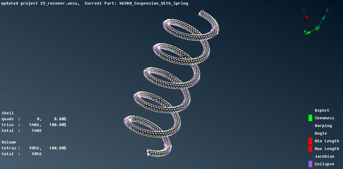
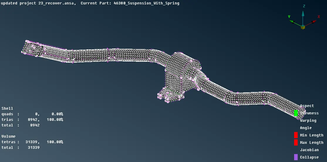
(Volume Meshing of Coil Spring) (Volume Meshing of Sway Bar)
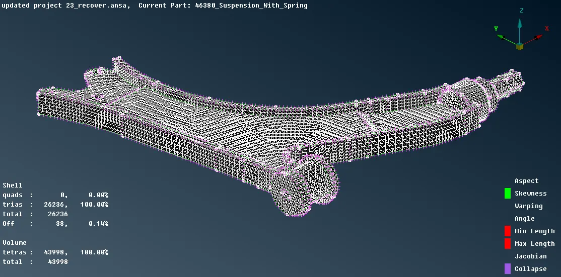
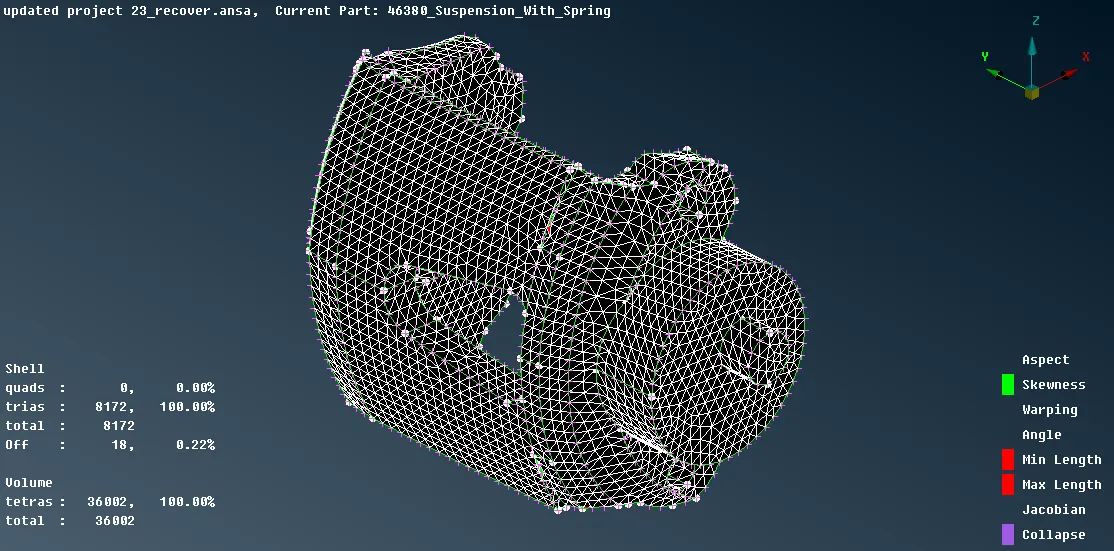
(Volume Meshing of Wishbone) (Volume Meshing of Brake Calliper)
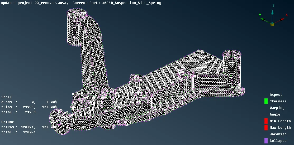
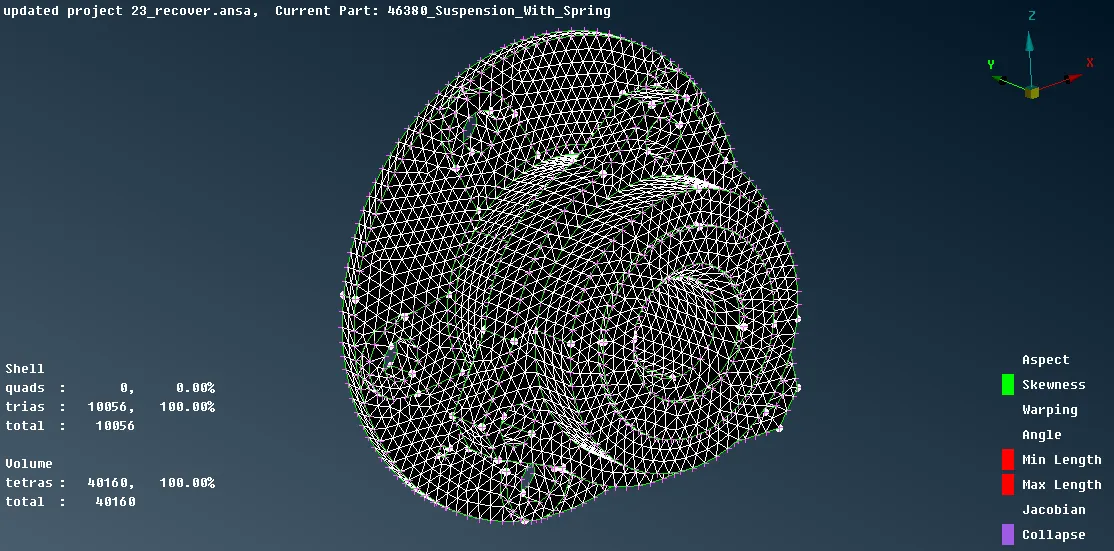
(Volume Meshing of Frame) (Volume Meshing of Wheel Hub)
- Similarly volume mesh can be generated for all the entities which are above 5mm thickness.
- For Entities Below 5mm Thickness
- For entities below 5mm thickness mesh with mixed elements, but before meshing midsurface of the entities need to extracted which can be done by either automatically by Midsurface option for uniform feature and thickness component or by manual midsurface by offset the surface by Offset option, both of which are present under Modules -> Topo -> Faces.
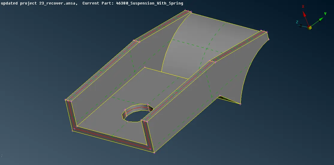
- There are only 2 entities which midsurface can be extracted one is the bracket and the other is lower spring seat.
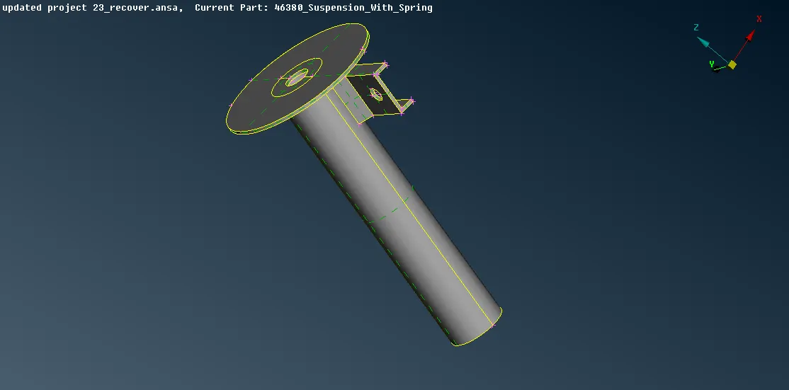
- Midsurface for bracket will be extracted by Modules -> Topo -> Faces -> MidSurf -> Skin.
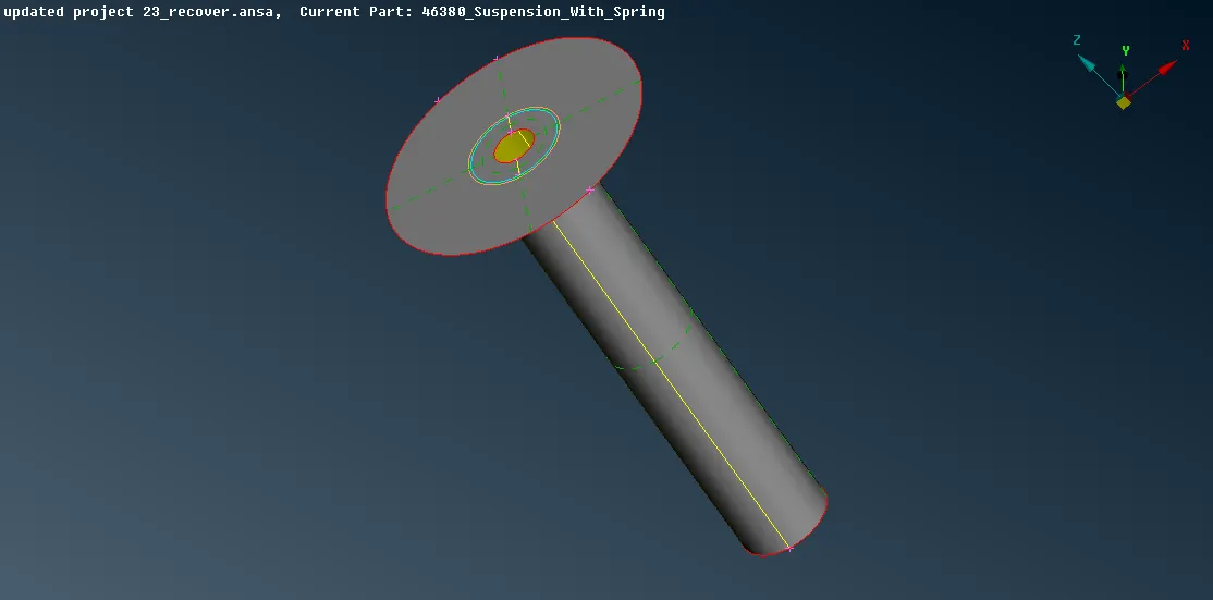
- Midsurface of the Lower spring seat can be extracted by offset option, but first, measure the thickness of the entity as the offset value will be half of the thickness.
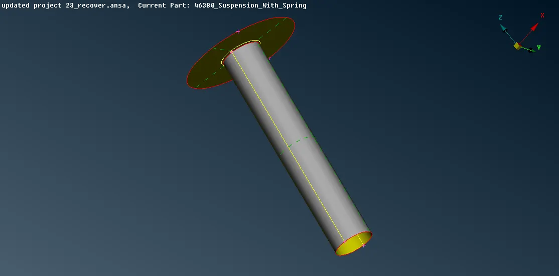
- Extend the lower portion to connect the upper part after the offset and set a new PID for the offset part and provide the measured thickness.
- Before meshing can be done set the quality and mesh parameters by using "Quality Criteria" and "Mesh parameter" form the "Utilities". Also, set the length for the entities by Modules -> Mesh -> Perimeter -> Length -> for both Perimeter and Macro select the visible entities and provide the values.
- To mesh the entity Module -> Mesh -> Mesh Generation -> Spot Mesh -> Option List (Mixed) -> Select the surface of the entities to mesh.
- For the elements failing for the quality criteria can be remesh by reconstruct option and also smooth option can be applied which is present under Modules -> Mesh -> Shell Mesh, while remeshing check in the options list for the element type.
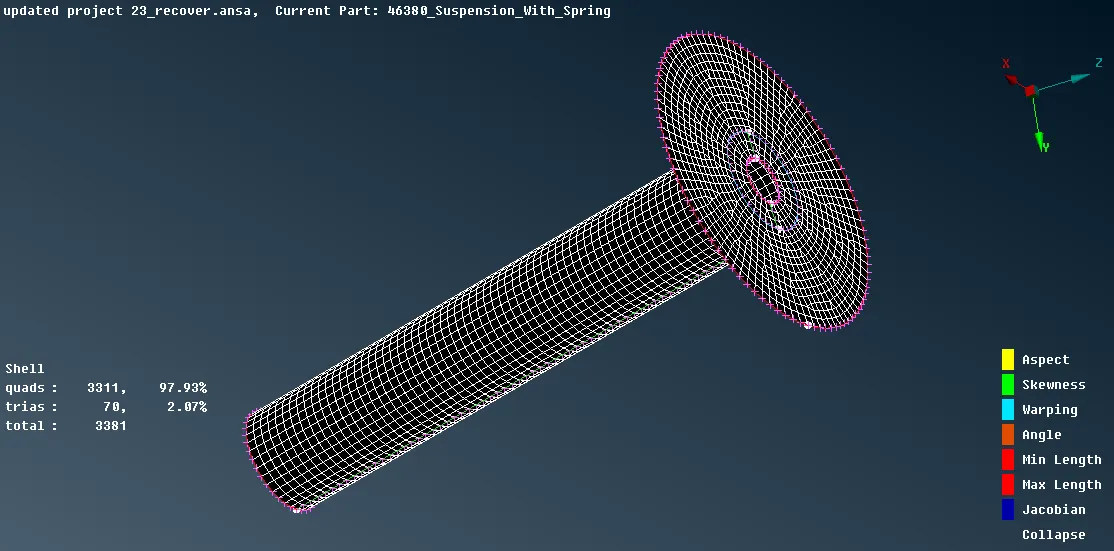
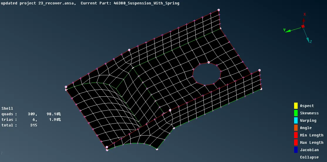
- So after meshing all the entities connection should be provided wherever required.
- Seam Weld Connection
- For the bracket and lower spring seat seam weld can be applied, to apply seam weld first generate a curve on the edge of the bracket by Modules -> Topo -> Curves -> Cons2Curves. After generating curve convert it to seam line by Assembly -> Convert -> Curves -> Select the Curve -> Seam line -> Middle mouse click to accept.
- Now to assign and realize the seam weld connection, Assembly -> connection manager -> select the "seam line" -> middle mouse click -> in connection manager window assign P1 and P2 one by one (right click -> modify -> F1 -> select the part -> middle mouse click -> press enter) -> FE Rep Setting -> FE Rep Type = Overlap Shell, Search Distance= 30, Root Shell= Double row, Step length= 4, Width= 4, Weld PID (to assign shift + /)= create a new PSHELL ID, ok, double click to assign the ID ->Apply -> Realize. The seam weld will be assigned and realized.
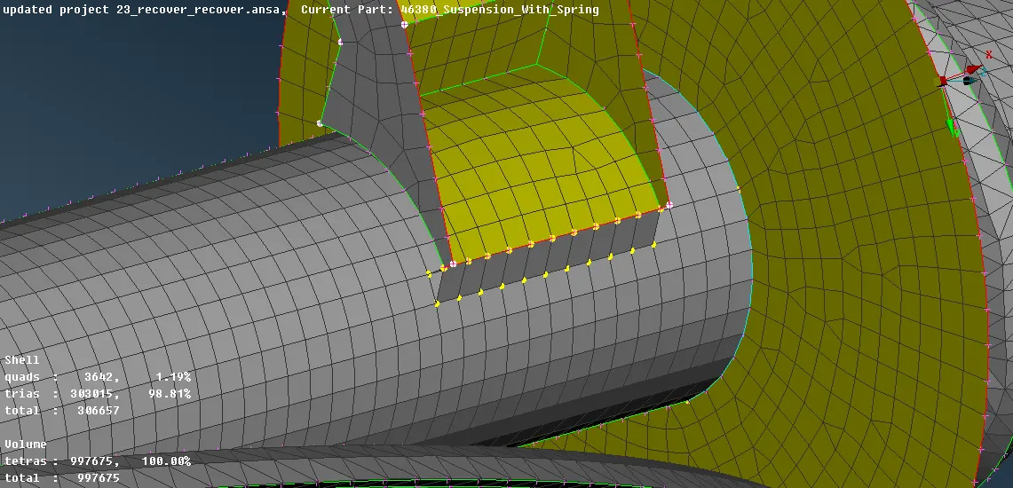
- CBAR
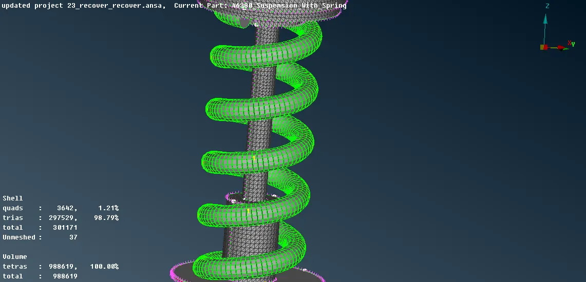
- Cbar elements can be generated for spring, first, a curve is need to generate CBAR which can be created by using Modules -> Topo -> Curves -> Middle -> Select the first cons -> middle mouse click -> Select the 2nd mouse click -> Middle click to generate curve. Convert the curve to one single curve by Module -> Topo -> Curves -> Connect -> Multi -> Select the 2 curves to convert to one curve.
- To generate CBAR elements, Modules -> NASTRAN -> Elements -> CBAR -> Element definition parameter (Pick = Curve (Box)) -> Select the Curve ->middle mouse click -> provide the element length -> enter -> CBAR tab will open, Provide a name, Orient = with vector, Click on X1 and press F1 select the one end node of the curve and other nearby node, click ok -> under lists goto property and select the spring property, rename it, under "A" provide the area or press "shift + /" provide the radius of the spring, ok, ok.
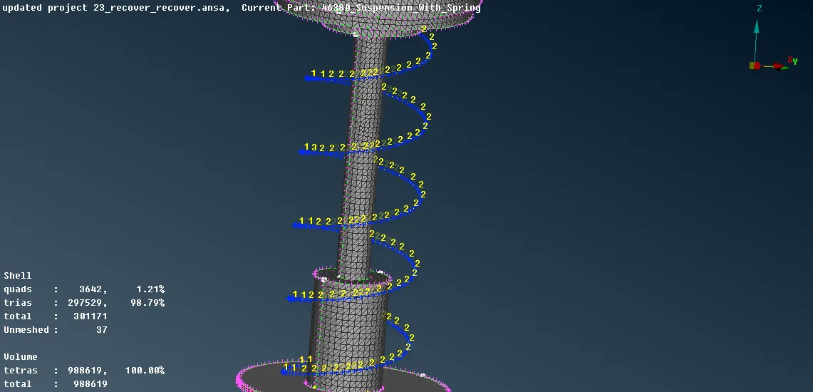
- Enable the Line Element CrossSection and select Draw mode = As Solid present under the Utilities -> Quality Criteria -> Presentation Parameters
- Stem RBE2 As Bolt Connection
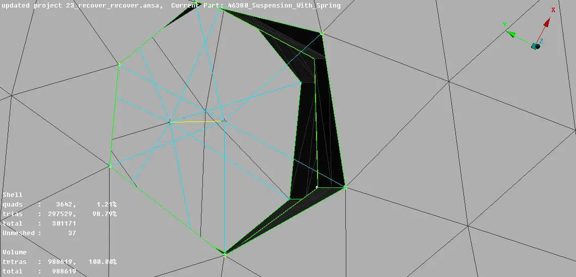
- For 2 matching holes first apply many node RBE2 to the top boundary elements of the top hole by in the modules -> NASTRAN -> Elements -> RBE2 -> Many nodes -> select the nodes of the hole which will be slave nodes (by loop) -> master node will assigned automatically, next -> CM is DoF= 123456, change Part = Ask always -> Finish -> In model browser assign a part by creating a new part -> ok.
- Repeat the same process for bottom boundary elements of the bottom hole.
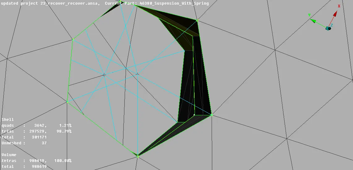
- After creating the RBE2 many node connection on both hole connect the master node of the 2 holes via RBE2 two nodes, by modules -> NASTRAN -> elements -> RBE2 (Two node) -> select the 2 master node -> ok
- Similarly in holes wherever bolt connection is required it can be applied by the above method.
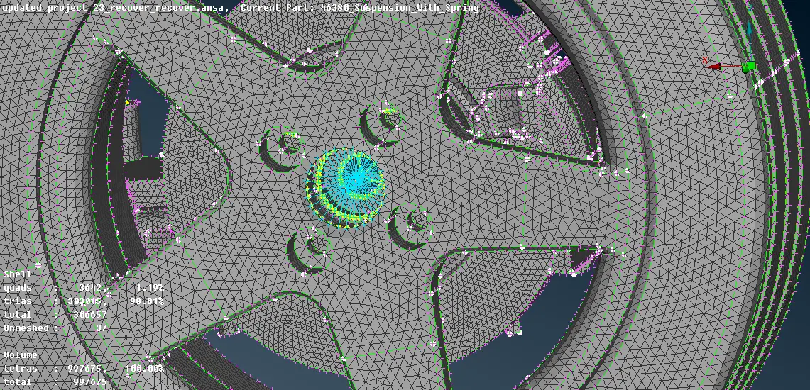
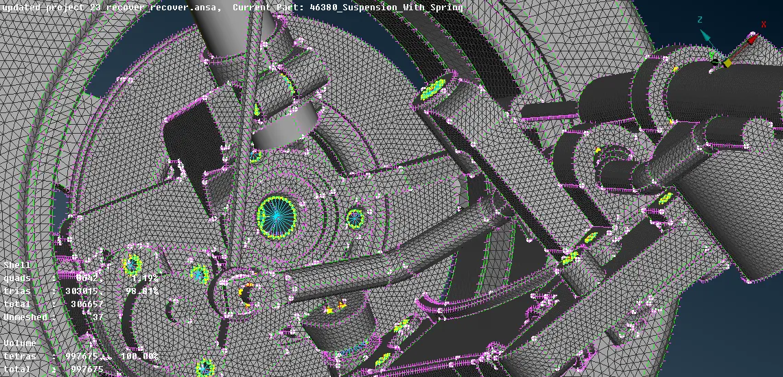
- After completing the mesh and connection copy the entire entity by Utilities -> Transform -> Copy -> select the entities -> Symmetry -> Mirror 3 points plane -> Click on each coordinate and select the point of reference where the copy should be done -> Middle mouse click -> transformation option = ok -> Finish
- Also, Enable Line Element CrossSection and select Draw Mode= As Solid from Utilities -> Quality Criteria -> Presentation parameter.
Result:-
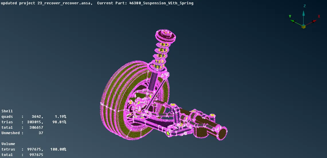
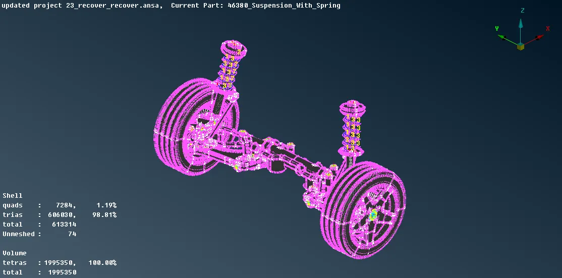
Conclusion:-
So by completing this challenge, I learnt how to perform geometry cleanup and then generate volume mesh and shell mesh according to the given quality criteria for different entities of the suspension assembly also how to resolve the elements failing for quality criteria and also to apply connection to where ever required.