Project 2
AIM
* To check the geometrical errors for the given rear suspension assembly.
* To mesh the model using tetra elements or mixed elements considering the thickness of the components.
* To deploy connections to connect the components.
INTRODUCTION TO SUSPENSION ASSEMBLY
Automotive suspension assembly separate the wheel/axle assembly from the car body. The primary function of the suspension system is to isolate the vehicle structure from shocks and vibrations due to irregularities of the road surface. It is very important to analyse an Automotive suspension assembly for static and dynamic loads. To perform analysis the first task is to discretize the part into finite number of elements which is called Pre-processing or Meshing. ANSA is used for pre-processing Automotive suspension assembly and make the model ready for any Analysis.
A system of springs and dampers that are used to connect the wheels to the chassis is known as the suspension system. It performs a dual job i.e. improves the ride quality as well as keeps the ride more comfortable for the passengers irrespective of the terrain.
Suspension systems are divided into three categories
- Dependent
- Semi Independent and
- Independent suspension system.
Dependent suspension systems:
Dependent systems may be differentiated by the system of linkages used to locate them, both longitudinally and transversely. Often both functions are combined in a set of linkages.
Semi Independent suspension system:
In a semi-independent suspensions, the wheels of an axle are able to move relative to one another as in an independent suspension but the position of one wheel has an effect on the position and attitude of the other wheel. This effect is achieved via the twisting or deflecting of suspension parts under load. The most common type of semi-independent suspension is the twist beam.
Independent suspension system:
Independent suspensions are the suspensions mounted on individual wheels, compared to dependent suspensions, where suspensions are mounted on axle. The biggest advantage of independent suspensions are that motion of single wheel is independent of other wheel. This results in greater performance and in turn, more comfort.
Here is the list of various types of suspension systems
1. MacPherson Strut: A common suspension system, cheaper than other suspension systems.
2. Wishbone, Double Wishbone: A bit expensive than the MacPherson strut.
3. Multilink suspension system involves more linkage then any other suspension system, expensive to produce but is easier to install.
4. Air compressed Suspension system mostly used in heavy trucks, buses and in performance vehicles.
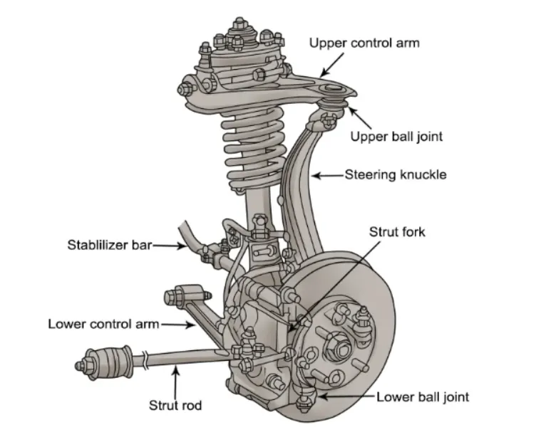
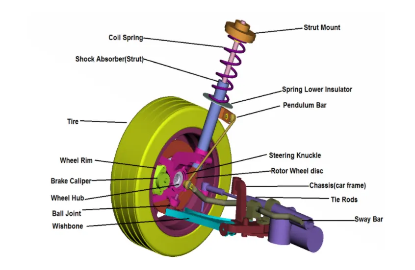
Components of a suspension system
PROCEDURE
- Geometry cleanup and geometry check for provided CAD.
- Thickness measurement at various parts and decide the type of the component.
- Mid surfacing by using various techniques for sheet metal components.
- Surface meshing with provided quality criteria.
- Defining volumes and doing volumetric meshing.
- Solving the failed elements by using mesh improvement tools.
- Deploying connections.
STEPS
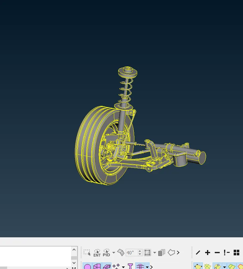
*Import the model using file_open.
*The given model should be analysed properly.
*The model can be disassembled with the help of properties for better understanding.
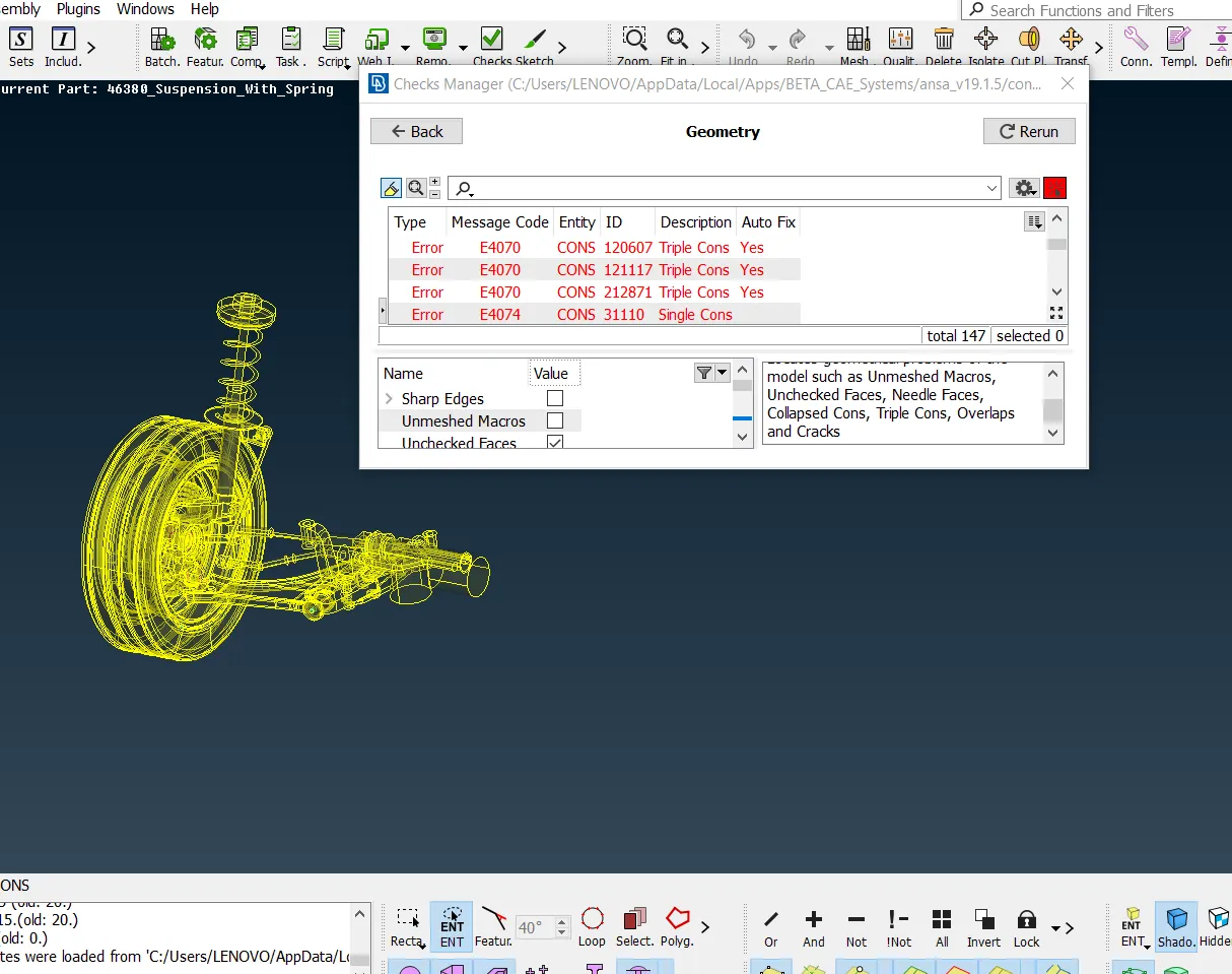
*Apply topo on the selected view and check up the geometry.
*Triple cons is eliminated using release coons and applying topo.
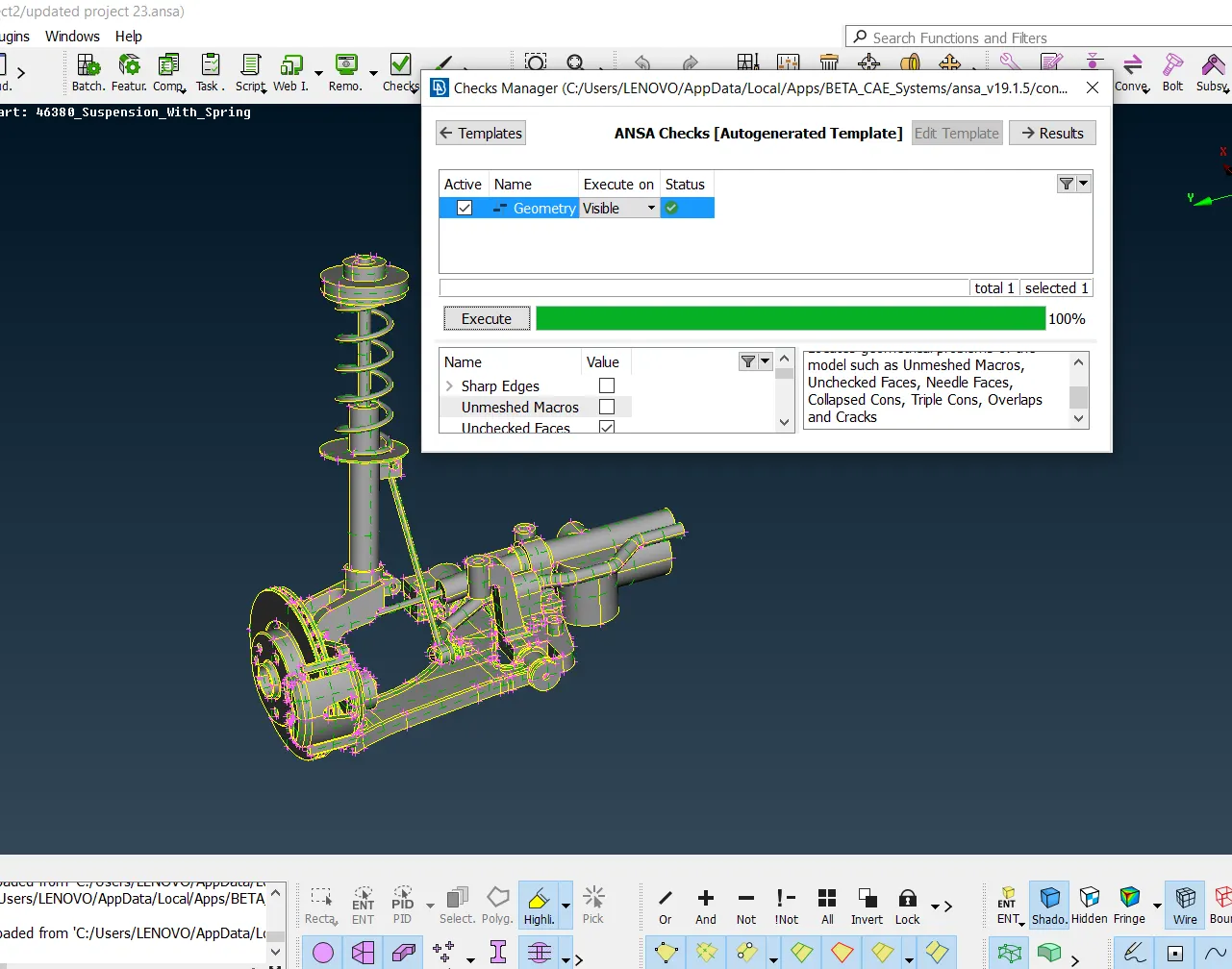
*When it comes to solid mesh, midsurface cannot be generated. So for any component whose cross sectional thickness cannot be measured , solid meshing is done.
* Here for surface meshing spotmesh is followed.
* Element length for a solid mesh will be much lower than shell mesh criteria.
* On meshing initially the quality criteria and mesh parameters should be entered as per the given details as shown below.
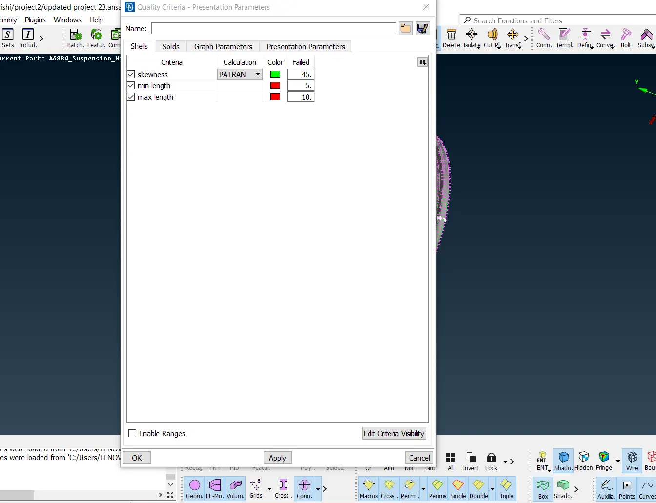
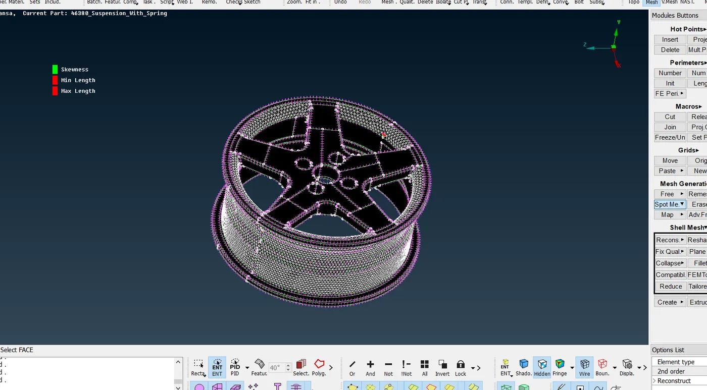
*On surface meshing, each part is meshed using spot mesh as shown below
*The mesh used in a fillet and element type used for any circular or curved like surfaces is ortho tria and for flat surface element type used is tria formation.
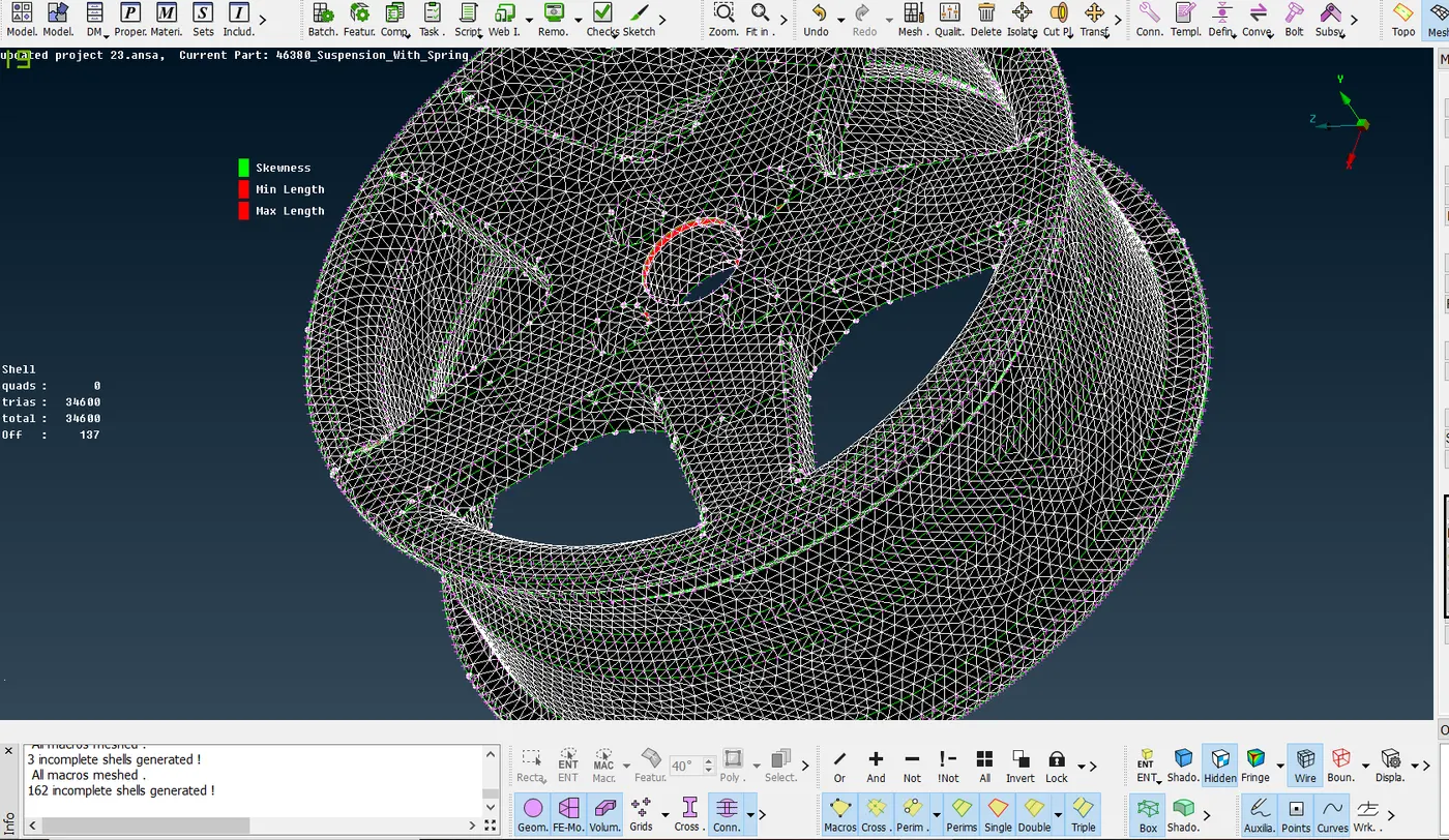
* For volumetric meshing, the part is defined initially and then the mesh is introduced using tetra FEM from Unstructured mesh as shown below.
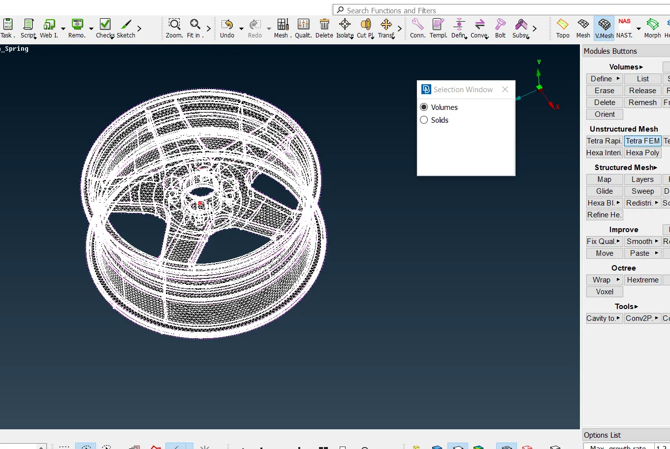
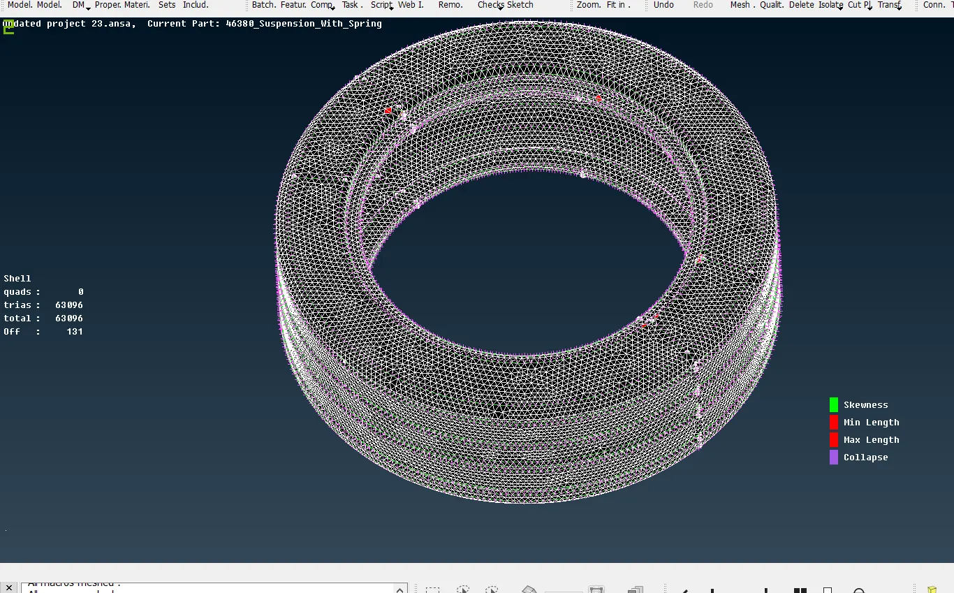
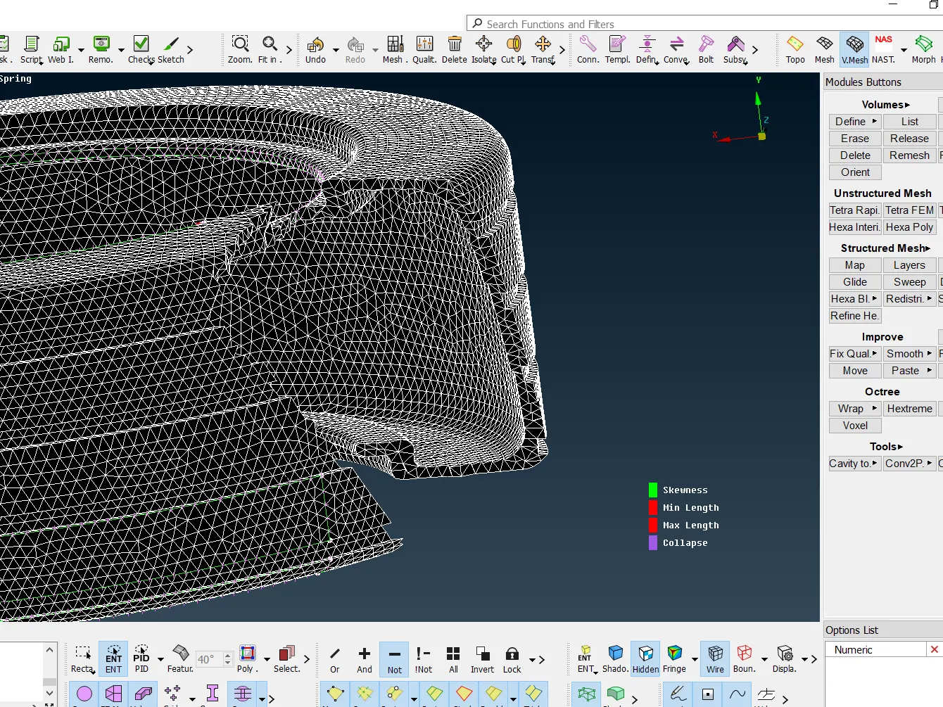
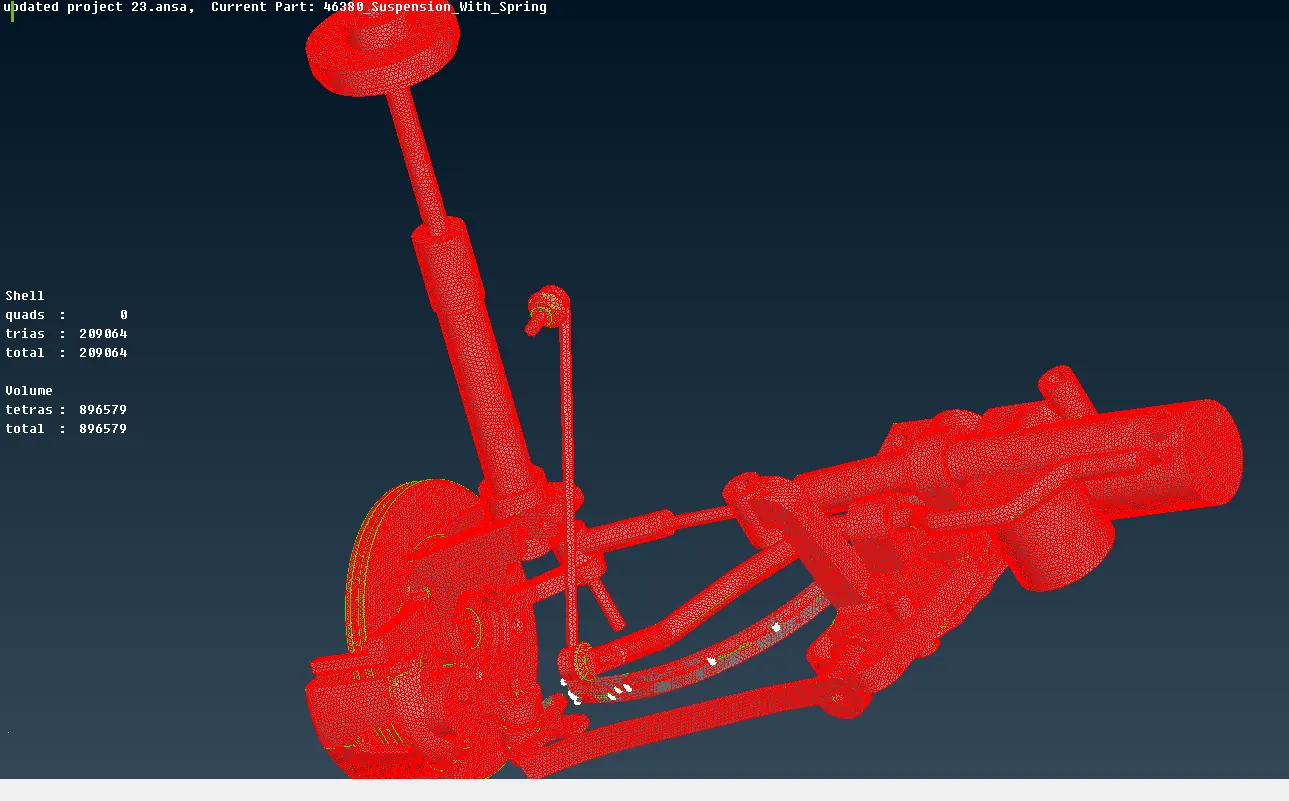
* Shell mesh and volumetric mesh of tyre portion is shown below.
SUSPENSION
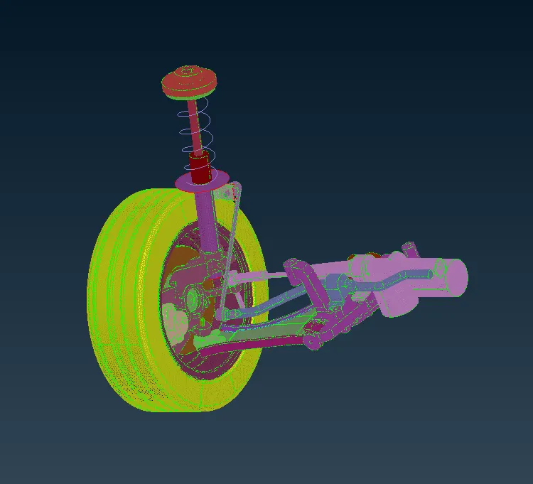
* The suspension consists of different components and so the system is disassembled and each part is defined in different PID.
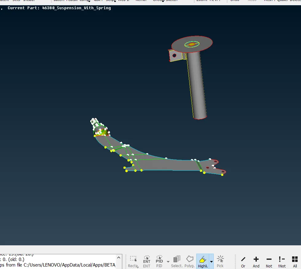
* The components having more than 5mm thickness is taken for surface meshing and below that thickness the midsurface is generated and shell mesh is introduced.
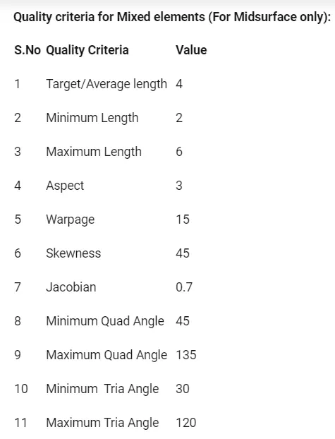
* The bracket, lower arm base and the dis with stem is of low thickness and the midsurface of these components is extracted and taken for shell meshing as per the given quality crieria as shown below.
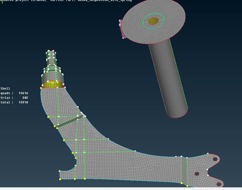
* The other components in the suspension system is of greater thickness and so the components are surface meshed initially and then volumetric meshing is introduced by defining Psolid ID with the help of volumetric mesh deck.
* The quality criteria for shell mesh and volumetric mesh is given below.
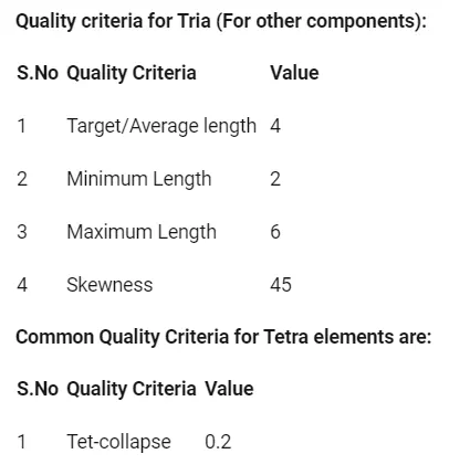
VOLUME MESH
*After generating surface mesh for the solid model using spot mesh, the volume of the model should be meshed.
*Solid meshing is of two types:
1)Tetra mesh or Unstructured mesh
The tetra elements has 4 nodes as shown image.
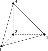
* The tetra elements follows the surface mesh for first layer of mesh and generate meshing for the entire volume without following any pattern and so called Unstructured Mesh.
Tet Collapse
*Tet Collapse is the most important Quality criteria which is always checked while Tetra mesh is Performed (Tet Collapse is applicable to Tetra Elements only).
*As we know that Tetra element is a four noded element which has four sides and four nodes as shown in image below.
This is the method of solving Tet Collapse without disturbing the surface quality.
-
For this, Isolate the failed elements and do Neighbour 1st level. (By doing Neighbour 1st level we can see the neighbour elements which are connected with isolated elements)
-
Click on MV Free and select a Node which can be moved such that the height of the Tetra element can be increased.
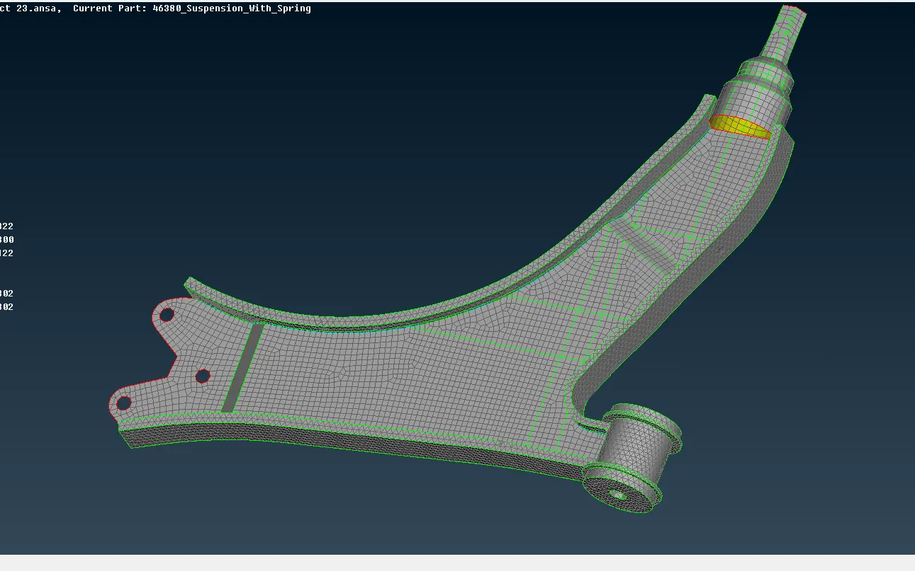
* Here as per the below shown image, the lower arm base if of lower thickness and it is shell meshed whereas the the side face and cylinder is solid meshed.
*The shell mesh should be properly connected to the voume mesh of the side faces and the cylinder as shown below.
*The lower base con and hotpoints are projected to the adjacent faces and followed by pasting the nodes with the help of paste option from grids in mesh deck.
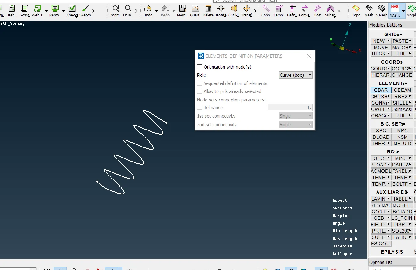
* The coil spring is represented in 1D element by introducing CBAR with the help of NASRAN deck.
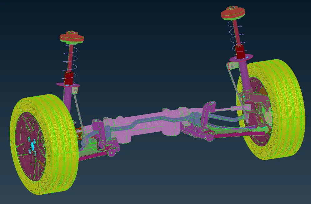
SUSPENSION ASSEMBLY
CONNECTIONS
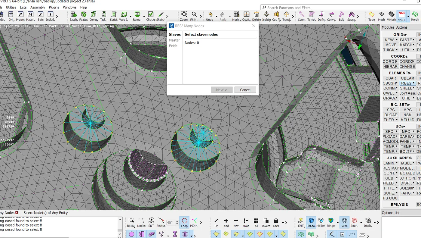
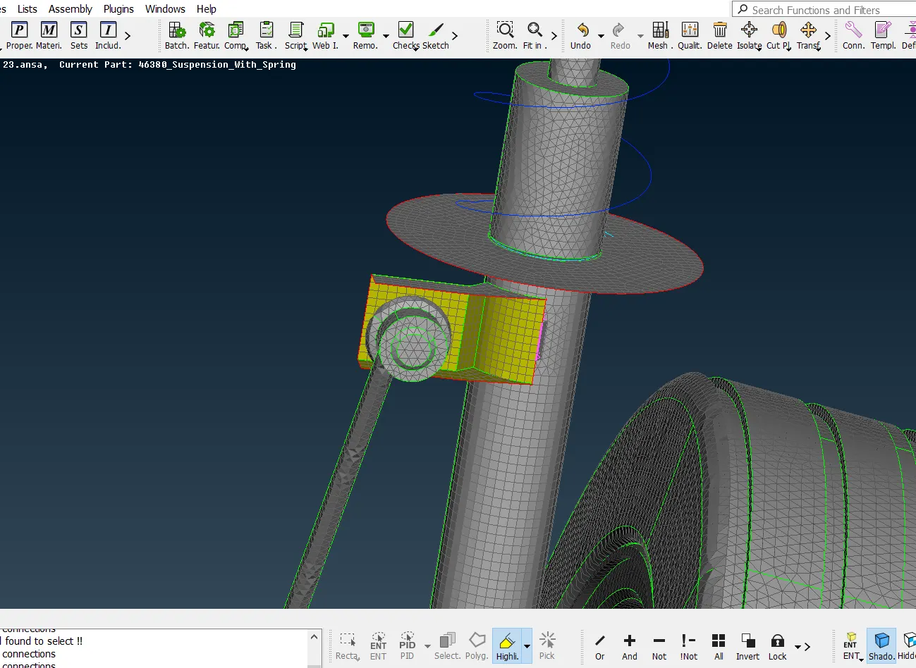
* In this model RBE2 and seam weld connections are done as per shown below.
* RBE2 connections are provided on the the bolt areas of the geometry before analysis
*RBE2 many node connections are done between the rim and hub, hub and knuckle as shown below
* The bracket is attached to the stem of the damper by introducing a seam weld.
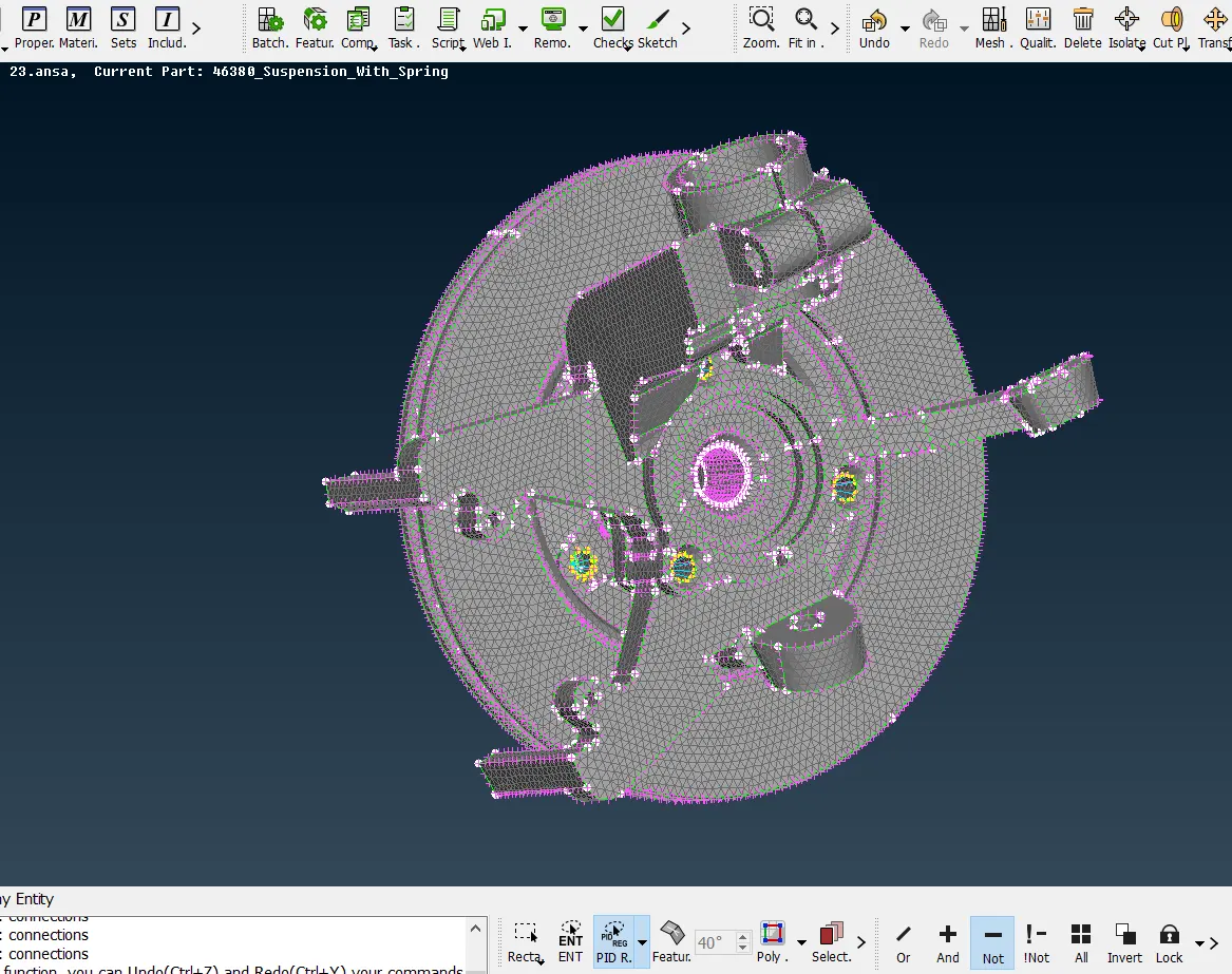
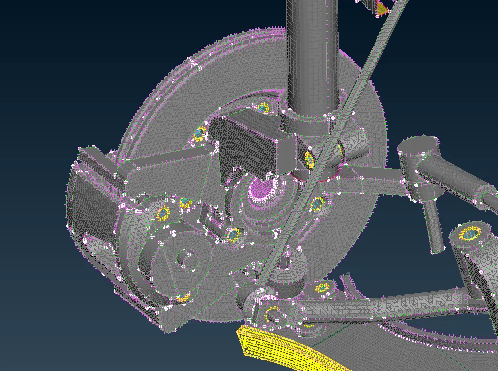
* After deploying all sort of connection in the appropriate areas TRANSFORM< COPY is given selecting the whole entities and a symmetry is obtained.
REAR SUSPENSION ASSEMBLY
ERRORS AND CORRECTION
*The below shown component represents the solid mesh of the wheel hub and on visualising the elements in the splines of the hub are failing for quality.
*The reconstruction of the mesh for better quality leads to the distortion of the feature.
*Here the failing elements should be restricted without defeaturing the splines.

CONCLUSION
* The components of the suspension system are captured with solid elements(tetra) and shell element(quad & tria) considering the given quality criteria.
* In preprocessing meshing and connections are significant as it helps in the flow of stress evenly throughout the model.
* When it comes to solid mesh, midsurface cannot be generated. So for any component whose cross sectional thickness cannot be measured , solid meshing is done.
* Element length for a solid mesh will be much lower than shell mesh criteria.
* The curved areas are mainly captured by using ortho tria elements while surface to capture the best of its f features.
*Appropriate bolt connections are given using cluster RBE2 under NASTRAN deck.