Bird Strike - Project - 2
Introduction:
A bird strike refers to collision between an aircraft and a bird. It mostly occurs at the low altitude or on the ground i.e. runways during take-offs and landings. With the increase in number of annual flights, Birdstrike incidents have also increased.
Bird strikes on aircraft mostly occurs during take-off or landing stages as the large open fields surrounding the airports provides perfect feeding, nesting and resting areas for large species of birds. Most common part of aircraft where bird strike can occur is the engine followed by leading edge (wing and empennage), windshield, nose and fuselage.
Various methods are implemented by airport authorities to keep these birds away from the runways like remote bird sensors and hand-held laser devices for detection of birds during flight operations.
Bird strike testing by manufacturers involved firing a bird carcass from a gas cannon onto the tested unit. Later the carcass was replaced my suitable density blocks, often gelatine to ease testing.
Objective:
Experimental testing of aircraft engines is associated with high costs and long development times. The usage of new composite and hybrid metal reinforced composite structures in engine components requires extensive testing.
In order to reduce the reliance on physical testing that slows the development, new computational approaches for assessing the bird strike crashworthiness of advanced engines are needed.
The goal of this project is to develop a numerical methodology to examine the damages and failure of an aircraft engine subjected to bird impact.
The work is focused on scenarios where a bird directly impacts the rotating fan assembly since this presents the most destructive impact scenario.
In this task, we follow gm-mm-ms unit system which is consistent throughout the project.
Significance of Bird strike analysis:
Birdstrike is a major threat to commercial aviation with about 90% of all foreign object damage cases are related to birds. Majority of bird strikes cause little damage to the aircraft; however, the collision is fatal to the birds involved.
Most accidents occur when there is a collision involving a bird (or birds) and the windscreen or a bird (or birds) is sucked into the engines of the aircraft. In addition to property damage, collisions between manmade structures and conveyances and birds is a contributing factor among many others, to the worldwide decline of many avian species.
Newer turbofan engines used in commercial aviation feature larger inlet diameters to achieve higher bypass ratios and greater fuel efficiency. This larger forward-facing area for each engine have a great chance of ingesting birds.
Current testing is mainly conducted with computer simulation, although final testing usually involves some physical experiments.
Modelling Aero-engine with Bird-strike setup in LS-DYNA:
LS-Dyna is a general purpose transient dynamic finite element program capable of simulating complex real-world problems.
It is an explicit 3-D finite element program for analyzing the large deformation dynamic response of the elastic and inelastic solids and structures. The program is extensively used by many top automobile, aerospace and research organizations.
The contact capabilities such as contact between deformable bodies, between deformable and rigid bodies provided in LS-Dyna can solve any contact problems which very useful in crash testing.
Geometries such as regular cylindrical, spherical, ellipsoidal and cylinder with hemispherical ends are typically used to model the bird. In advanced research experiments, researchers sometime model the bird structures such as with distinct head, neck and wing portions.
In our case, the bird is modeled with cylindrical shaped mesh with shell elements that reduces the cost of computational time and gives adequate results.
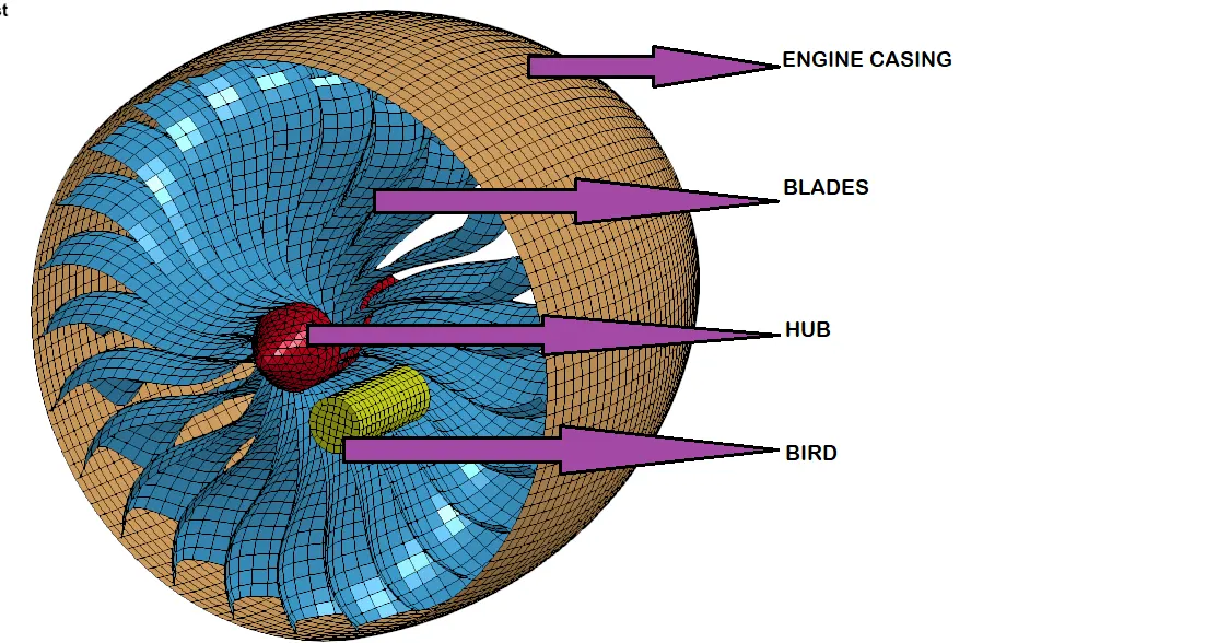
The meshed bird-strike model setup is provided with four parts namely 1.Engine casing 2.Blades 3.Hub and 4.Bird.
The whole setup is divided and saved into individual parts and they are used for the analysis using *INCLUDE card later.
Renumbering IDs:
Each part of the model setup is opened in LS-Prepost individually and their node,element and part IDs are renumbered accordingly in a such a way that 100000+ for nodes, 500000+ for elements, and 1000+ for the parts. This method follows a consistent numbering approach which is used commonly in industries that deals with complex projects.
| Element ID range | Node ID range | Part ID | |
| Engine casing | 500000 to 503967 | 100000 to 104095 | 1001 |
| Blades | 503969 to 509441 | 104096 to 110348 | 1002 |
| Hub | 509442 to 530285 | 110349 to 114330 | 1006 |
| Bird | 530286 to 530695 | 114331 to 114742 | 1004 |
A main keyword file which is used for referencing all the parts only using *INCLUDE_INCLUDE card one by one.
The control cards, contact cards and boundary conditions are defined in a separate keyword file that includes the main file referencing all individual parts.
Material modeling setup:
The parts of the bird-strike model setup are modelled with different materials to create the expected scenario.Blades are connected to the central hub thus forming a rotating sub structure.
The Hub is a thick component when compared to the fan blades and is not likely to experience damage or failure because the fan blades will fail before damaging loads were transferred to the hub. Hence the hub stresses are not determined, and it was assigned with rigid steel material properties.
The engine casing and hub are modeled with rigid material as they do not account for any deformation in the model during the event.
The blades are modeled with Titanium material properties with the Young's Modulus as 112500 MPa using *MAT_PLASTIC_KINEMATIC material model.
The bird is modeled with an elastic material with 2000 MPa as Young's modulus.
Section modeling setup:
It can be seen that the bird, blades and engine-casing are made up of shell elements but the hub is made up of solid elements.
Using *SECTION_SHELL card, all the parts, except the hub, are modeled with shell element formulation.
Similarly, the hub is modeled with *SECTION_SOLID card with tetra-hedron element formulation.
Contact modeling setup:
Contact are defined between different parts to avoid penetrations during the impact scenario.
In case of bird impacting the fan blades directly, it is important to assign the proper contact between
• Bird and fan blades,
• Fan blades and hub,
• Fan blades with other blades,
• Blades with themselves.
*CONTACT_AUTOMATIC_NODES_TO_SURFACE is defined between the bird and blades with slave part as blades and master part as bird. It is defined in such a way that blade failure is likely to occur which is our part of interest.
Similarly *CONTACT_AUTOMATIC_NODES_TO_SURFACE is also used between the bird and engine-casing.
*CONTACT_AUTOMATIC_SURFACE_TO_SURFACE is defined between the blades and casing to avoid penetrations and intersection to happen if any between them.
Boundary conditions setup:
The blades along with the hub are set to rotation with constant velocity using *INITIAL_VELOCITY_GENERATION card. An angular velocity omega=4.0 is given as the input for the blades.
The bird is set to move in the impacting axis direction with a constant translational velocity of 100 mm/ms using *INITIAL_VELOCITY_GENERATION card.
In the *CONTROL_TERMINATION card, a simulation runtime of 1ms is defined in the ENDTIM option.
The results and output files are requested from the *DATABASE card.
Model checking and solving the setup:
One of the most important pre-processing tasks is to ensure the validity of a CAE model before submitting it to the solver for analysis.
A good and rich suite of checks reduces engineering errors, increases the confidence in the simulation results, and minimizes the duration of a simulation cycle by eliminating multiple back and forths from the solver to the pre-processor.
Several errors have been encountered while solving the problem setup such as element intersection and penetration errors due to the attachment of hub and blades.This error is removed by renumbering the node IDs of individual parts.
To achieve a proper simulation such as occurence of blade material failure, several trial and errors of material modeling for blades had been undergone.Also, choosing proper constant angular velocity for blades is practised.
After getting cleared up with the errors if any, the crash box simulation setup is saved.
The saved keyword file is set to run in LS-DYNA manager.
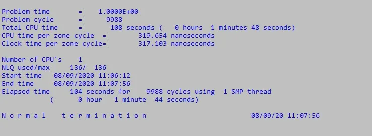
A normal termination of the setup is achieved and the results are analyzed for post-processing.
Post-processing results:
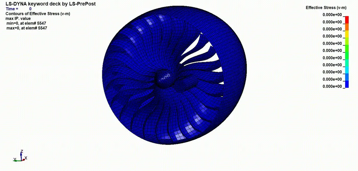
Effective Stress contours:
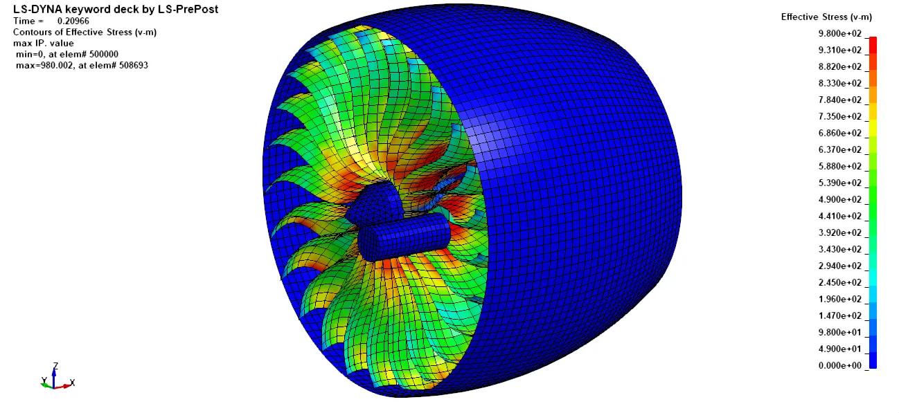
As the fan blades rotates, centripetal forces acting on each fan blade pull it towards the hub centre and maintain its circular path around the axis of rotation. This induces stresses that are greatest at the base of the blade and decrease gradually along the length of the blade becoming zero at the tip.
In order to predict damage, it is necessary to assess stress and strain in the blades because of both bird impact and the initial stress field caused by the fan assembly rotation
Energy plots:
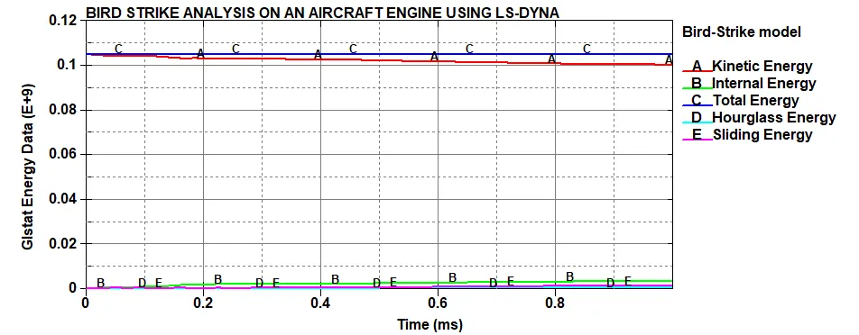
The above plots of graph gives us the information about the energy distribution of bird impacting the engine blades.
It can be seen that at short period of time, the bird hits the engine blades, from which the blade material failure likely occurs.
Correspondingly, the kinetic energy of the system tends to behave in an opposite manner to the internal energy.Thus, decreasing with respect to time.
Since the model is computed with considering the sliding and hourglass effects during the energy distribution, there occurs a slight increase in contact energy between the bird and blades.
Total energy is the sum of all other energies. Hence, the total energy of the system decreases relatively with respect to time.
Conclusion:
It can also be concluded that the computational methodology can be used for certification as it is less time consuming and less expensive when compared to physical testing.
Different types of bird models can be used for testing and results can be compared to find out which model gives the best results. Also, some parameters such as EOS, cavitation pressures can be varied and results can be compared.
Composites material can be applied to the blades and the tests can be carried out and results can be compared.
Different types of computation methods including the Lagrangian, Eulerian, ALE can be used other than SPH and results can be compared.
Finally, the birdstrike simulations can be carried out on different parts of an aircraft including fuselage, leading edge, empennage and windshield, etc.