MESHING AND ESTABLISHING CONNECTION TO SUSPENSION SYSTEM
AIM:- To perform mesh and deploy connection to the suspension system in automobiles.
PROCEDURE:-
- First, we need to import the model to ansa software.
- Then after we need to clean up the geometry.
- Then we need to set components into different property IDs.
- Then we need to decide to perform volume or shell mesh to the component.
- After meshing the component we need to make connections.
GEOMETRY CLEANUP:-
-
We need to import the model from drive to ansa by using
File →open → select file → ok
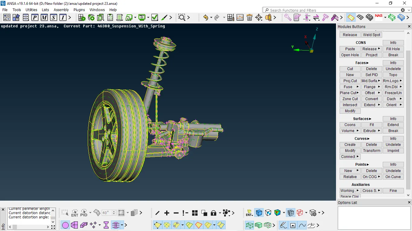
Fig 1:- model imported to ansa
-
- we need to perform topo to entire which will stitch the need node and from one surface
topo module → faces → topo → select model → enter/middle mouse click
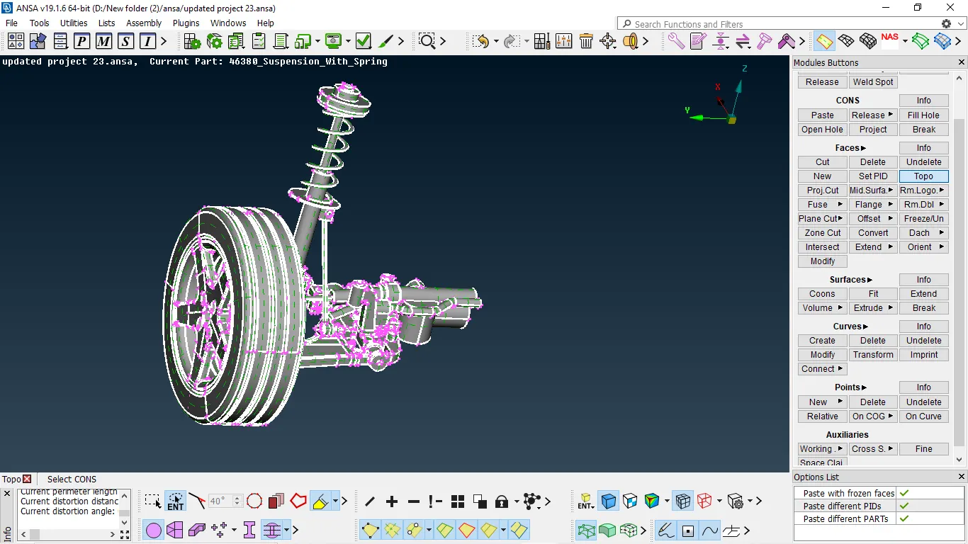
Fig 2:- performing topo
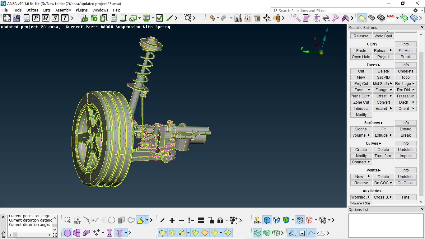
Fig 3:- After performing topo
- After performing topo the lot of triple cons that are wrong we clean up by using geometry checks.
- Then after check the geometry by using the geometry checks option in the tool
- Select all entities and the press execute, then it might show some errors
- Se must clean up those errors by using auto fix or manually
tools/toolbar → checks → geometry → all entities → execute
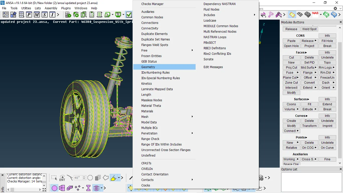
Fig 4:- Going to check geometry
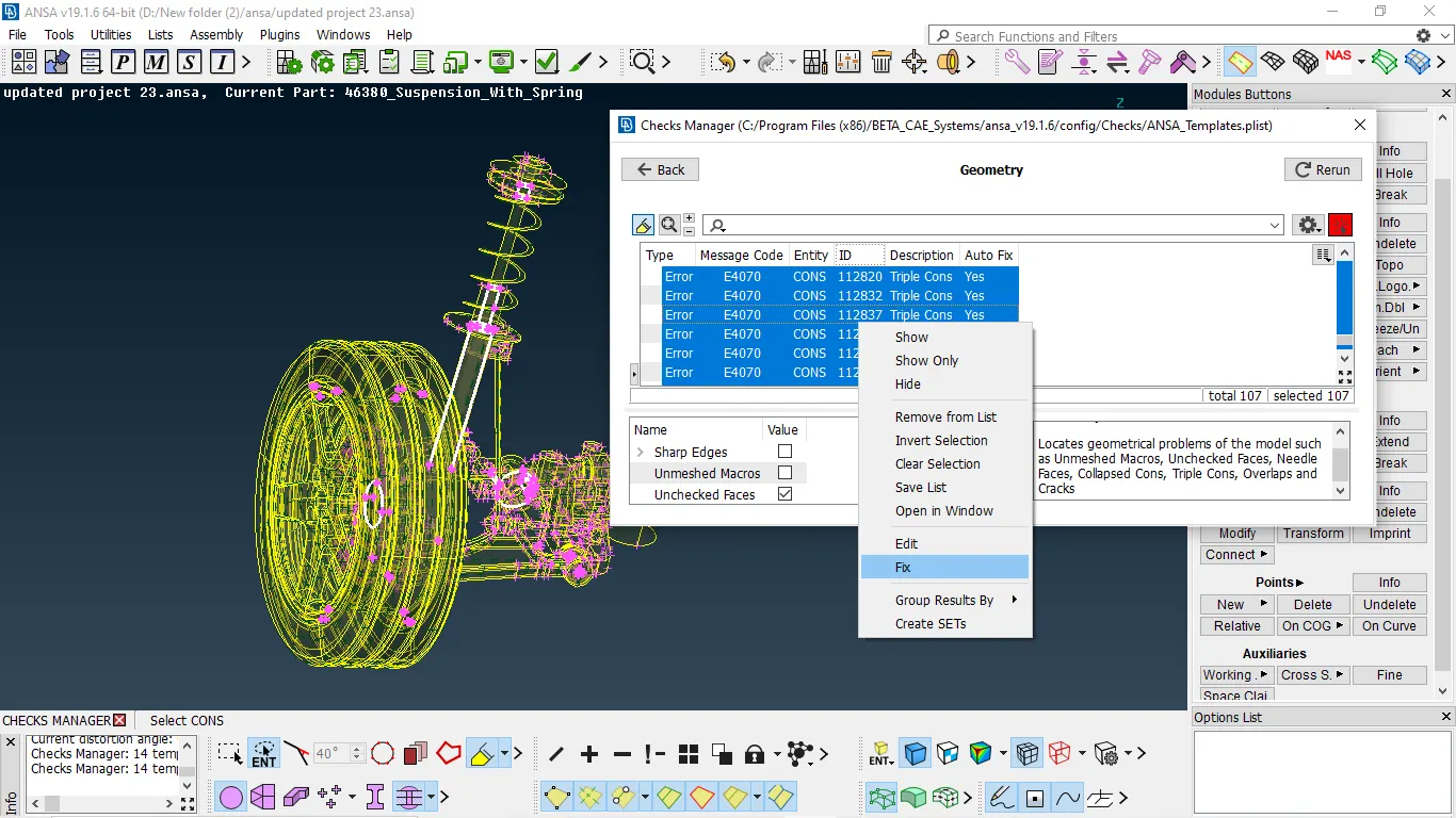
Fig 5:- Errors occurred after geometry checks and fix it automatically
- We need to fix it manually
- By selecting them all make them show only after that we need to fix errors
- Majorly this is triple con errors due to duplicate surface or attachment done to the neighboring surface
- To delete those errors we need to delete duplicate surfaces or we need to release it from attachment to the neighboring surfaces.
TRIPLE CONs DUE TO DUPLICATE SURFACES
- To delete the triple con error we need to delete duplicate surface.
- If there is a patchy surface in geometry then there is a duplicate surface we need to delete them.
- After deleting the surface we need to stitch it will topo because after deleting the surface the connection will be deleted
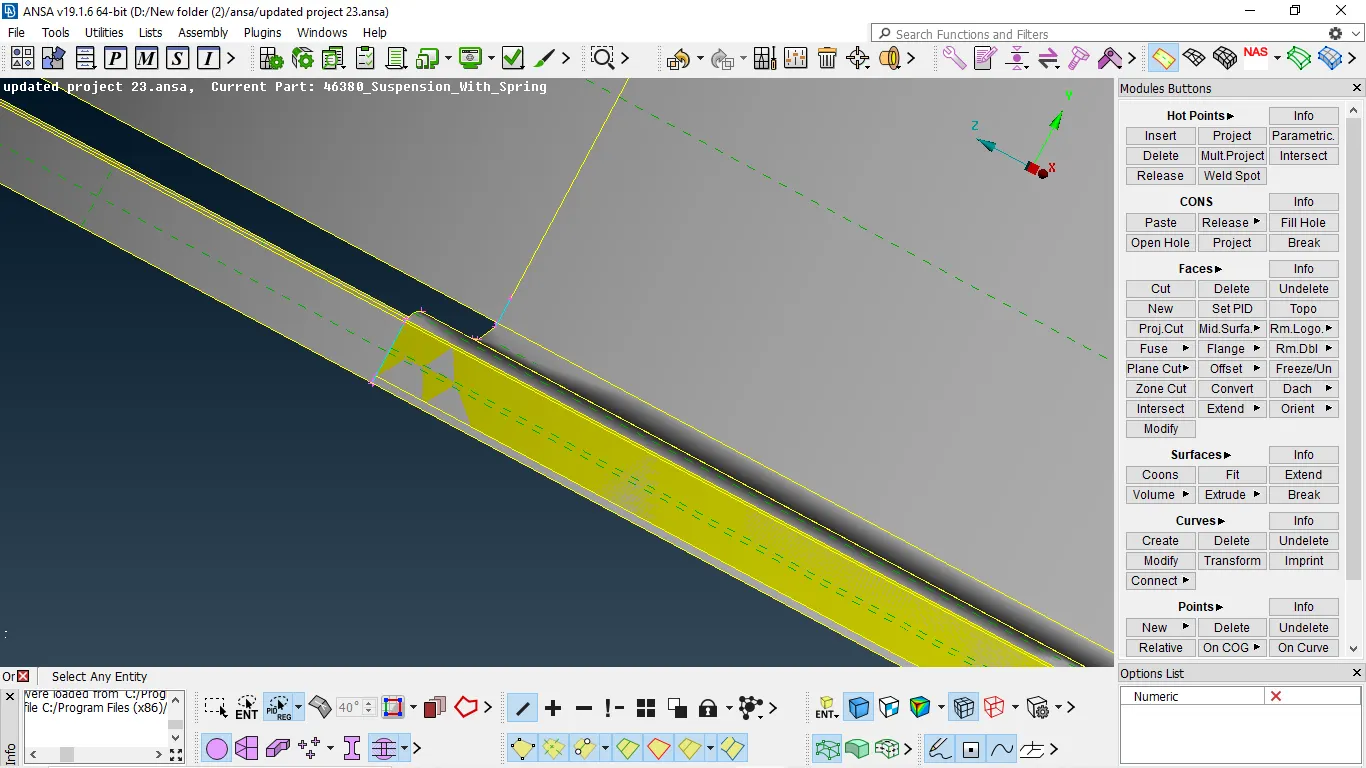
Fig 1:- duplicate surface forming a triple con
TO delete face
Faces → delete → select the face → enter
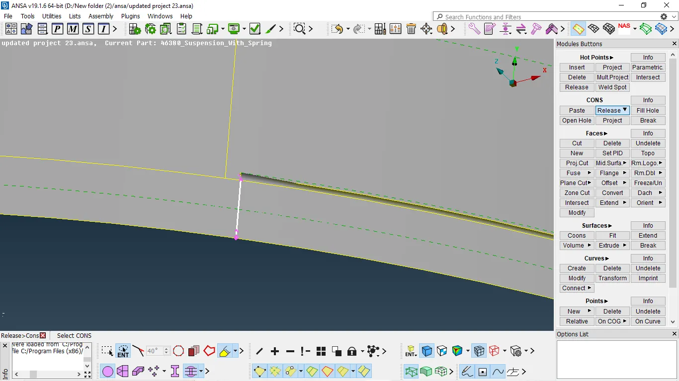
Fig 2:- Releasing the triple con
- After deleting the surface also connection will be triple con so we need to release and paste them.
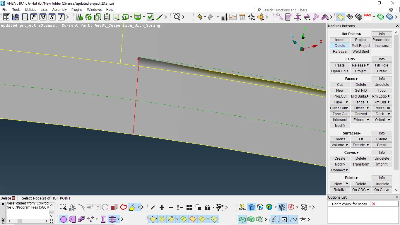
Fig 3:-After releasing the triple cons
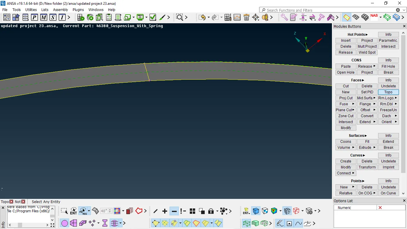
TRIPLE CON DUE TO IRREGULAR ATTACHMENT OF SURFACES
- This is triple con errors due to duplicate surface or attachment done to the neighboring surface.
- To delete those error we need to release.
- After releasing delete unnecessary hotpoints and patch the surface properly.
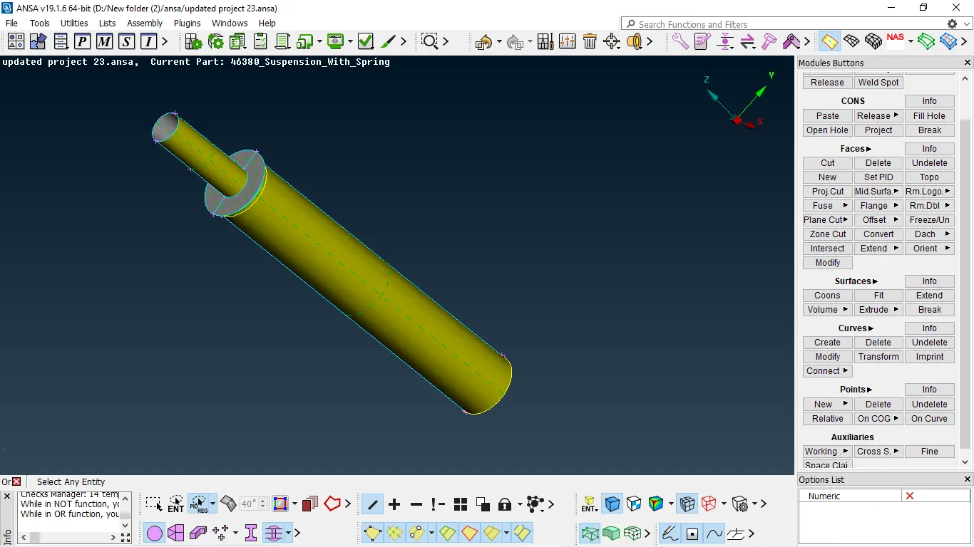
Fig 1:- component with triple cons
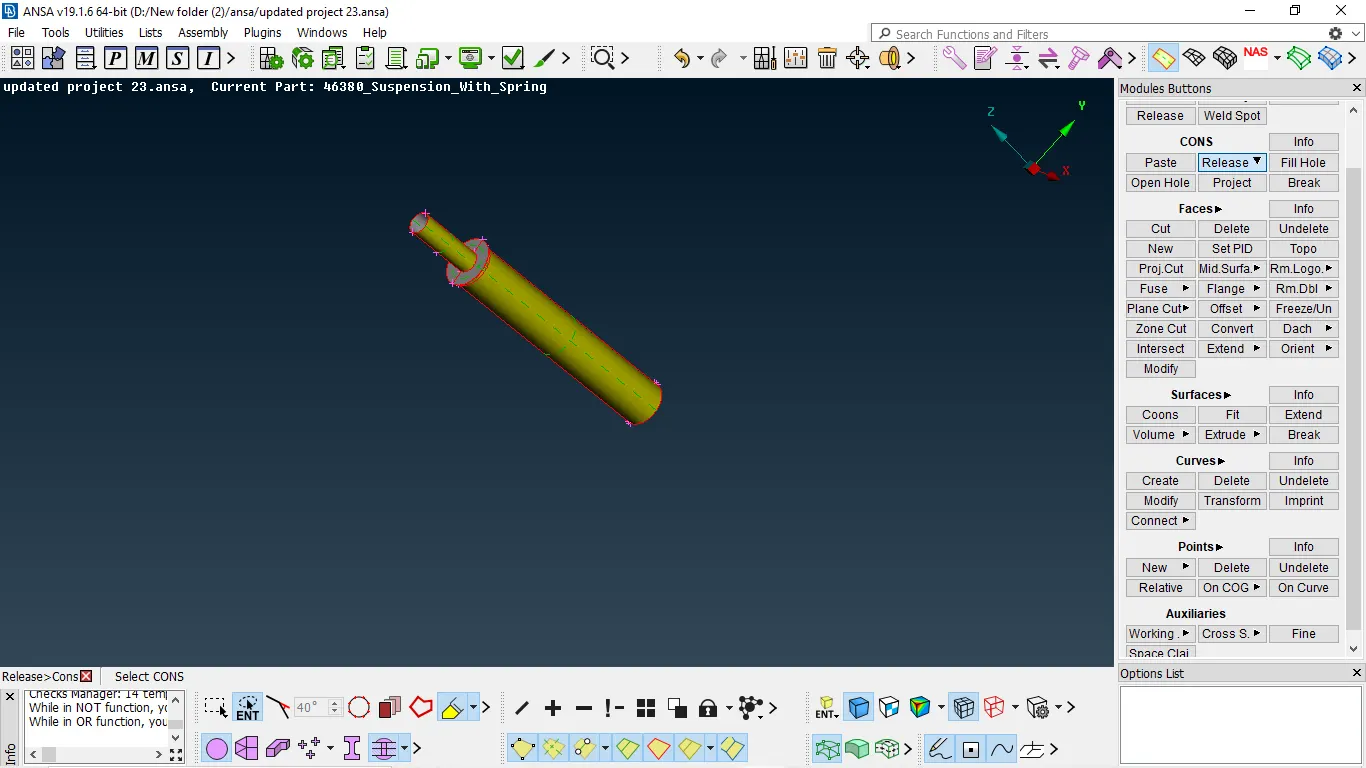
Fig 2:- component after releasing the cons
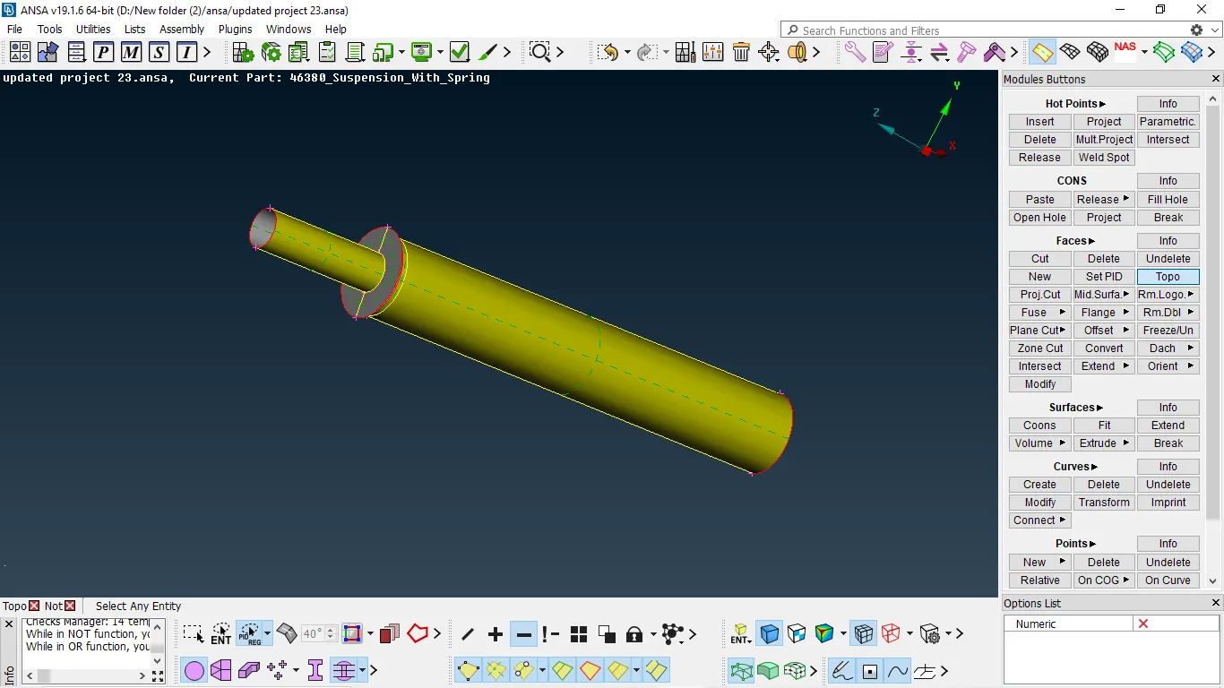
Fig 3:- component after releasing triple con errors.
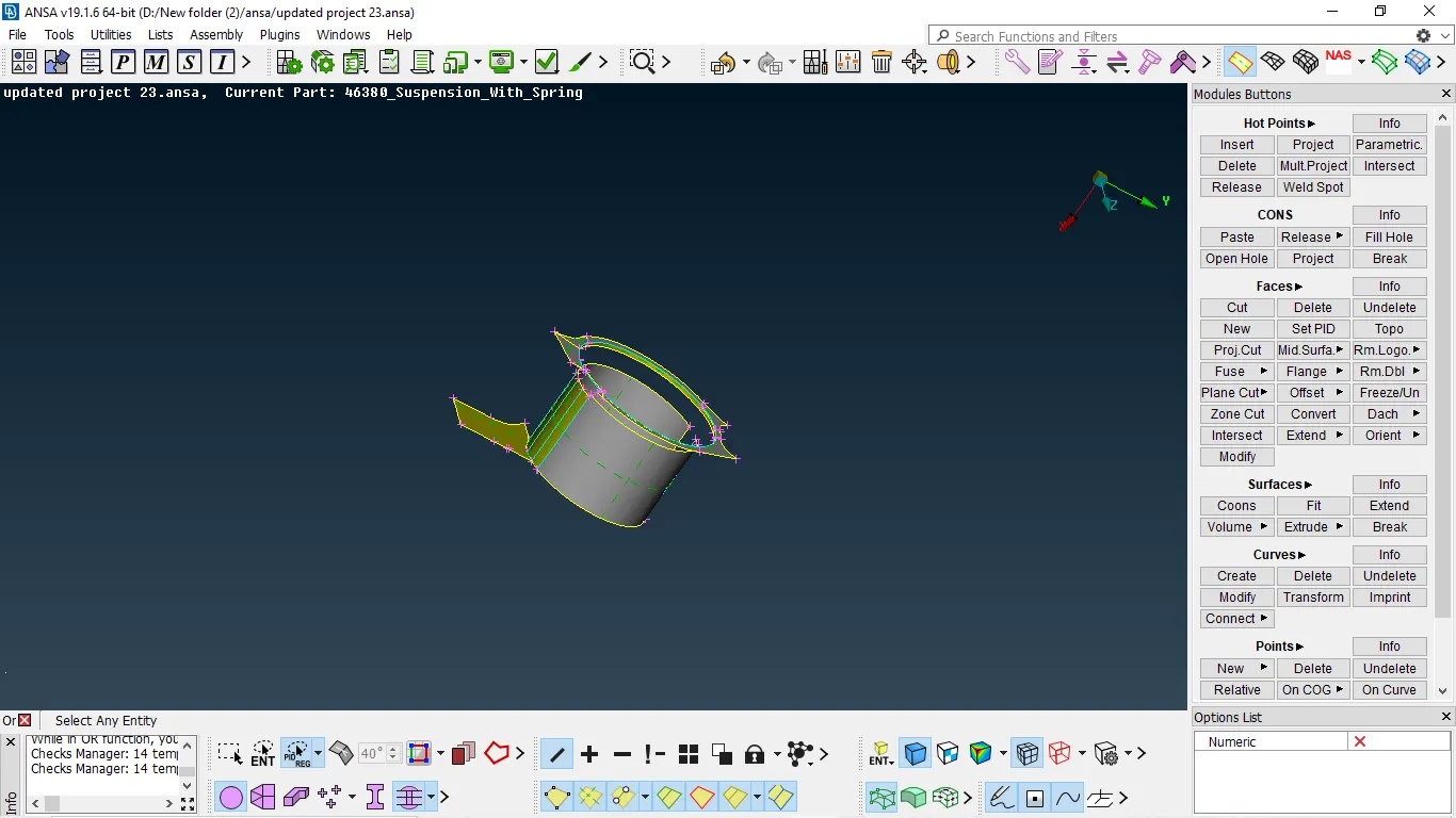
Fig 4:- component with triple cons
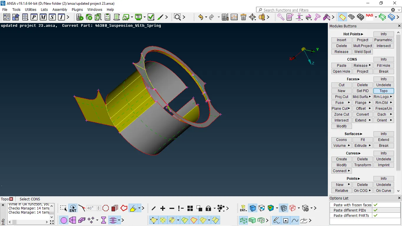
Fig 5:- component after releasing triple con errors.
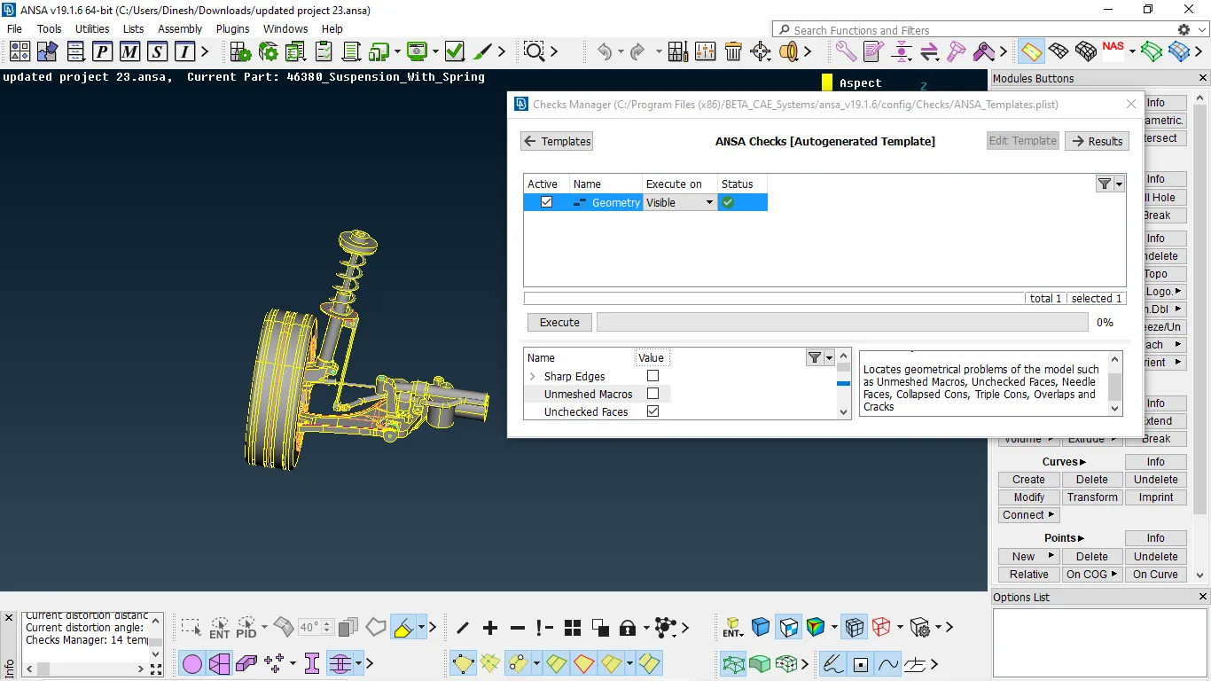
Fig 6:- Geometry clean done successfully
MIDSURFACE:-
- At the start, we need to measure the thickness of every feature.
- The major area of the component less than 5mm must take mid surface.
- The other component must perform volume mesh.
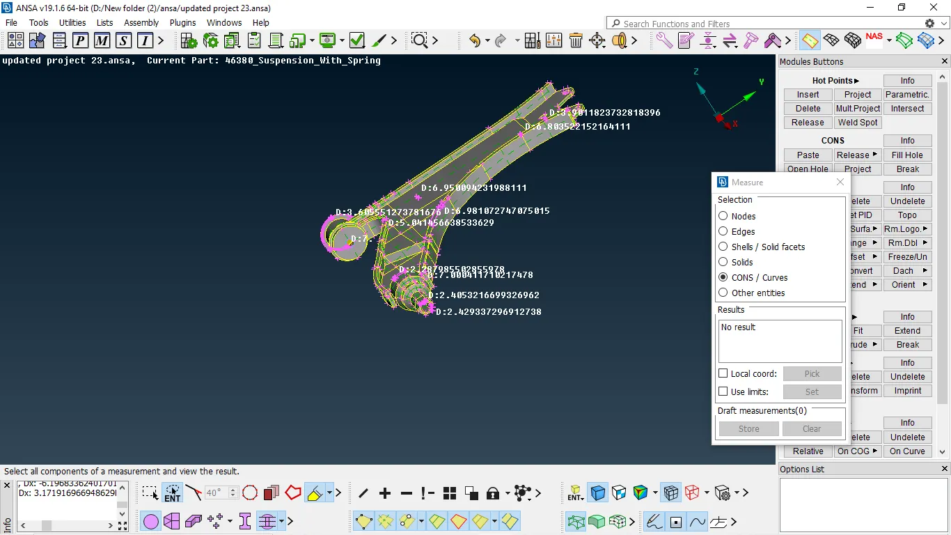
Fig 1:- component 1 thickness measured
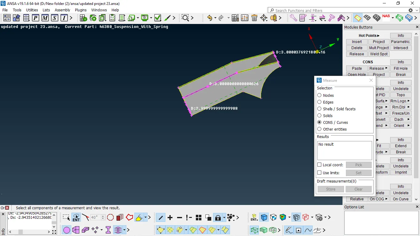
Fig 2:- component 2 thickness measured
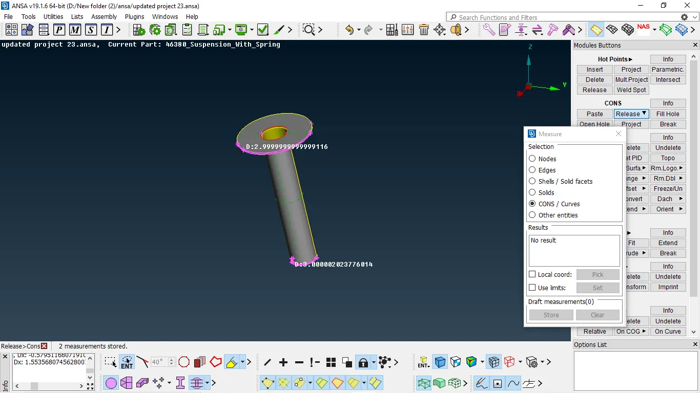
Fig 3:- component 3 thickness is measured
MANUAL MIDSURFACE:-
There are many ways to extract mid-surface some of them are by using middle, offset in faces, and middle curve for complex shapes
- We use offset for surface majorly flat and having constant thickness
OFFSET THE SURFACE
- Measure the thickness → then select offset in faces → select the faces to be offset → give the value of the thickness → middle mouse
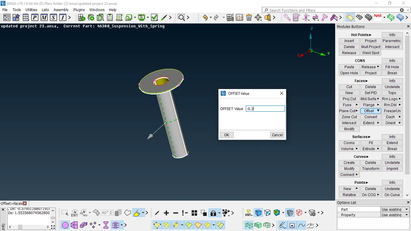
Fig 1:- Taking offset to the component
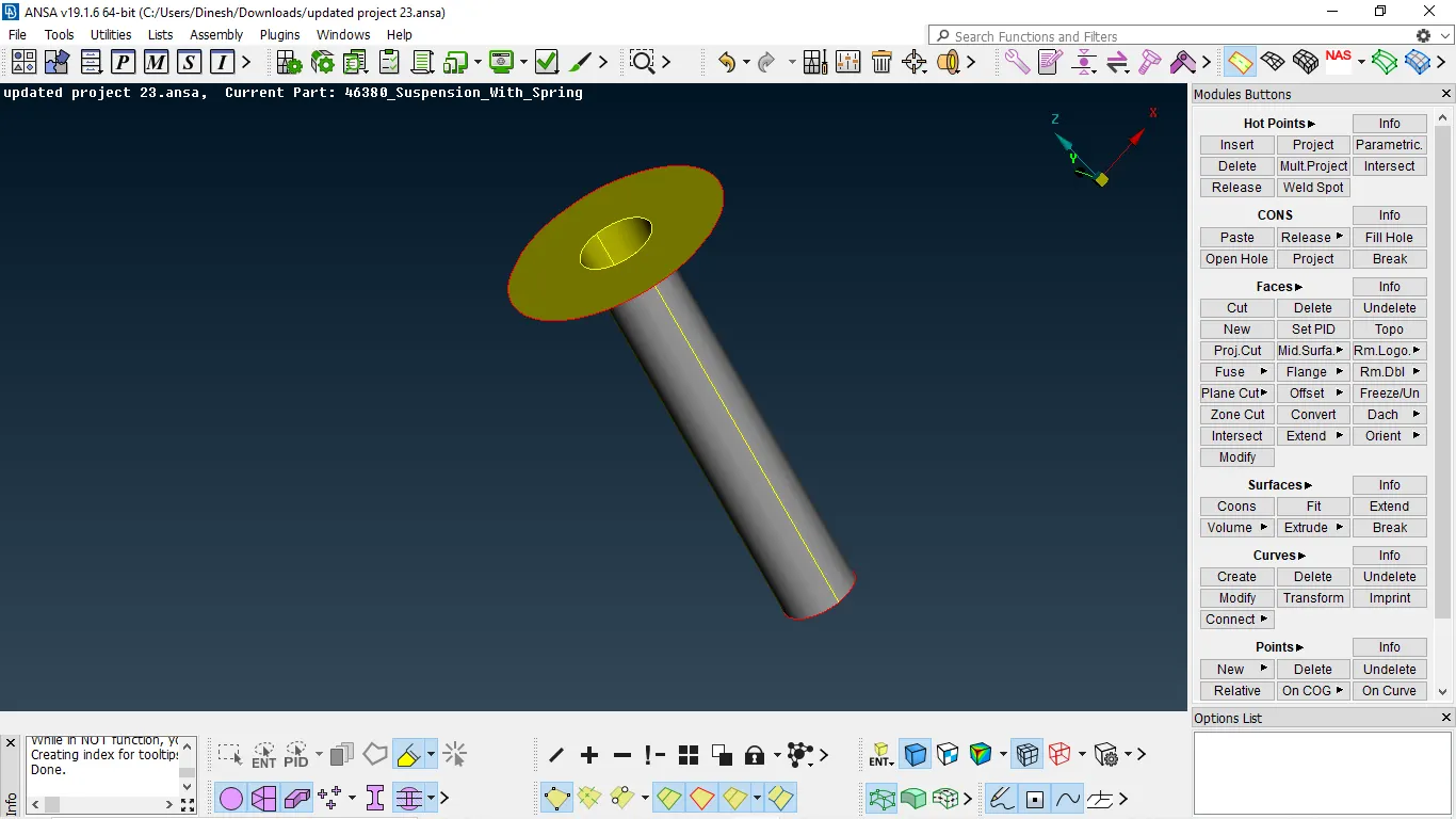
Fig 2:- Offseted component
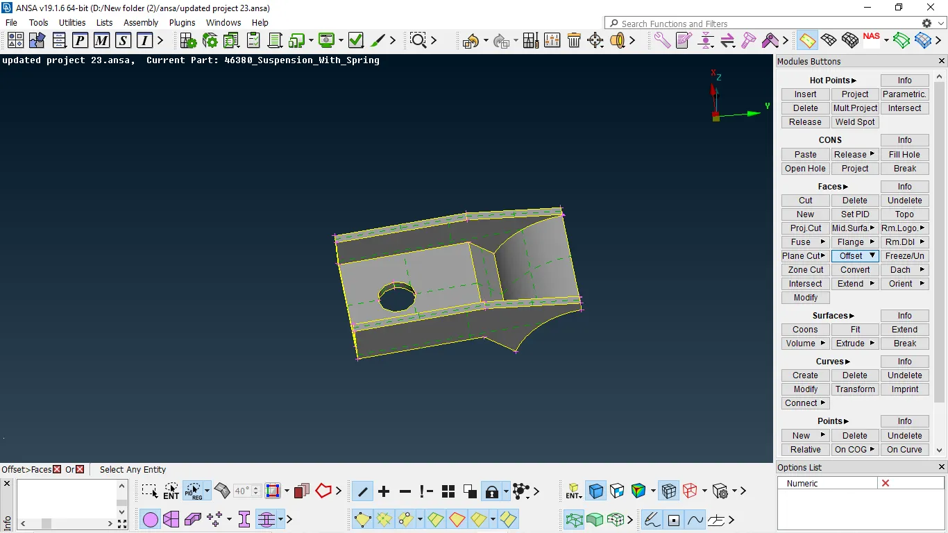
Fig 3:- component to be offsetted
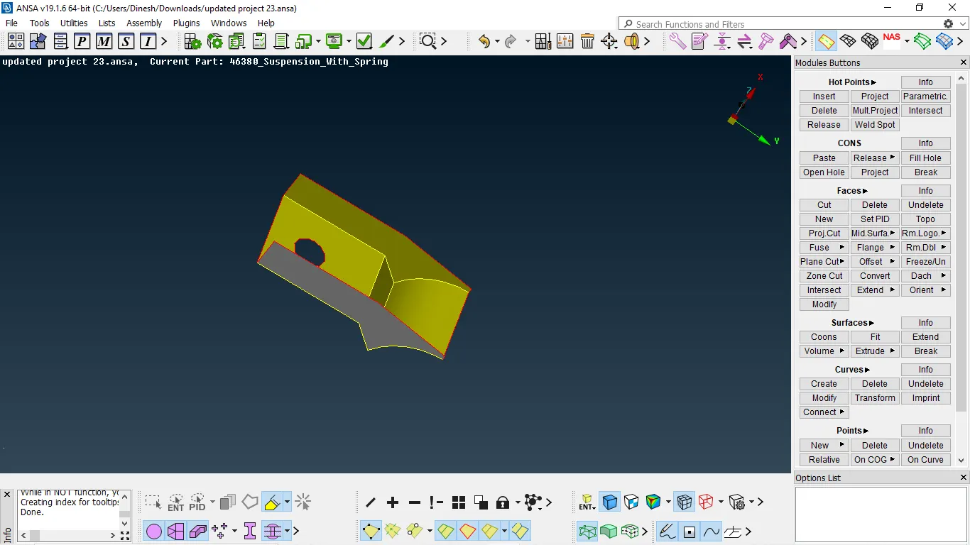
Fig 4:- offesetted component
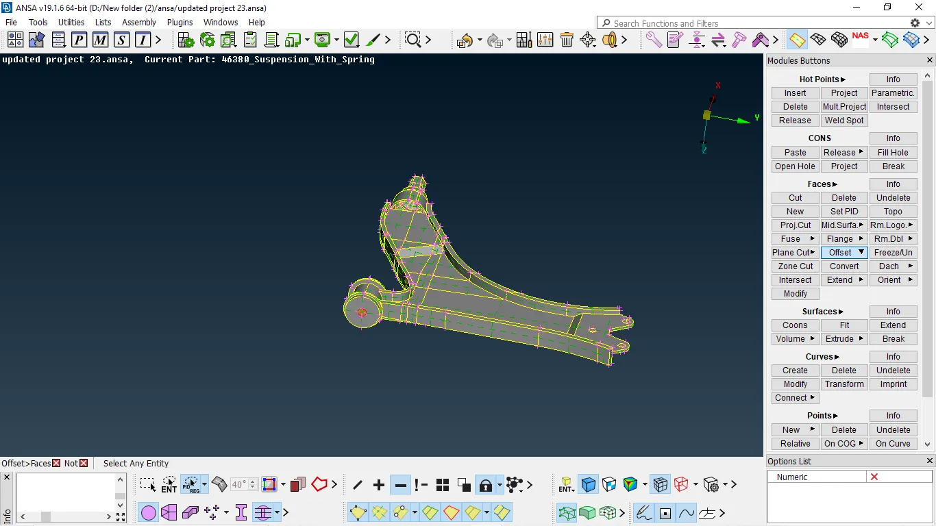
Fig 4:- component to be offsetted
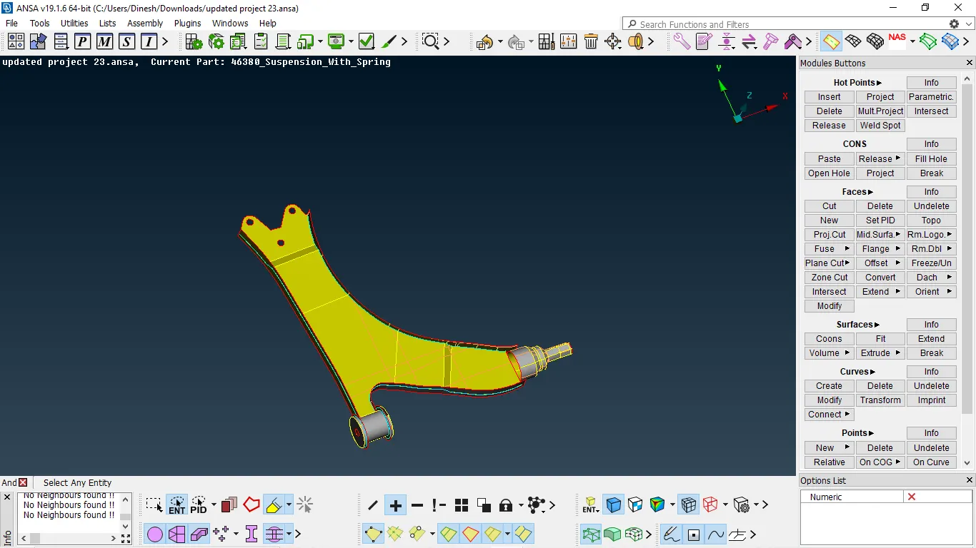
Fig 5:- offesetted component
- The other component must be done volume mesh because they having variable thickness and thickness greater than 5mm
DEFEATURING:-
- Defeaturing is a part of meshing.
- Defeaturing is done to satisfy mesh with respect to quality criteria.
- The fillet which is less than min element length must be defeatured.
- There are two methods to defeature one is dach and the other is divide faces.
- Dach will delete the fillet and form a sharp edge.
- Divide face will capture the feature perfectly without any deviation.
- Majorly we divide faces to capture the area.
- It is recommended to divide the component into different parts it will help to defeature and mesh them easily.
- Before doing defeaturing we need to keep components in different property IDs.
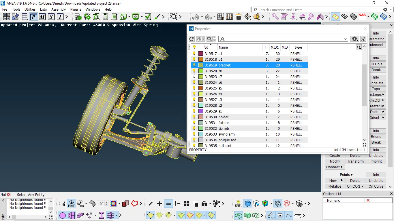
Fig 1:- components kept in different PID with assigning thickness
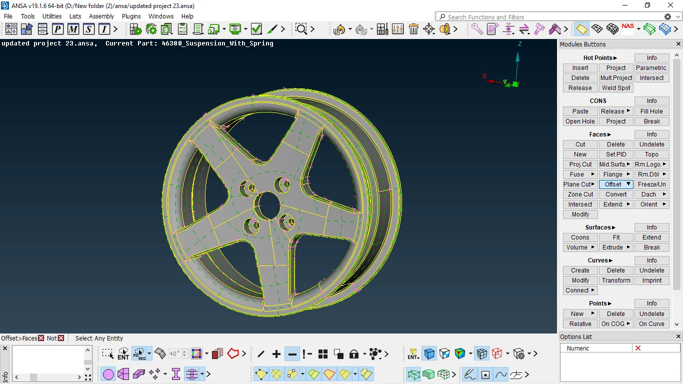
Fig 2:- component before defeaturing
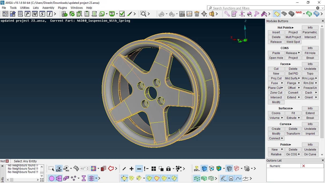
Fig 3:- component after defeaturing
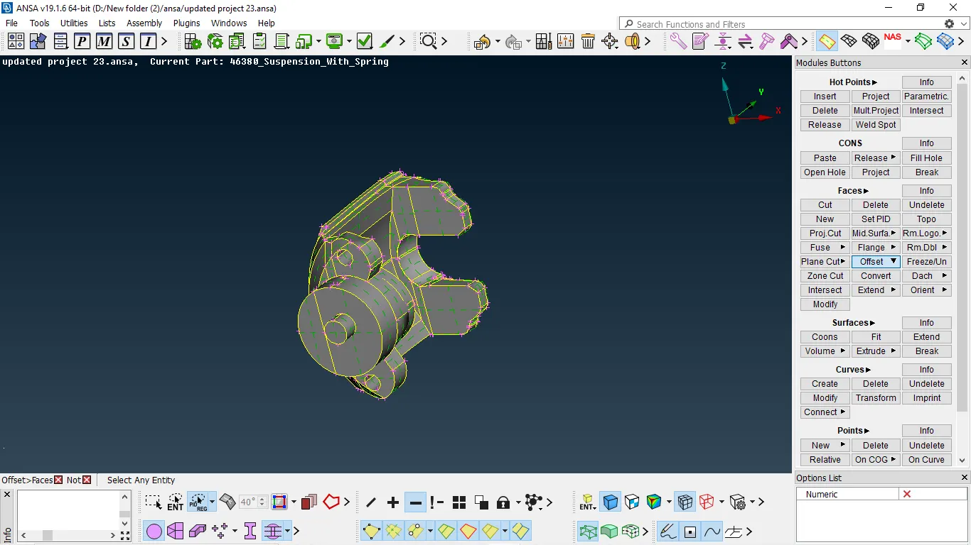
Fig 4:- component before defeaturing
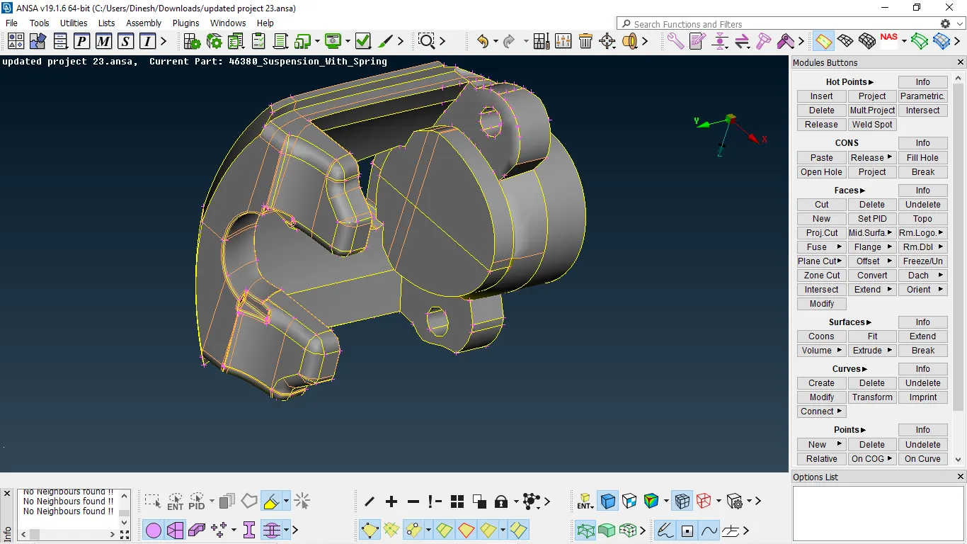
Fig 5:- component after defeaturing
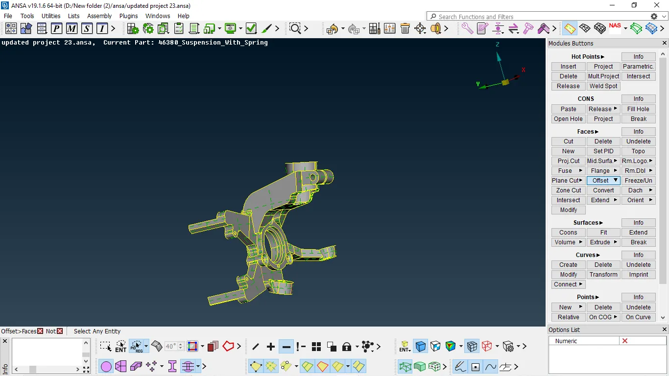
Fig 6:- component before defeaturing
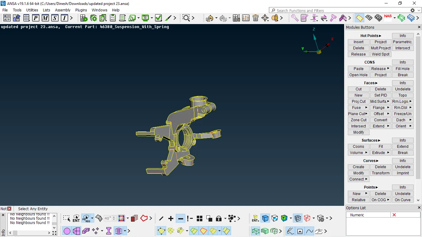
Fig 7:- component after defeaturing
MID SURFACE EXTRACTION
There are many ways to extract mid-surface some of them are by using middle, offset in faces, and middle curve for complex shapes
- We use offset for surface majorly flat and having constant thickness
MESHING:
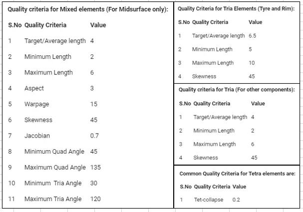
- For every meshing, we need to assign quality as mesh parameters
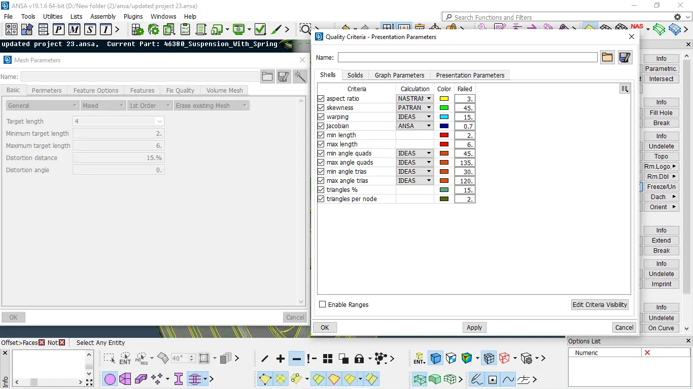
SHELL MESHING
-
We need to give perimeter and macro length every individual part with respective given parameters
mesh module → perimeter → length → select the surface → select perimeter /macros → enter the value → enter
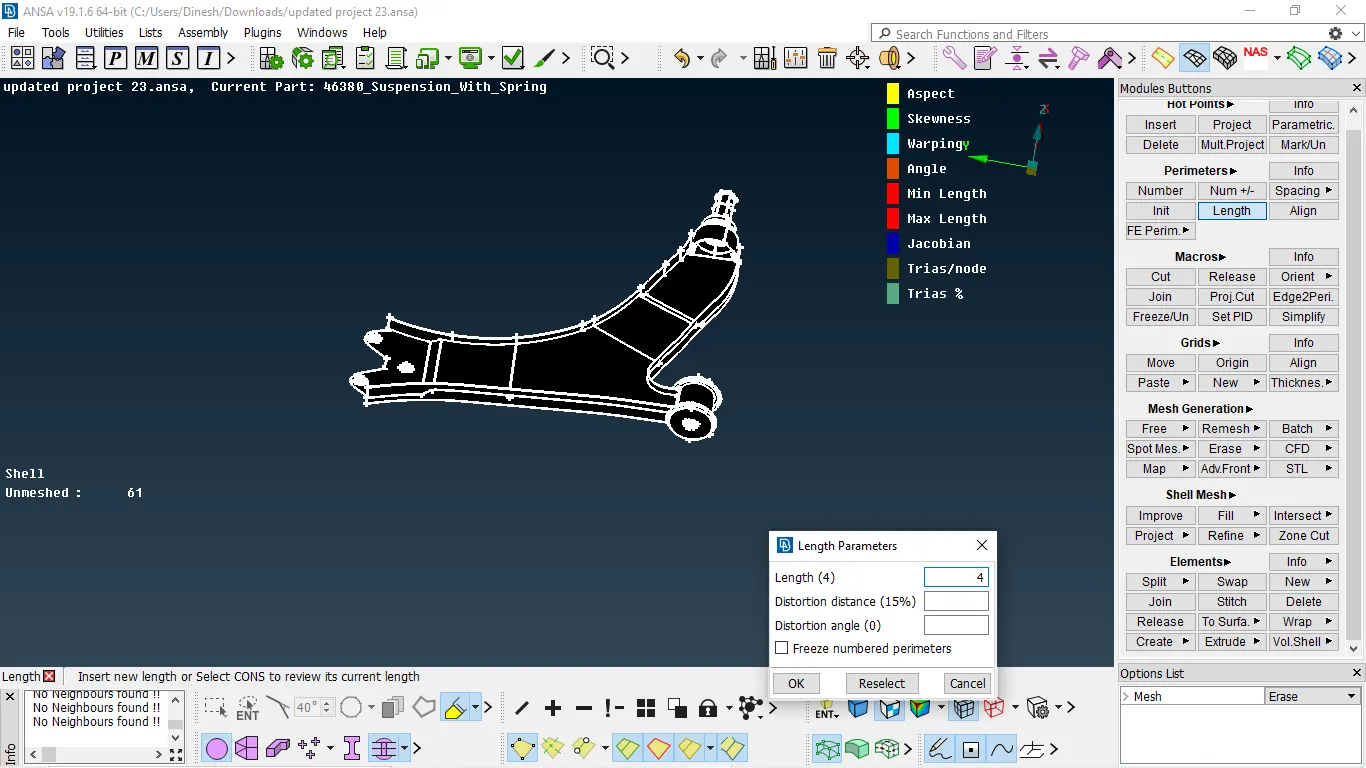
- For every part we need to mesh, the part which is less than 5mm thickness is taken mid surface for those part the parameters are like element type is mixed
- For other pard thickness greater than 5mm must mesh element type as tria or ortho tria
- Then after we need to select spot mesh and we need to select all features and mesh them by using ortho tria and other by trias
- Then after we need to select spot mesh and we need to select all features and mesh them by using ortho tria
- Reconstruction is done by using mesh reconstruct and smooth we can reduce the off elements
- BY using split and swap we can reduce the concentration of trias and decrease the stress concentration area
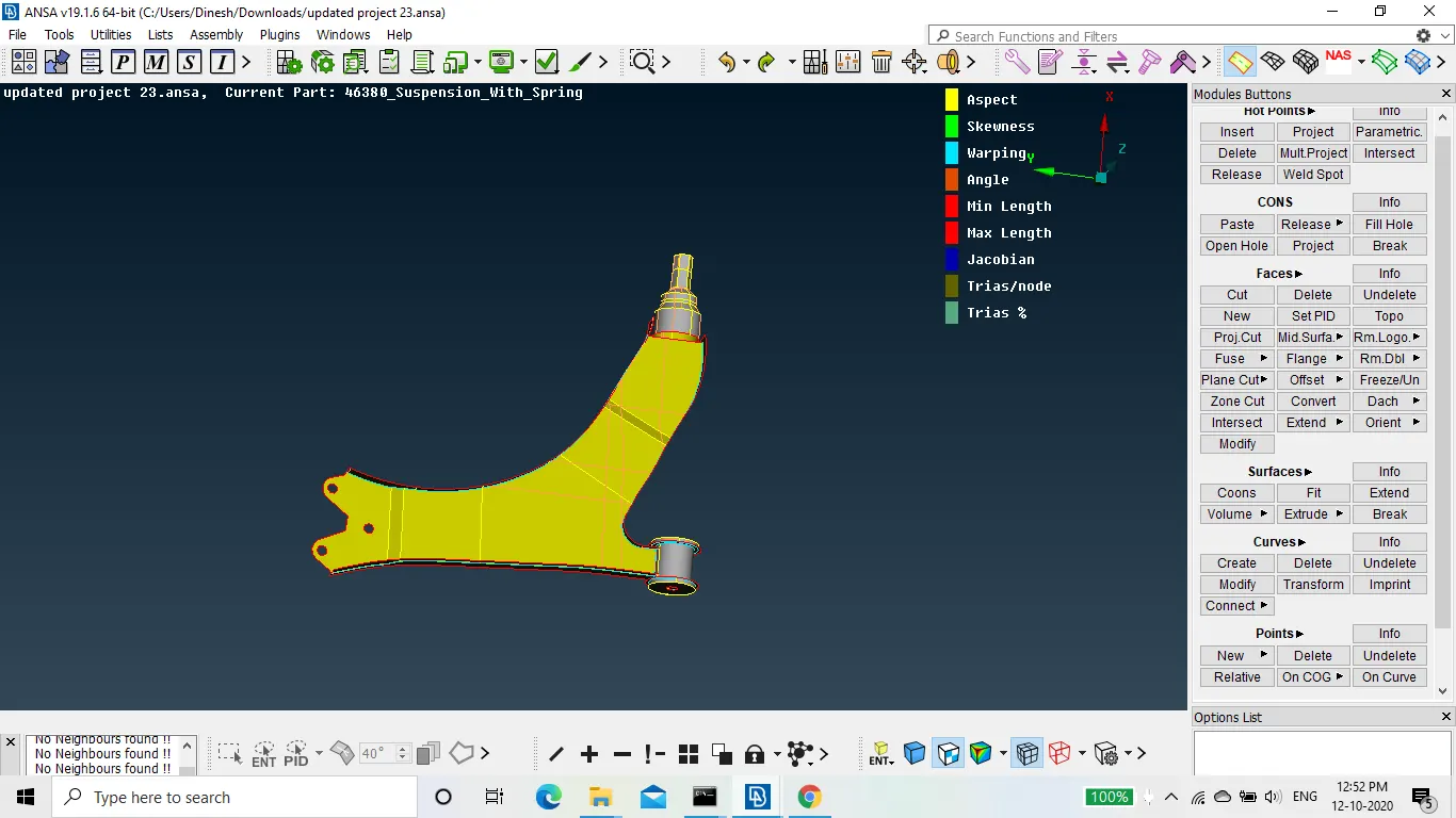
Fig 1:- component before meshing
- After completing we can start meshing, select the surface and start meshing
mesh generation → spot mesh → select surface and enter
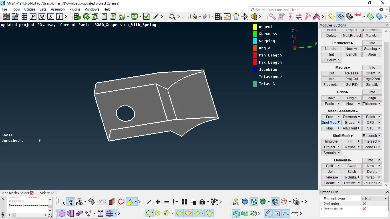
Fig 1:- performing meshing
- For better mesh than primary, we need to reconstruct
shell mesh → reconstruct → select the surface → enter
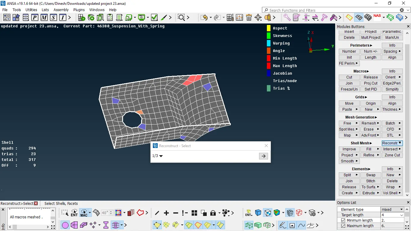
Fig 2:- performing reconstruction due high quality issues
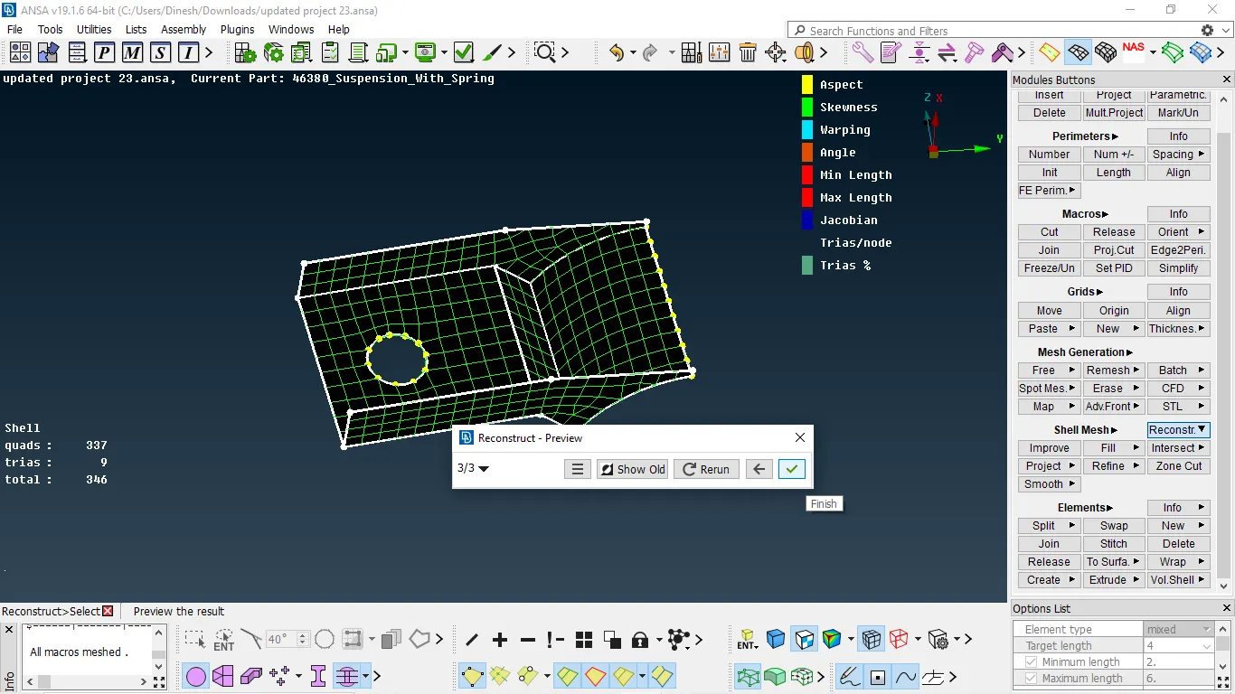
- To remove quality issues up to somewhat we use the smooth option
shell mesh → smooth → select the surface → enter
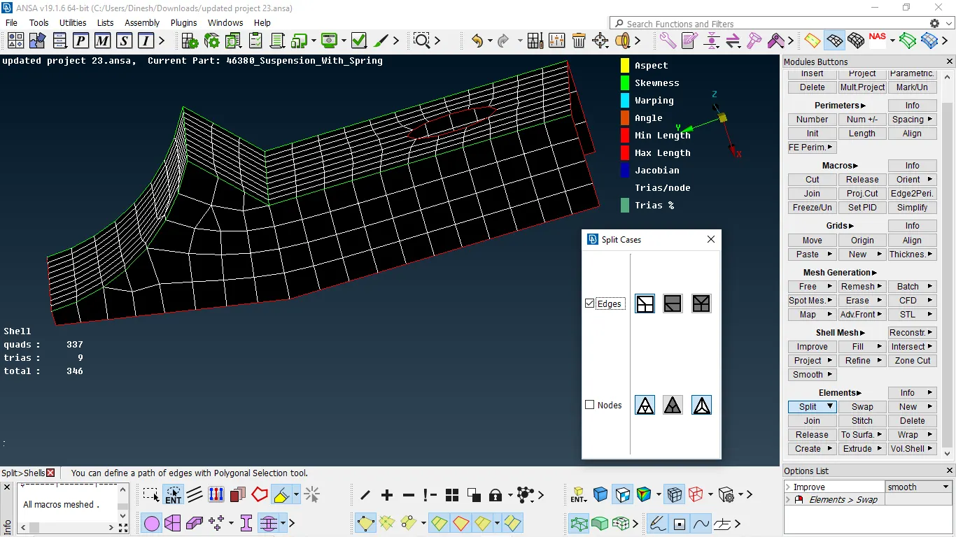
Fig 3:- mesh obtained after reconstruction and smooth
- After using these if any quality issue occurs we need to resolve it manually by spilt, swap, move
- Reducing trias using split and by the swap, we change the position of trias
elements → split → option → reconstruct
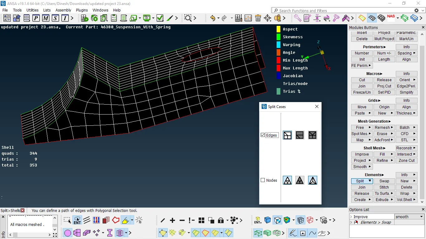
Fig 4:- after splitting trias
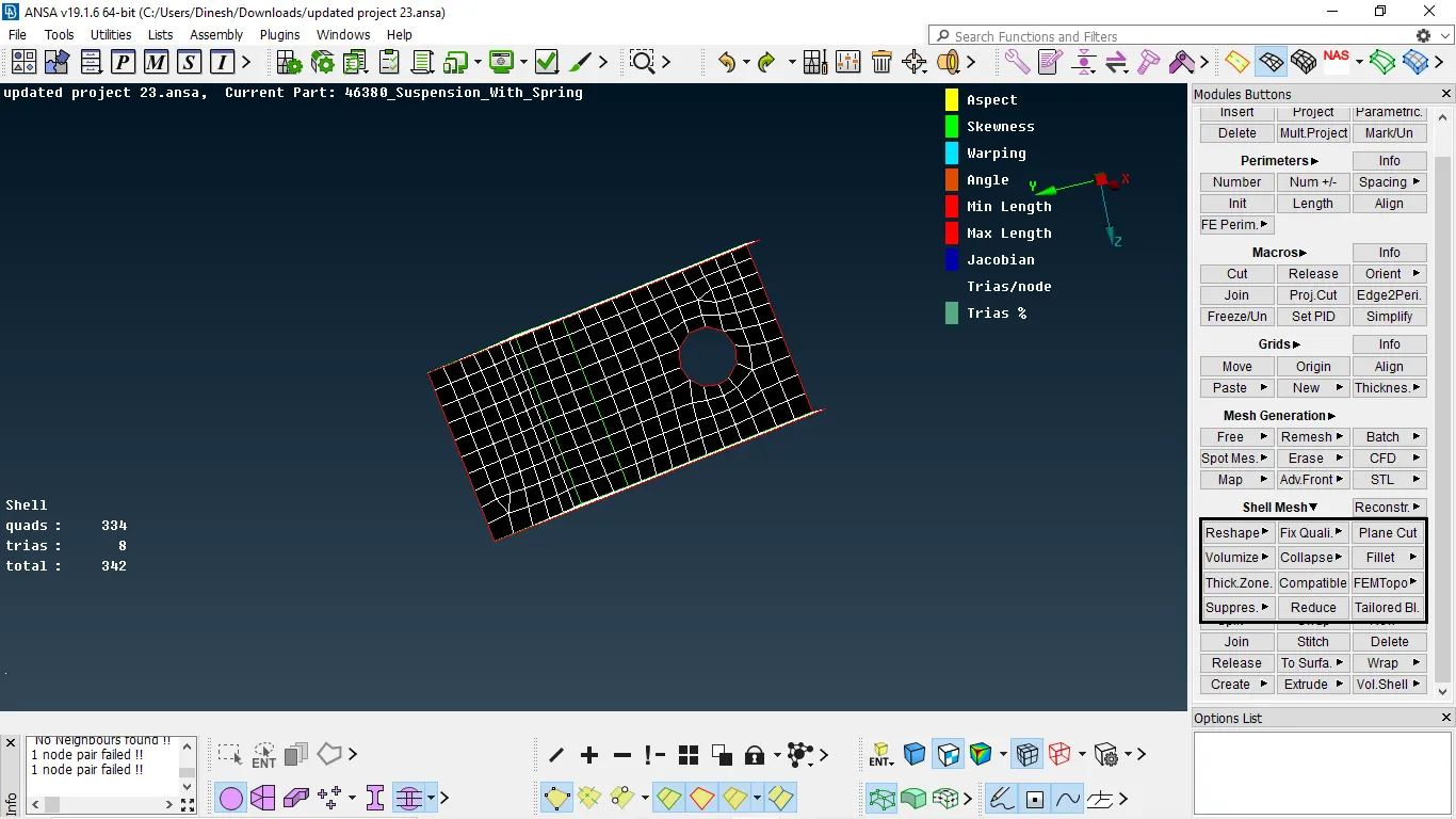
Fig 4:- component after meshing
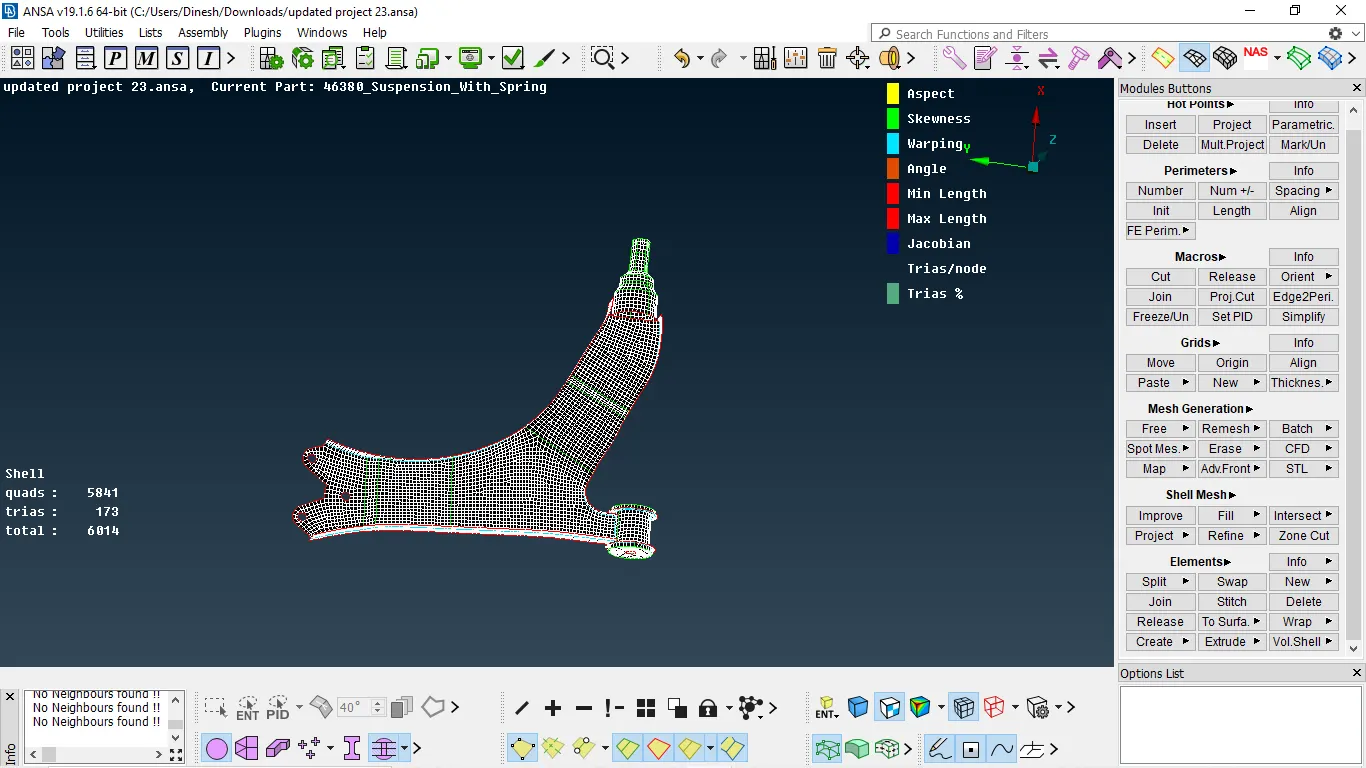
Fig 5:- component after meshing
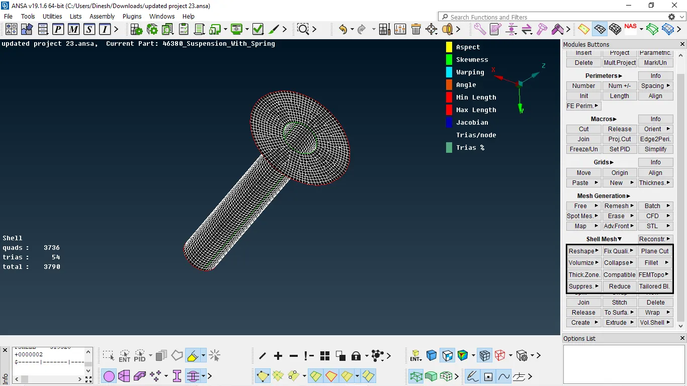
Fig 6:- component after meshing
VOLUME MESH:-
- Before performing volume mesh we need to perform shell mesh by parameters are tria/ortho trias.
- We no need to take mid surface for this mesh we directly mesh on the surface.
shell parameters → spot mesh → parameters as trias/ortho trias → select surface
- ortho trias will capture features and hole without kins and raised edges
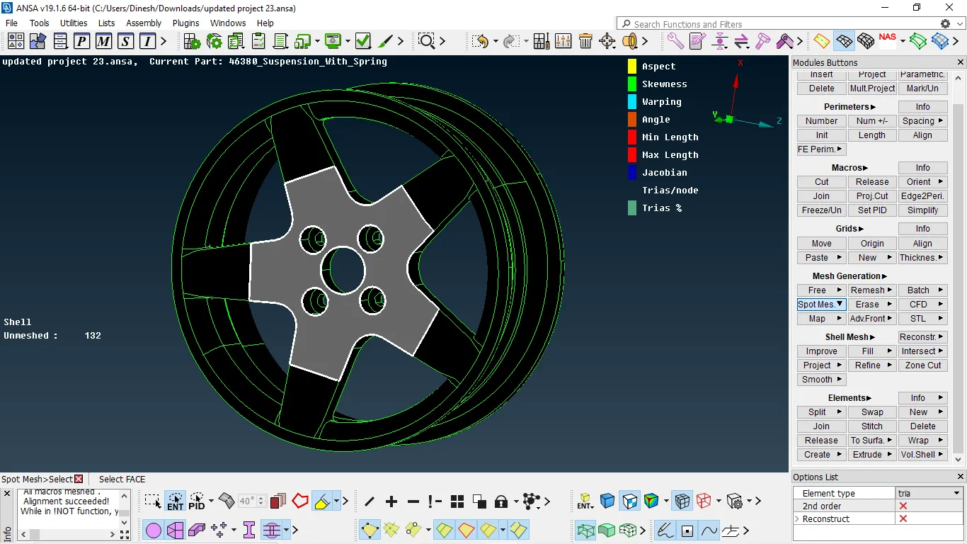
Fig 1:-surface selection to mesh
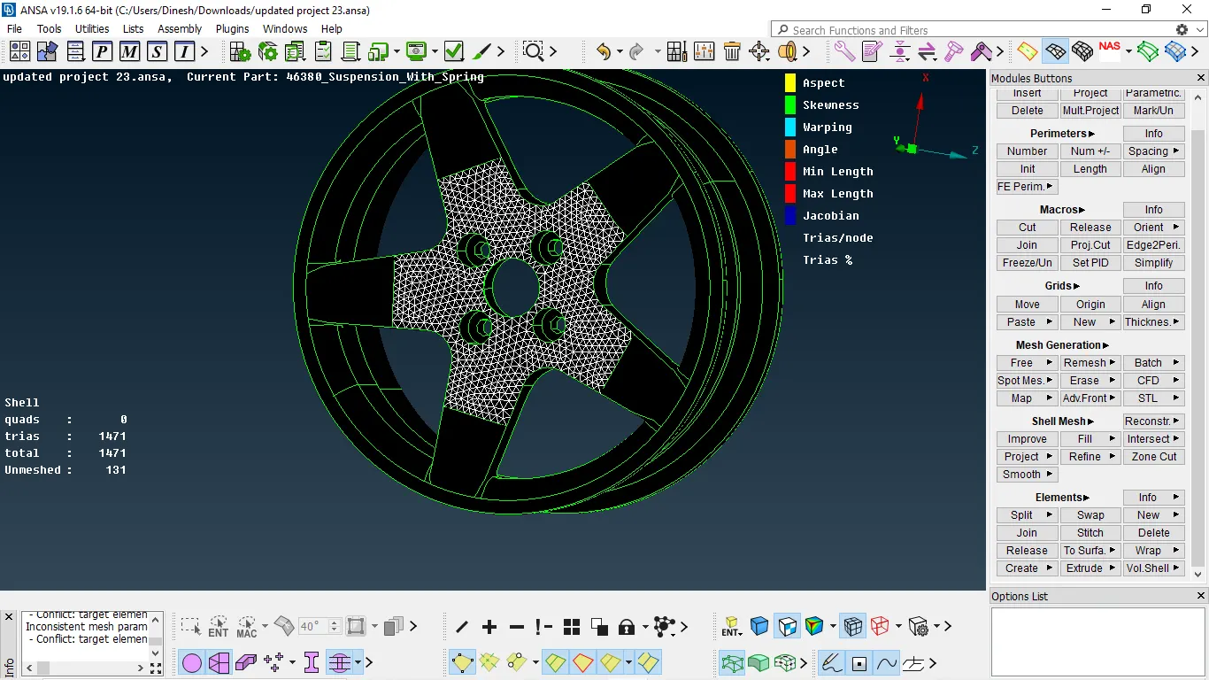
Fig 2:- mesh completed
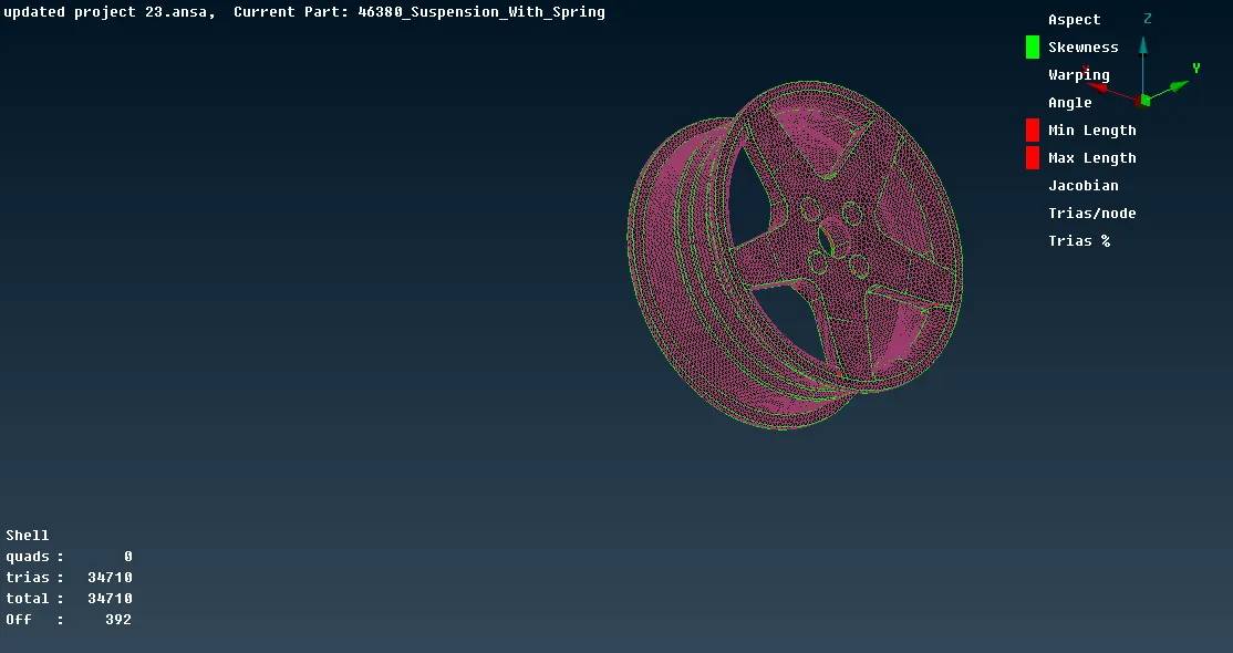
Fig 4:- mesh completed for the entire surface
- To perform volume mesh we need to define it and we need to add it to list
- Then we need to go to the list and right-click it then selects remesh and we can select tetra fem /tetra rapid
- After meshing we need to check the quality if any tetcollapse are present we need to eliminate them by manually or by using fix quality
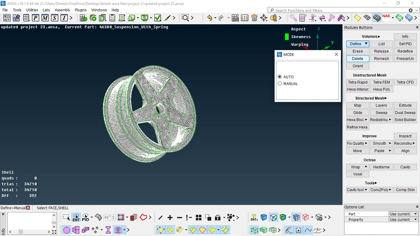
Fig 1:- define the component in the list
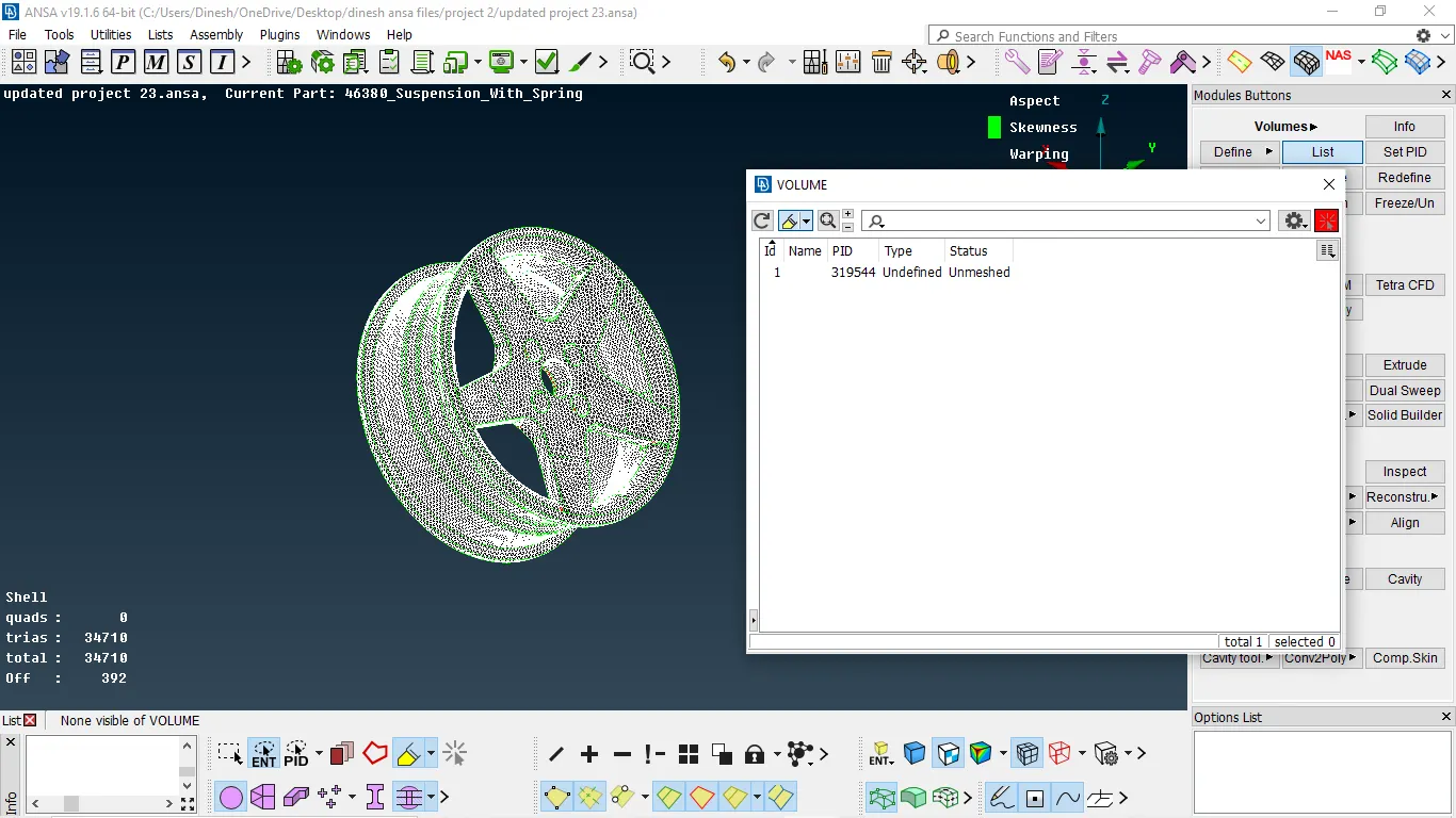
Fig 2:- component defined in the list
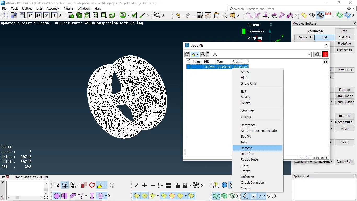
Fig 3:- performing volume mesh to the component
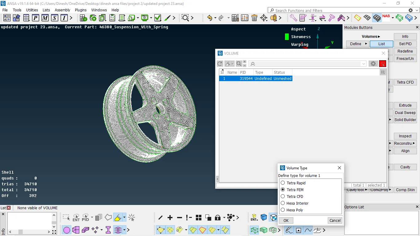
Fig 3:- selecting mesh type
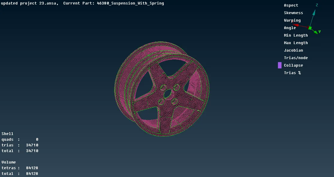
Fig 4:- mesh performed
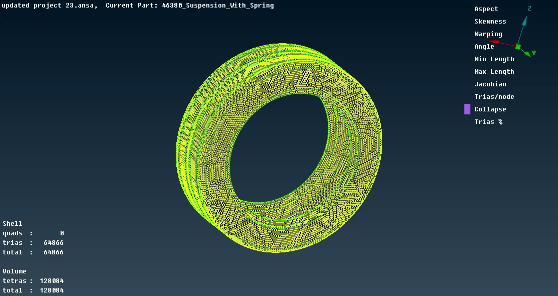
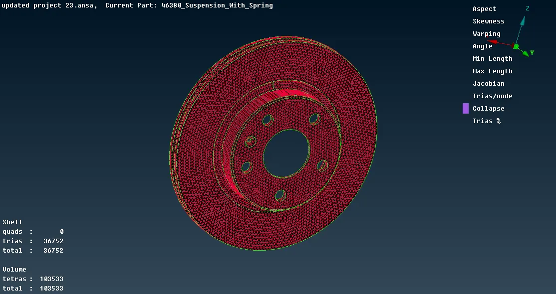
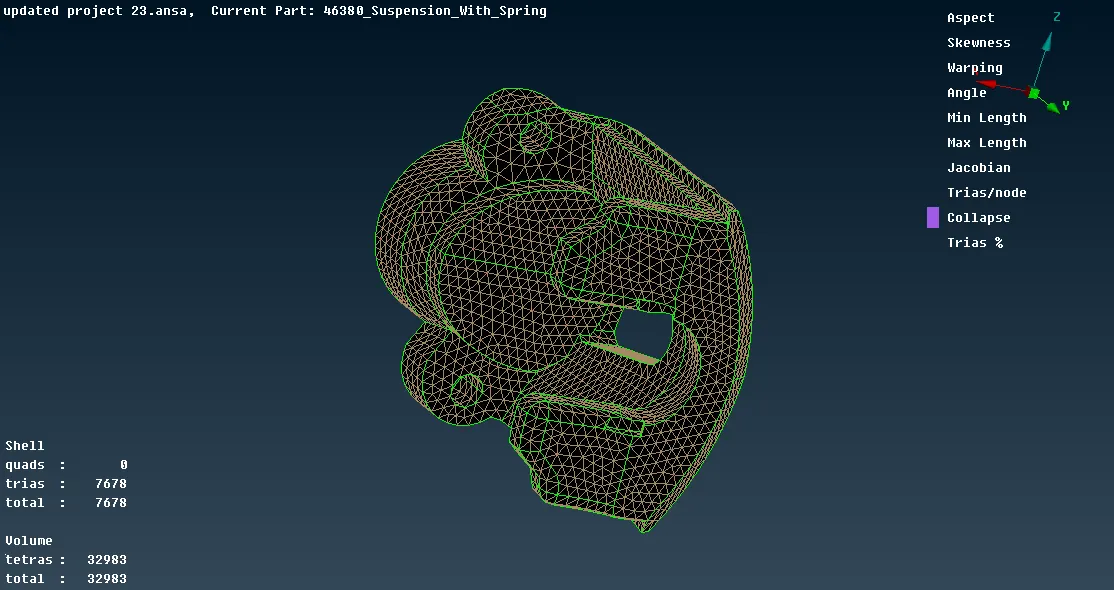
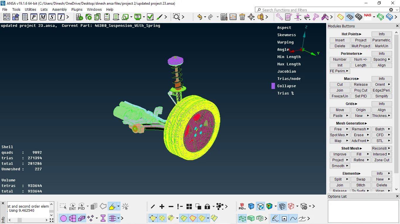
Fig 5:- volume mesh for entire surface
CONNECTIONS:
- As of first, we need to be spilt the component into different PID and arrange it properly.
- Then after we need checks the FE-model correctly and we must give appropriate connections to every component
TYPES OF CONNECTORS:-
- Depending upon the model there different types of connection some of them are many node RBE2, Two node RBE2, cluster RBE2, Weld connection.
MANY NODE RBE2:
It is connection majorly used for rigidizing the sub-assemblies of the part which having nut and bolt representation
procedure for creating RBE2
- First, we need to go to the Nastran deck then after select RBE2 in elements.
- After that, it will ask to select the nodes/elements by highlighting the nodes or elements option
- Then after selecting nodes press enter after that set it into a group and press enter such that RBE2 connection is made
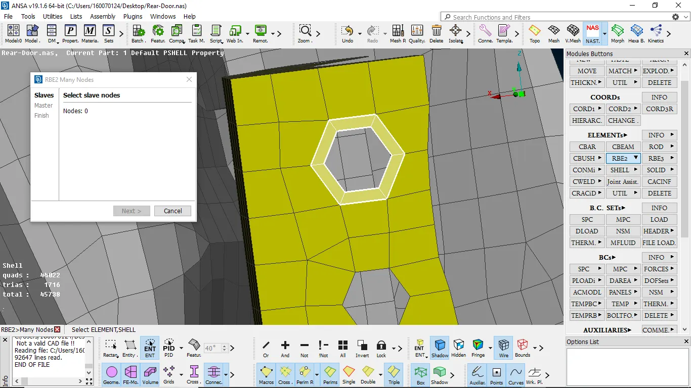
fig:-1 selecting elements
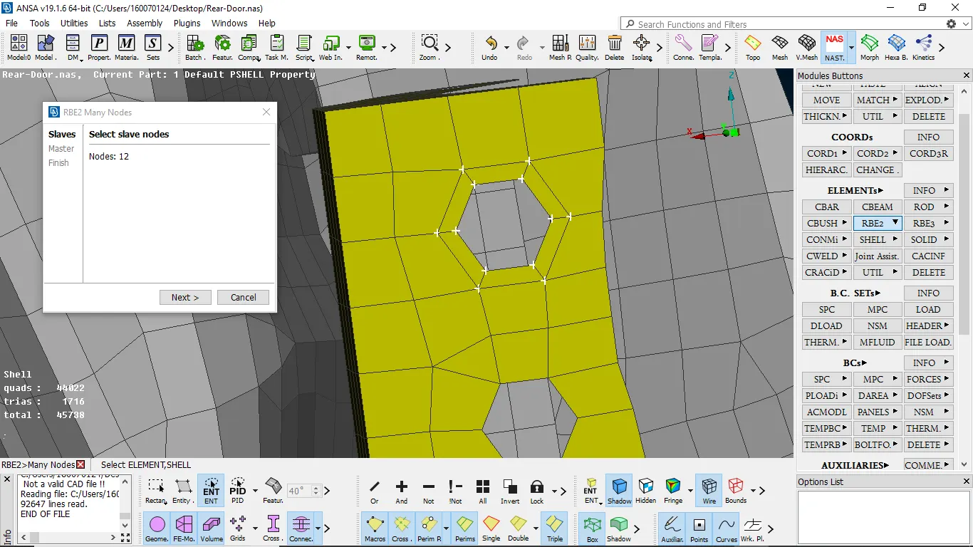
fig:-2 slave are selected
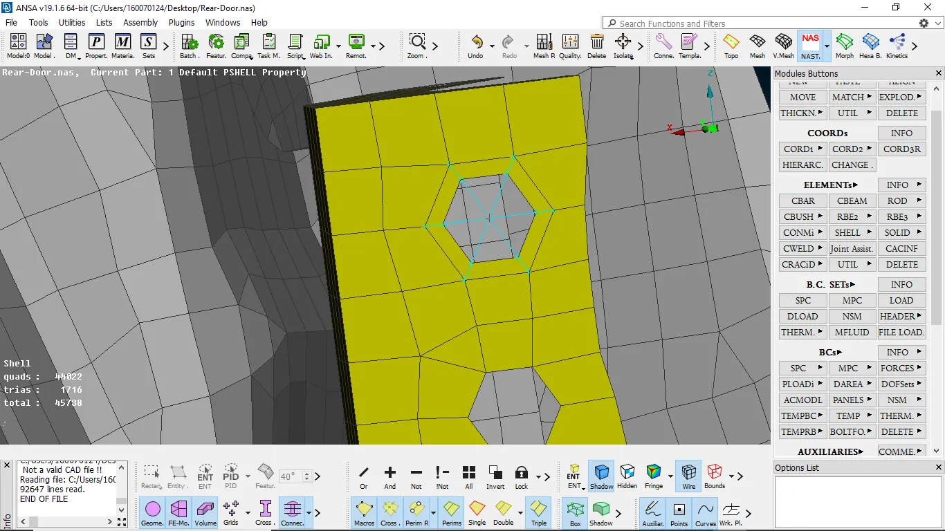
fig-3 RB2 connection obtained
TWO NODE RBE2:-
It is majorly is used to connect nut and bolt in assembly. It is going to connect two RBE2 connection by the stem, and also used to connect two subcomponent
procedure for creating two-node RBE2
- we make RBE2 Connection to the assembly that has nut and bolt contact
- Then we need to select RBE2 two-node and then we need to select the master node of both the top face and bottom face
- Press enter node is created, in this we constrain DOF
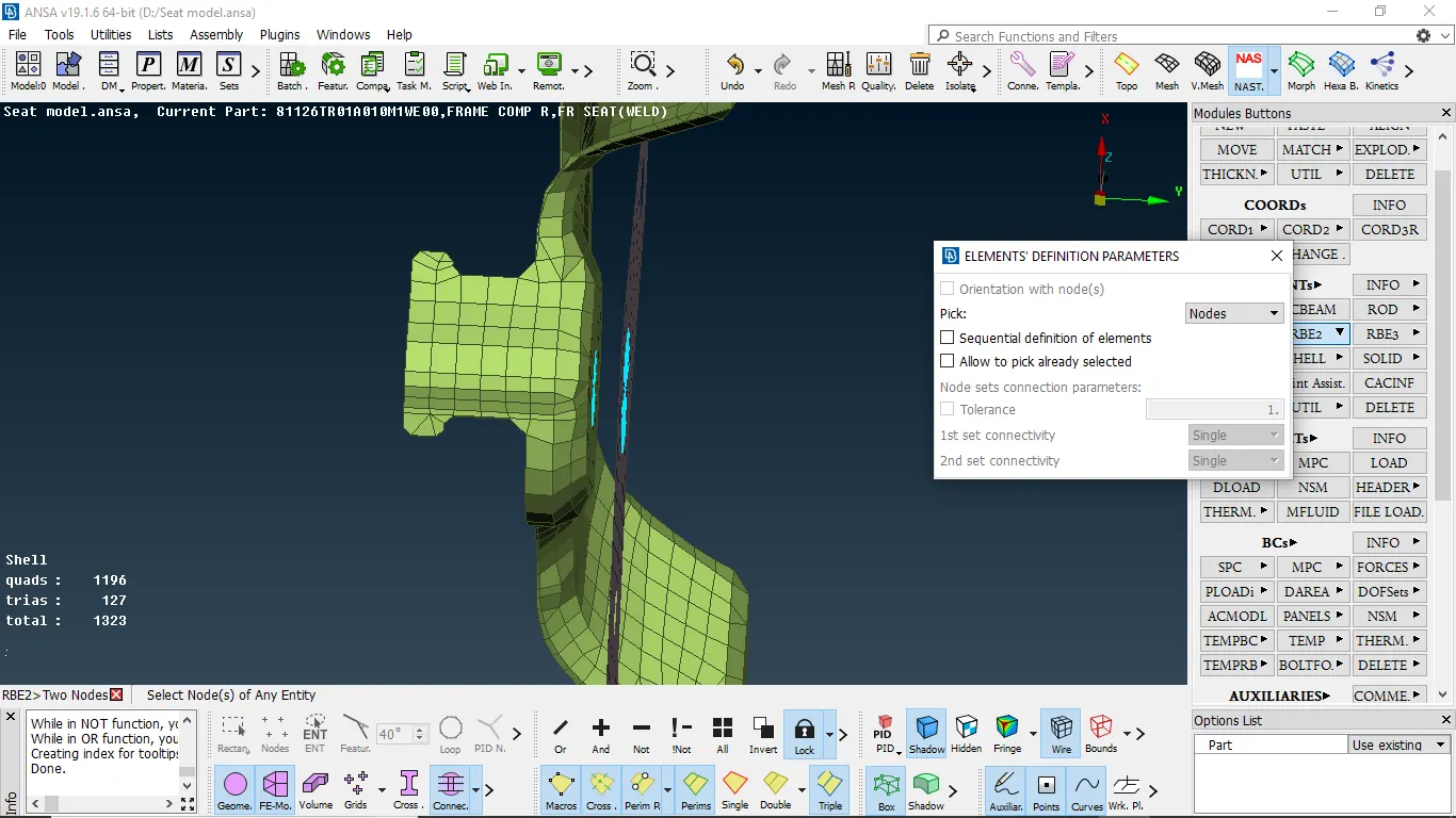
fig 1:- selecting components
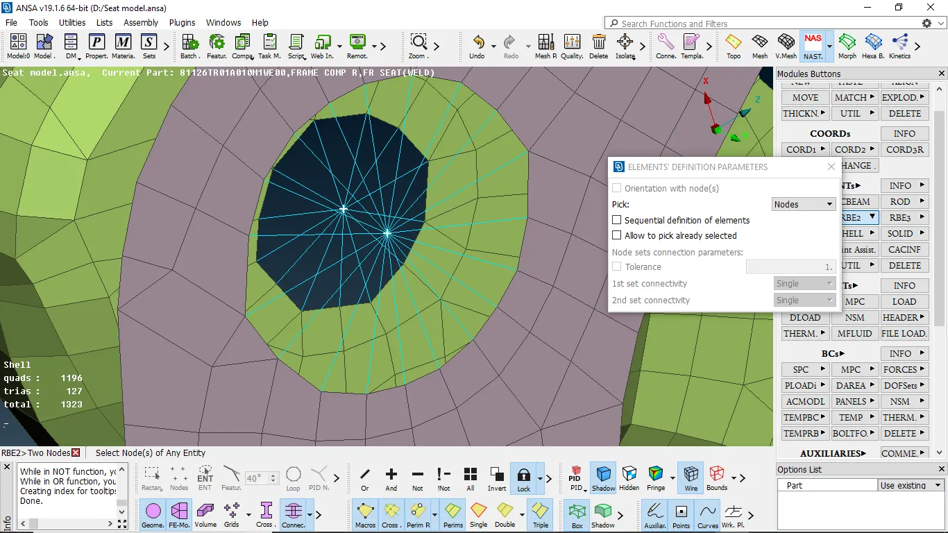
fig 2:-node are being selected
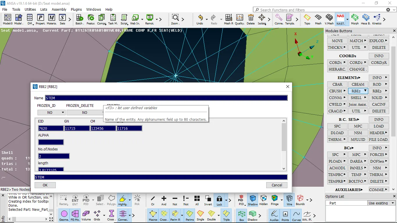
fig 3:- creating PID
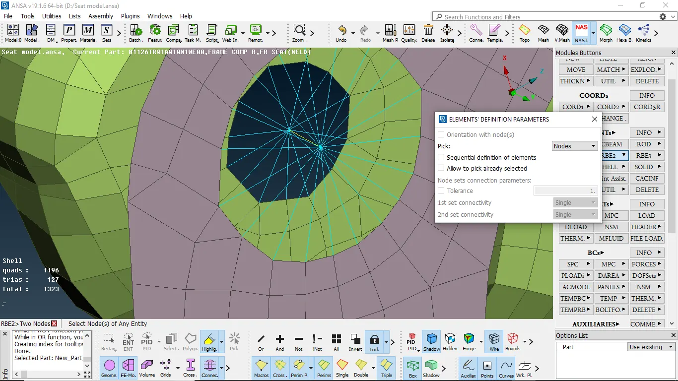
fig 4:-two-node rbe2 connection obtained
CLUSTER RBE2
It is used to connect two sub-assembly which has motion and make to be constrained
Procedure :
- select the two sub-assemblies by many node RBE2 and then select the node of the surface at a time and press enter
- such that cluster RBE2 is created
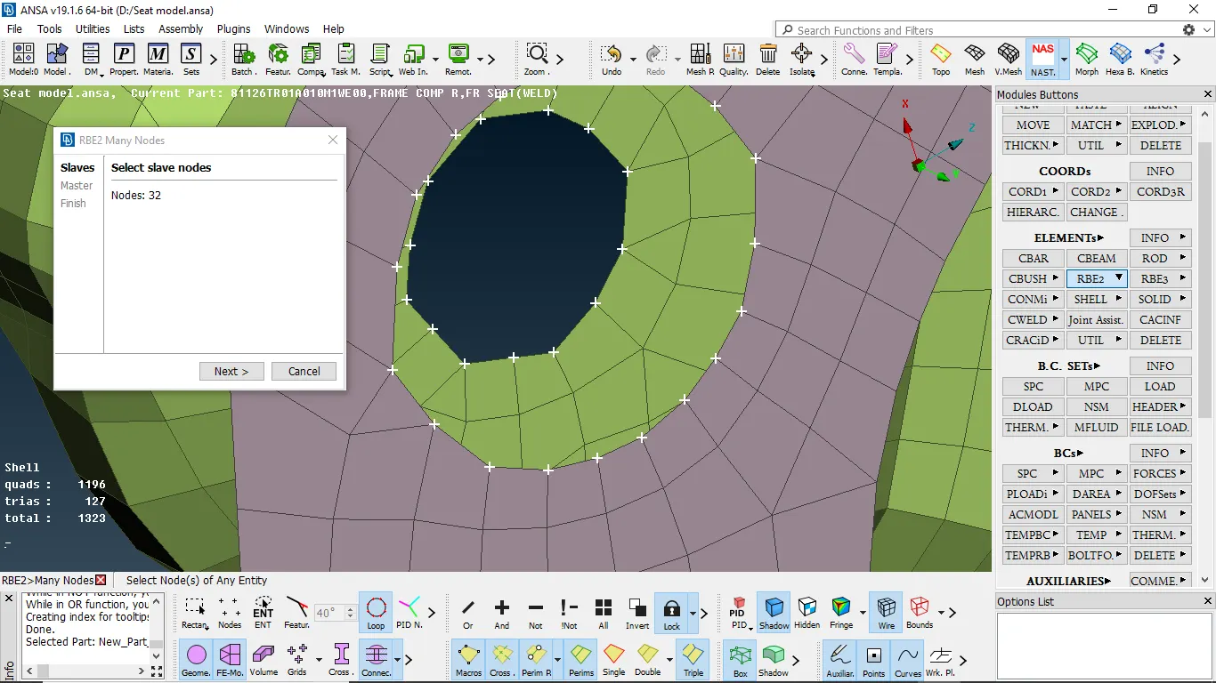
fig 1:- selecting nodes of two components
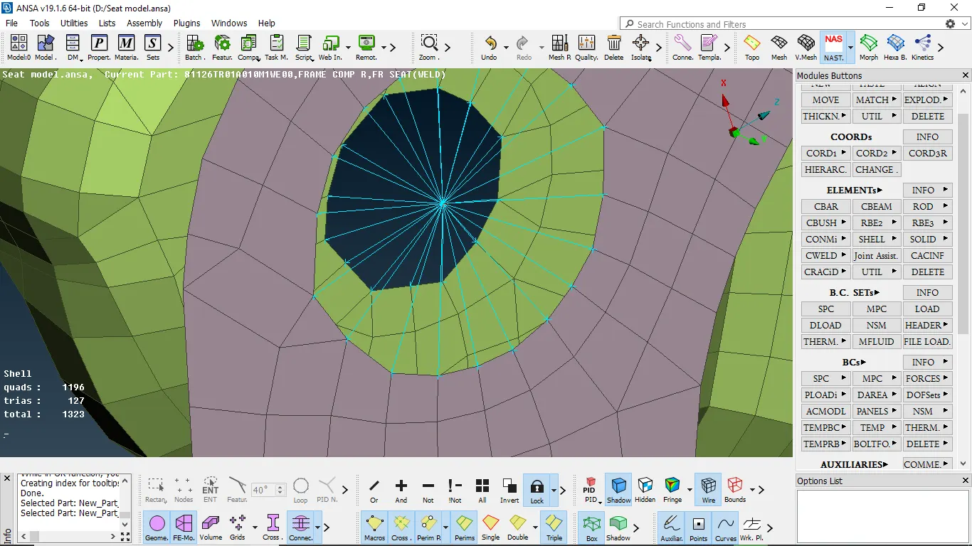
fig 2:- RBE2 cluster has been obtained
WELD CONNECTION:
we create a weld connection between two components to give o rigid connection where it is required
procedure:
- we need to create a curve by using a feature2 curve in the mesh module if is an FE element
- Then after we need to convert the curve into the seam line
- Then by using connection we should select the line and we need to select the components to be welded by pressing F1 and then select overlap shell/ y joint shell
- mention the search distance and we need to mention width and step length as target element length and create a weld PID by pressing shift+? and apply
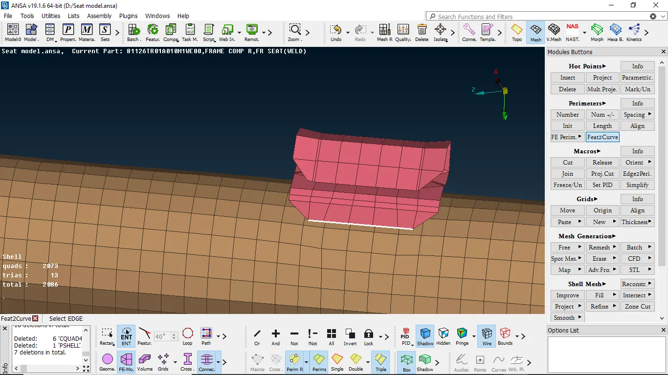
fig 1:- forming a curve to represent weld connections
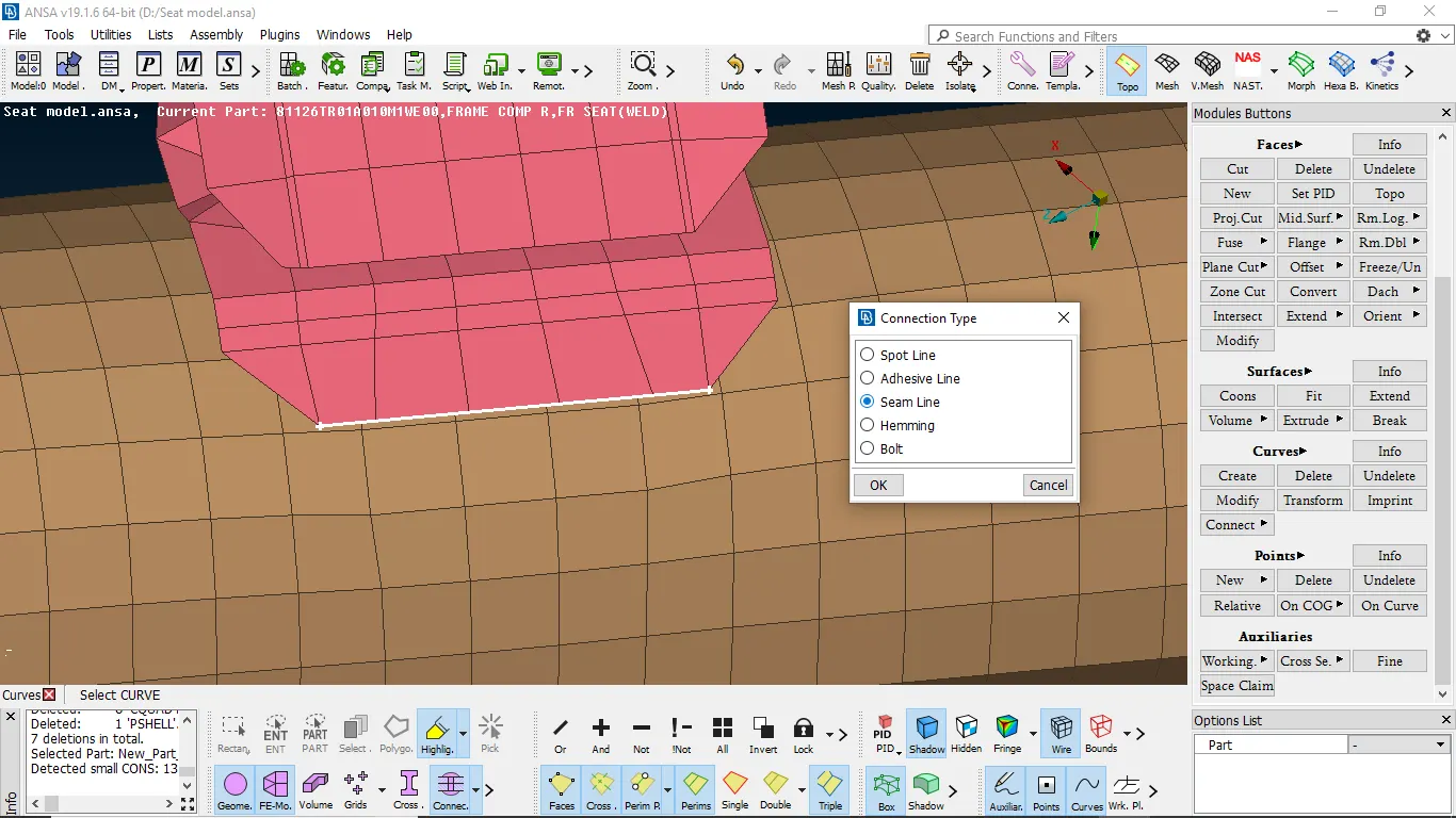
fig 2:- converting curve to connection
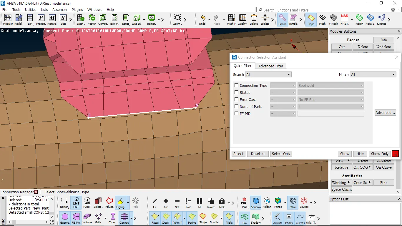
fig 3:- deploying property for weld
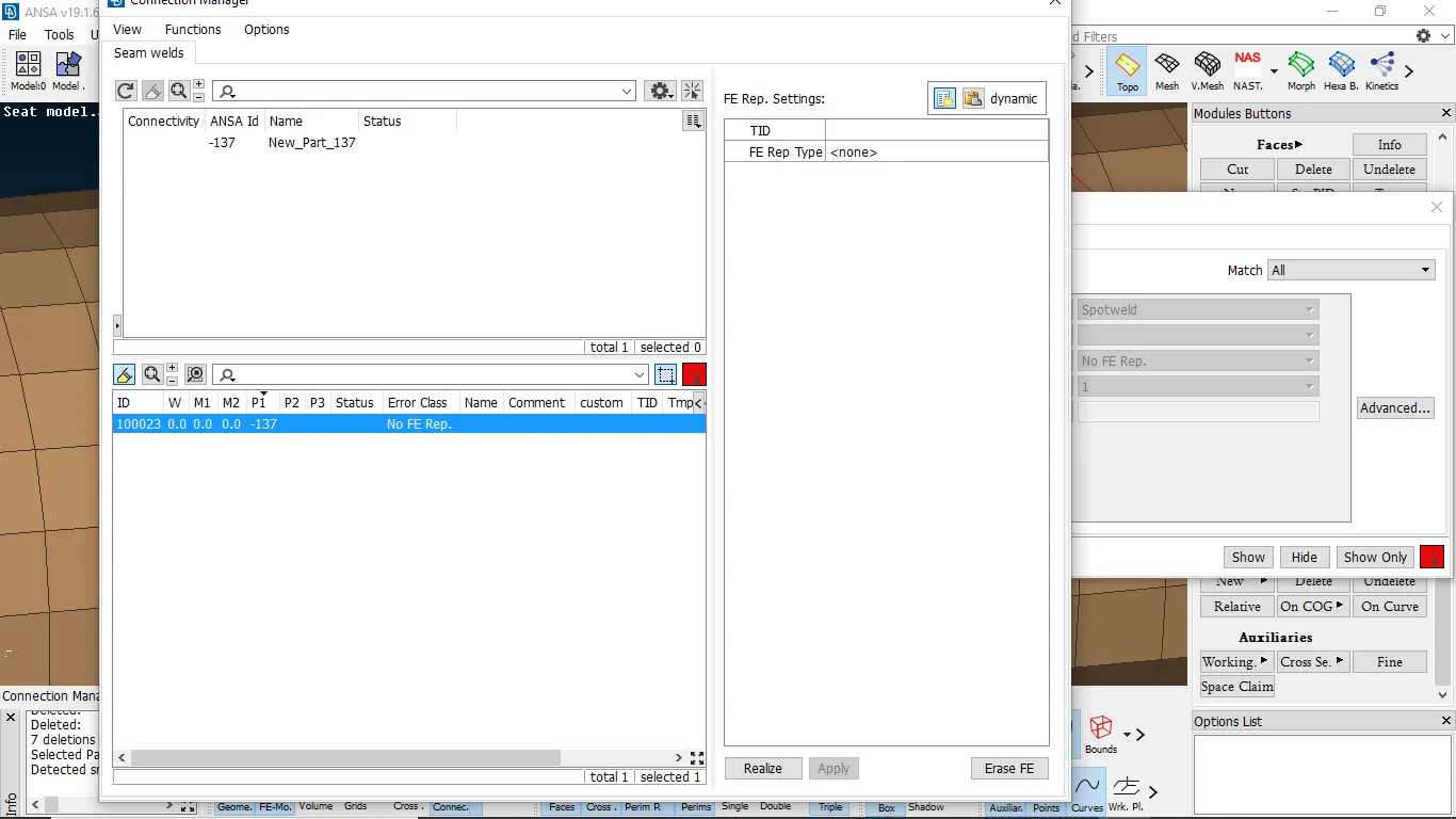
fig 4:- select weld type
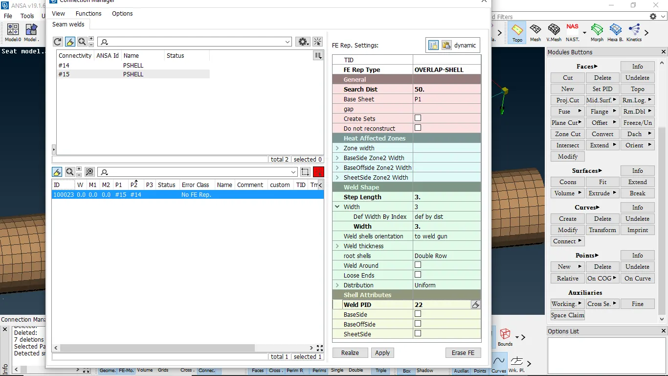
fig 5:- Assigning property for weld
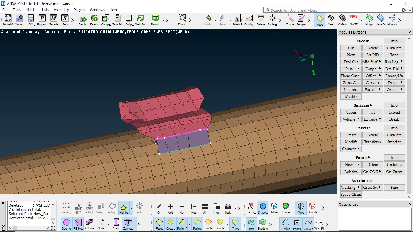
Deploying connection to the suspension system
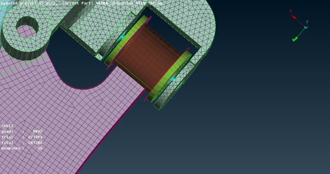
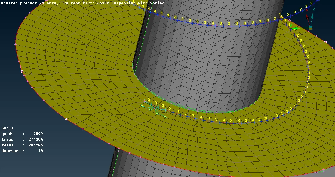
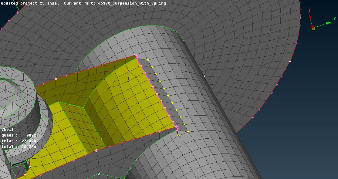
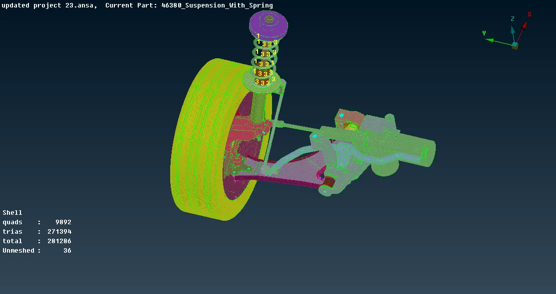
- component given both connection are
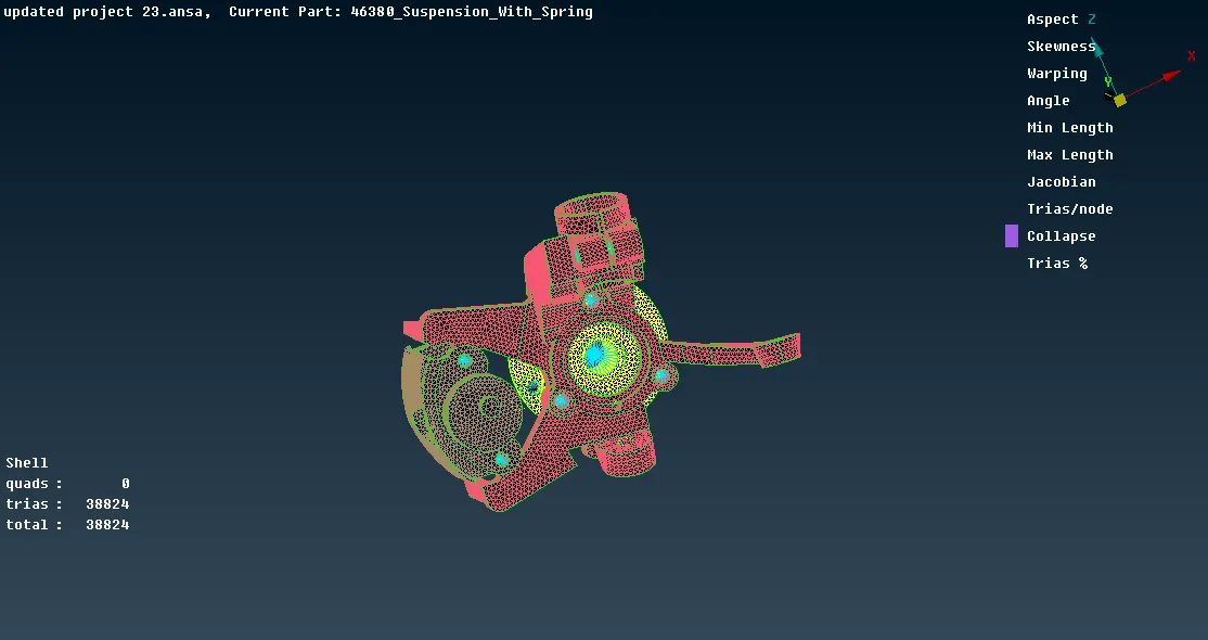
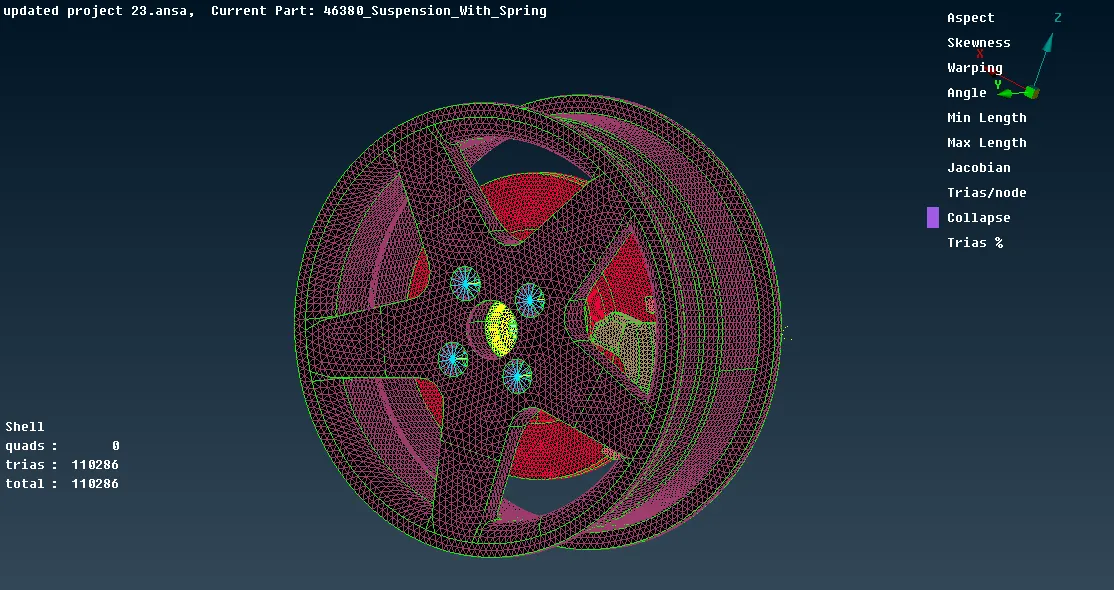
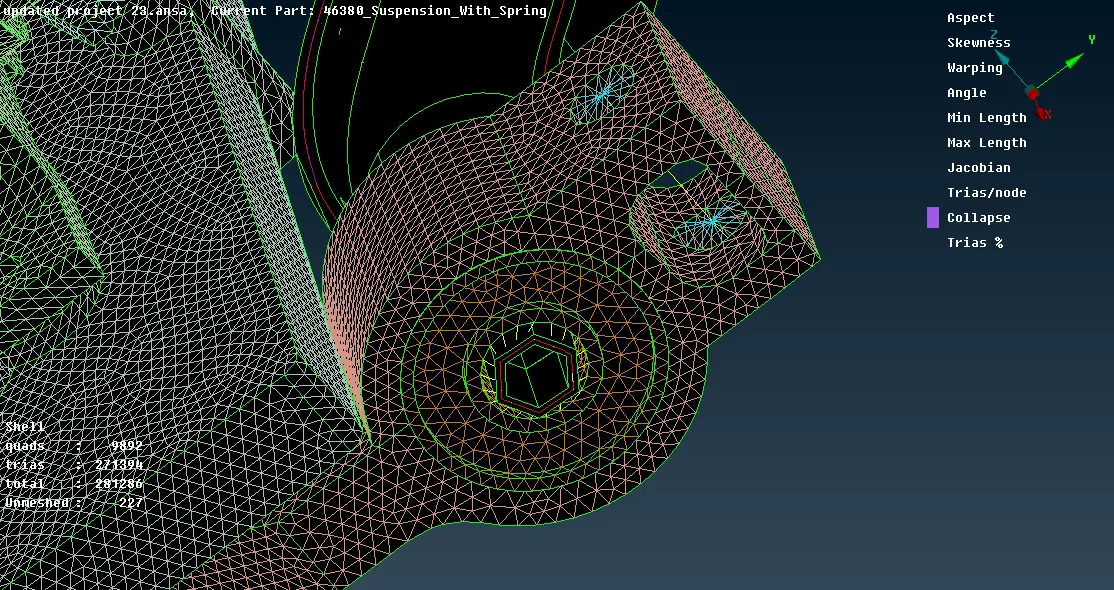
Two node Rbe 2 connections
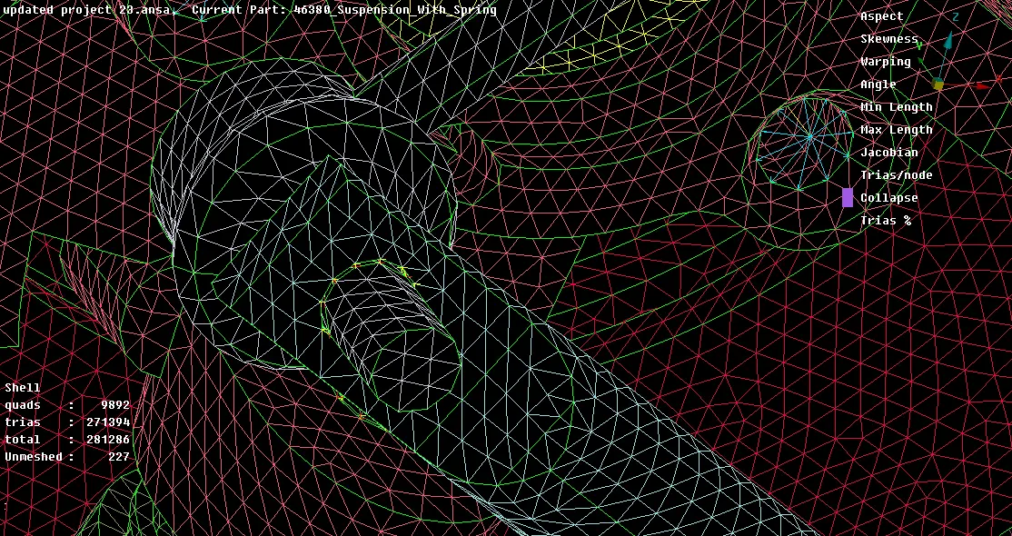
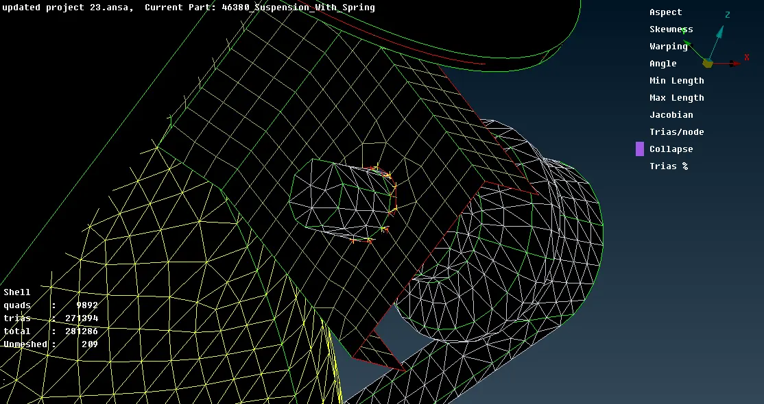
RBE 2 CLUSTER CONNECTIONS
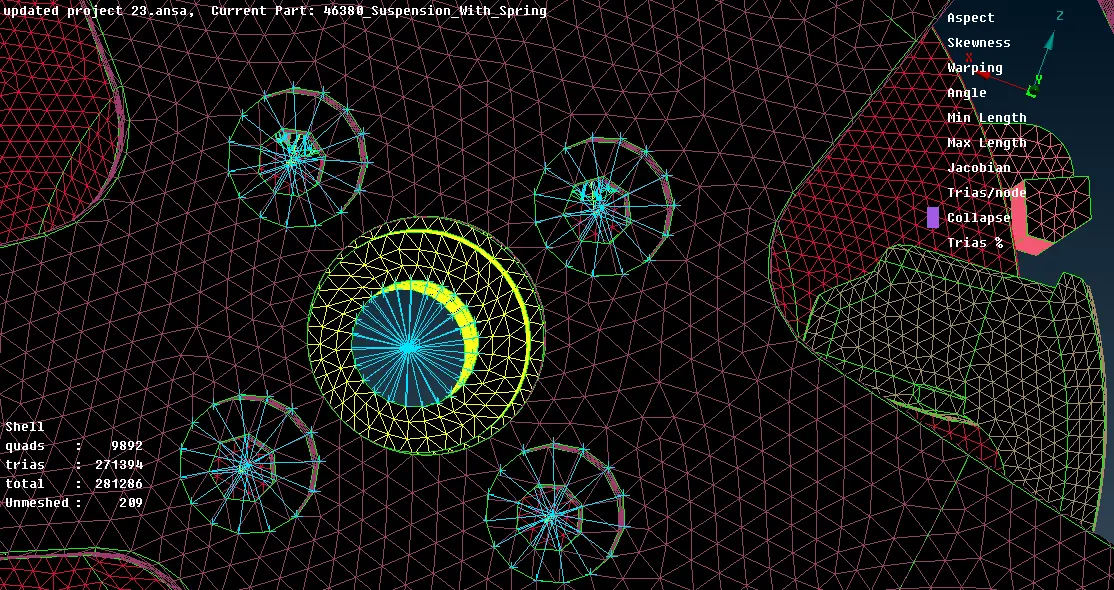
WELD CONNECTION
ALL CONNECTIONS
CONCLUSION
- Understood how to extract the mid surface at complex areas
- understood how to mesh large component
- understood how to reduce the quality error in mesh
- understood the extension and attachment of the mount to parent surface
- understood how to capture feature by satisfying quality criteria
- understood how to perform divide faces to defeature the fillet area
- learned how to perform volume mesh
- learned how to capture fillet area properly
- learned the difference between structured and unstructured mesh
- learned how to resolve tetcollapse issues
- learned to deploy connection to attach subsystem
- Gained knowledge to make the connection with respective connectors