Project 2
Aim : Route the wiring harness on given car body and prepare flatten view drawing in CATIA V5.
Objective : The objective is to route the wiring harness and prepare flatten drawing view for the tailgate of the car applying all packaging rules and industry best practices. Apply protection coverings and consider the clearance requirements, clipping/clamping selection, harness fixing requirements, harness continuity to design the wiring harness.
The back door harness consists of two harness routing, one for tail lamps and another for number plate lighting. Hence the tail lamp harness consists of an interconnection connector and two connectors for tail lamp, and the number plate lighting harness consists of an interconnecction connector and two connectors for number plate lightings. The furr tree clips are used in between to provide positive clamping for the routed harness.
Totally the tail gate wiring harness consists of 8 pole connectors for innterconnection connectors, 2 pole connectors for tail lamp connectors and number plate lamp connectors, few furr tree clips for mountings and protection tubes for harness wiring protection.
Assumptions and packaging rules :
- Wiring harness routing shall provide ease in manufacturing, accessibility, easy removal and easy maintenance of attached equioments and routing harness.
- Wiring harness should be routed in such a way that it is easy to assemble on a vehicle.
- Wiring harness should be kept away from sharp environments like sheet metal brackets, panel edges, corners etc.
- Avoid harness routing and clipping in blind zone of operator during harness installation.
- Ensure that routing meets the clearance requirements with the different surrounding parts.
- Routing shall provide enough slack for each branch to avoid additional stress on wire and terminal crimping joints but ensure that extra slack does not caause wiring harness foul with surrounding parts and impact desired clearance requirements.
- Enough clamps should be provided to ensure the positive clearnace with surrounding parts and imapct desired clearance requirements.
- Enough clamps should be provided to ensure the positive clearance with surrounding and safety of wiring harness.
- Use of plastic guided channels are recommended to meet the clearance in critical areas if it is difficult to achieve by use of clamps.
- Branch length should be minimum 50 mm.
- Minimum distance between clip and nearest branching point should be minimum 50 mm.
- Minimum distance between two breakouts should be 50mm.
- Limit the no. of branchjes from single branch point to 4.
- Ensure that harness protection is provided according to surrounding temperature, manufacturibilty and expected reliabilty.
- The min. bend radius is to be 1.4.
- Consider min. 5% slack in the wiring harness if needed.
Procedure:
Step 1. Create context assembly product file
As shown below the tail gate harness mainly consists of Tail gate assembly containing 3D CAD assembly of tail gate , tail lamp geometrical bundle for tail lamp harness routing and number plate geometrical bundle for number plate lamp harness routing. The tail lamp geometrical bundle and number plate lamp geometrical bundle are saved in two seperate folders in the main context assembly folder.
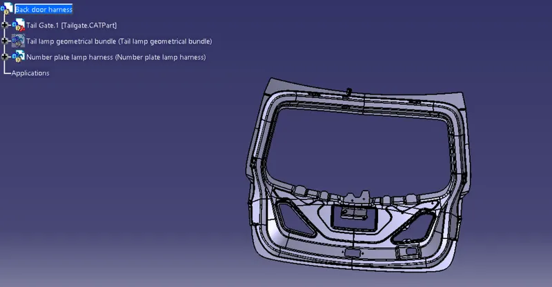
Image : Context assembly product file
Step 2. Defining the connectors electrically
- Before adding connectors into the geometrical bundle product file the connectors are to be defined electrically.
- Create required geometrical parameters like bundle connection point, connector connection axis and cavity connection axis in the part design workbench as shown in the image below.
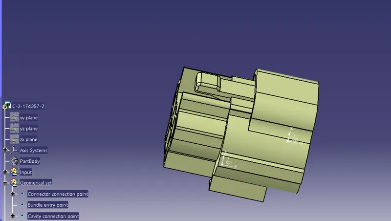
Image : Defining geometrical parameters
- Define connector with electrical parameters such as connector connection point, bundle connection point and cavity connection point.
- Defining connector connection point using connector connection point command and define the parameters as shown in the image below.
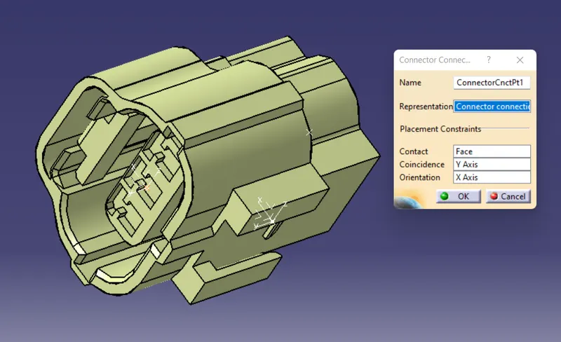
Image : Defining connector connection point
- Define bundle connection point using bundle connection point command and define the parameters as below.
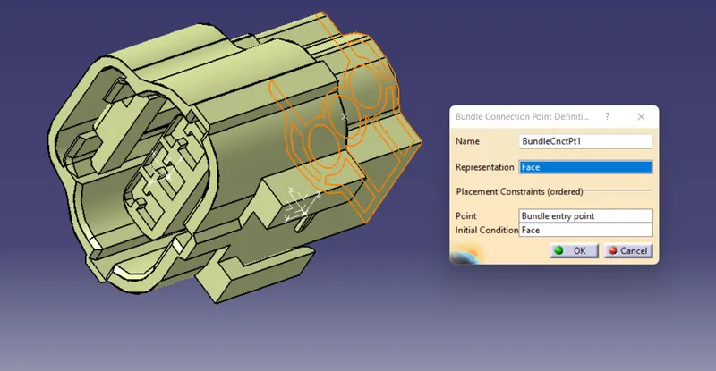
Image : Defining bundle connection point
- Define cavity connection point using cavity connection point command and defining the parameters as shown below.
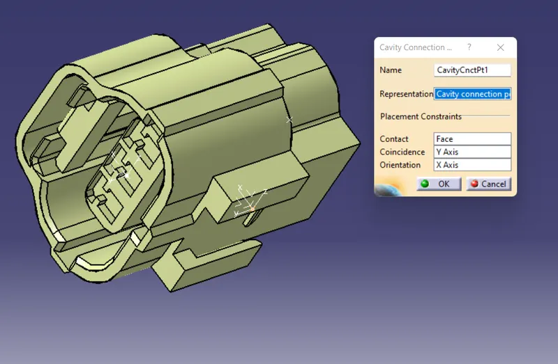
Image : Defining cavity connection point
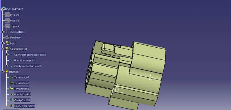
Hence the connector is defined electrically.
Step 3. Defining furr tree clips as supports
- Create geometrical parameters such as entry point, entry plane, exit point, exit plane in the part design workbench as shown in the image below.
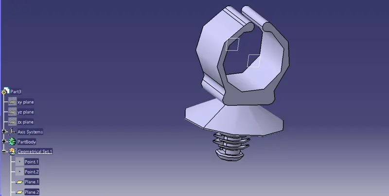
Image : Creating geometrical parameters
- Go to electrical part design workbench, select define support command and define the parameters as per the requirements shown below. A support is defined twice where the entry and exit planes are defined from both of the created planes so that the entry is possible from both the sides of the furr tree clips for the wires.
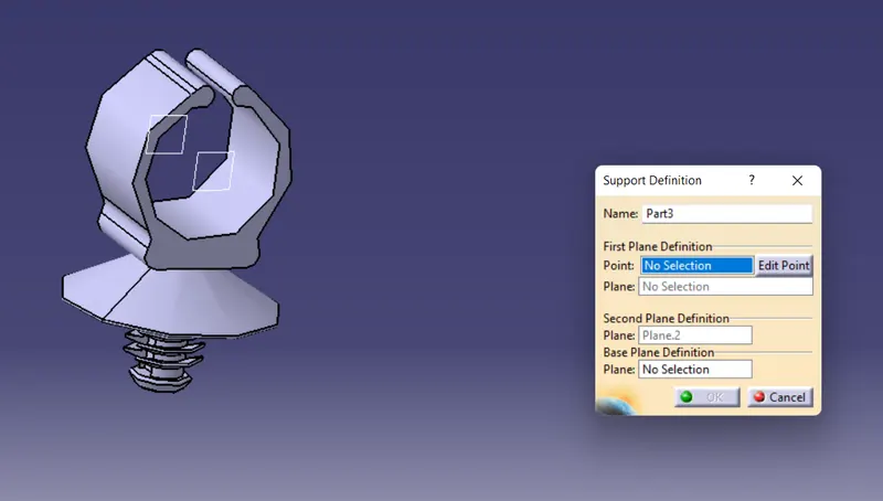
Image : Define furr tree clip as support.
Step 4. Inserting connectors into their respective geometrical bundle one by one and positioning them
- For tail lamp harness the interconnection connector is positioned in the top portion of the tail gate and the other two connectors are positioned where the tail lamps are actually going to be situated in its respective geometrical bundle as shown in the image below.
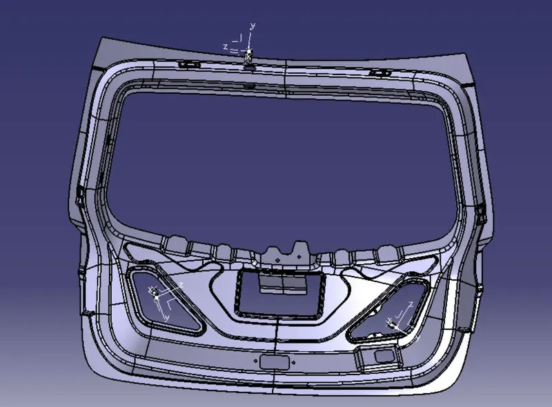
Image : Positioning connectors for tail lamp harness
- For number plate lamp harness the interconnection connector is positioned in the top portion of the tail gate and the other two connectors are positioned where the number plate lamps are actually going to be situated in its respective geometrical bundle as shown in the image below.
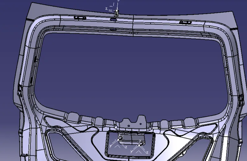
Image : Positioning connectors for number plate lamp harness
Step 5. Positioning furr tree clips for positive clamping
The furr tree clips are positioned for both the tail lamp harness and number plate lamp harness into their respective geometrical bundles as shown below. Fir tree clips ensure proper routing through the tail gate.
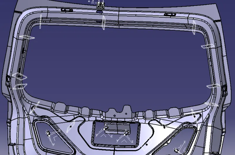
Image : Positioning furr tree clips for positive clamping
Step 7. Routing the wiring harness
- routing.
- First the tail lamp harness routed individually into the tail lamp geometrical bundle.
- Go to electrical harness assembly workbench and select geometrical bundle command and select the geometrical bundle in the model tree. Then select the multibranchable command to start the bundle routing and go to route definition inside the branch definition.
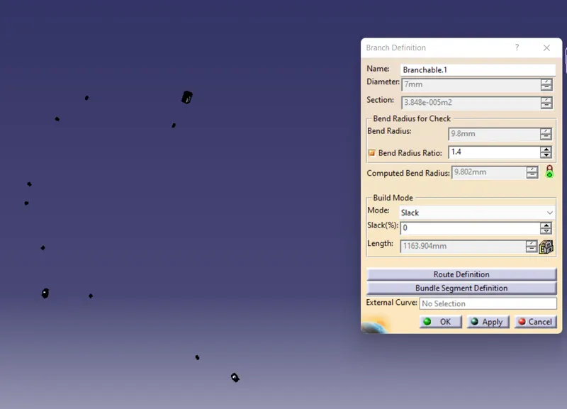
Image : Defining main branch
- The bundle routing starts from interconnection connector and then to the fir tree clips which are added into the route definition one after another for connectivity and finally to the tail lamp connector as shown in the images below.
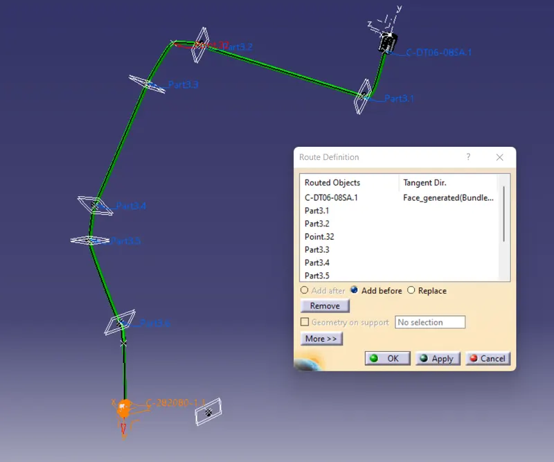
Image : Routing harness from interconnection connector to tail lamp connector.
- Adding branching points wherever necessary using add branch point command as shown below
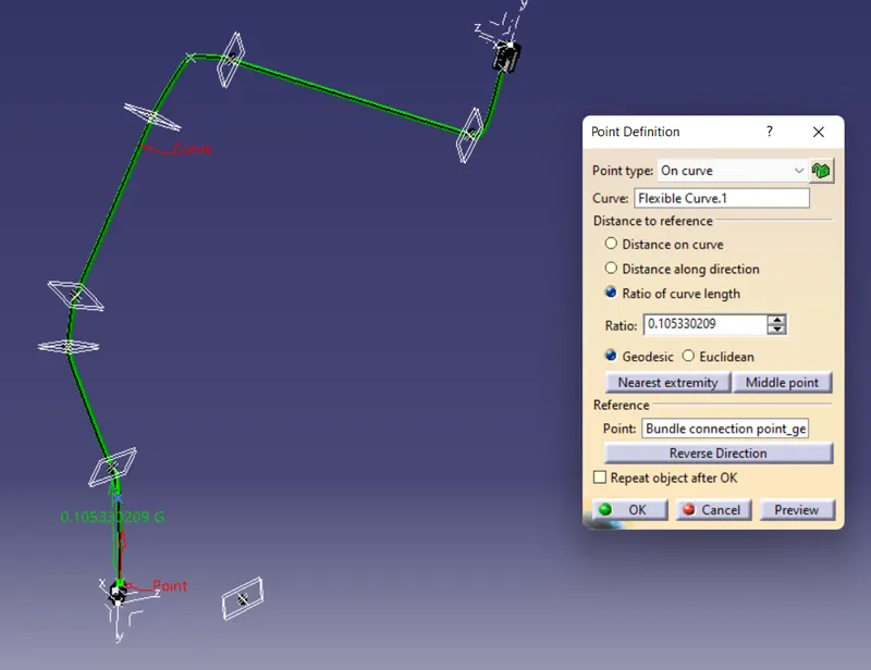
Image : Adding branching points
- Add branch to connect the another tail lamp connector from the main branch as shown below using add branches command and routing definition from the branch point to tail lamp connector through the furr tree clips to complete the routing.
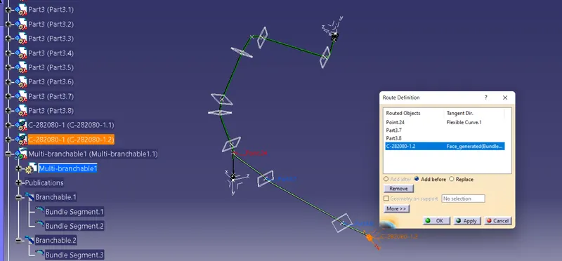 Image : Added branch
- Manipulate the furr tree clips in between to avoid fouling and ensure proper routing inside the tail gate.
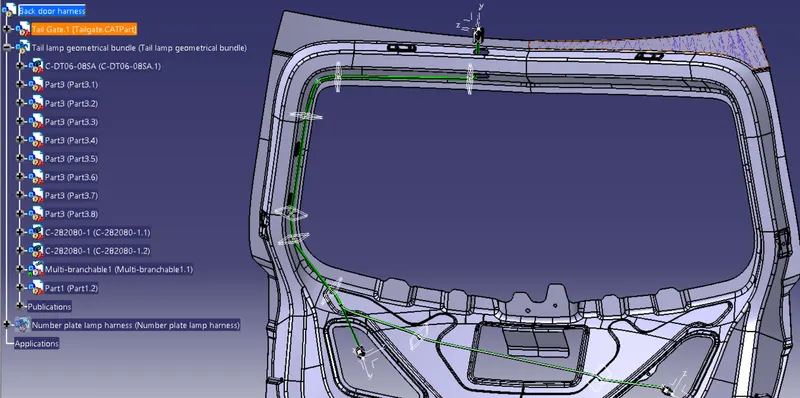 Image : Tail lamp harness routing
- Similarly, the number plate lamp harness routing is done with similar steps as shown in the image below
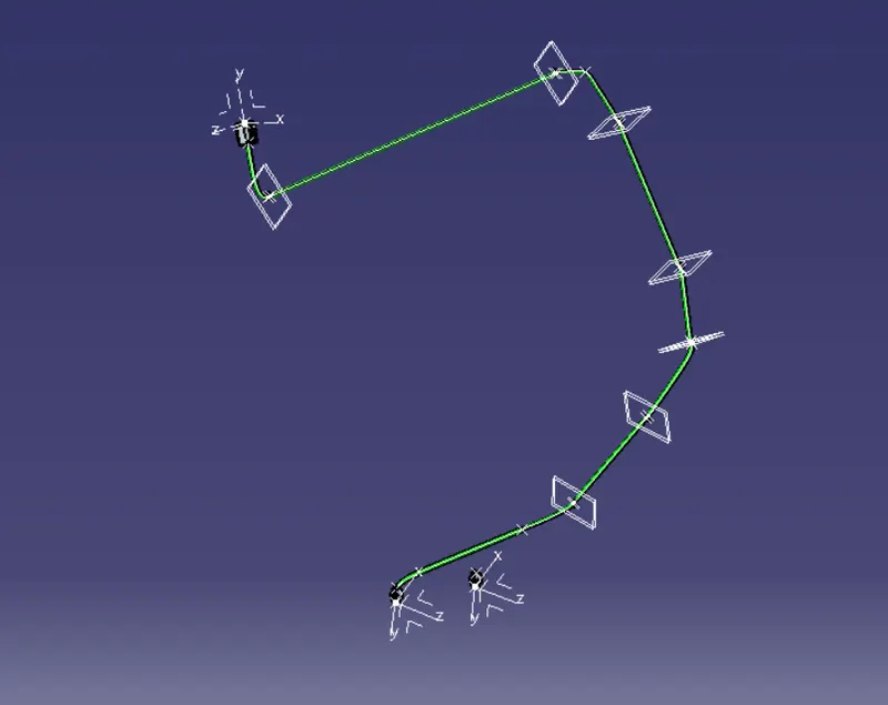 Image : Main branch routing from interconnection connector to number plate lamp connector
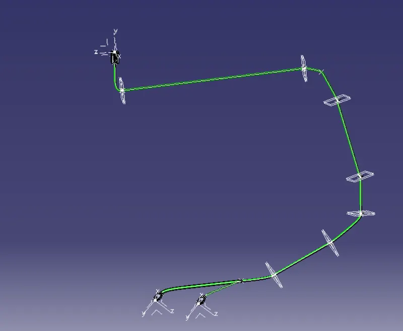 Image : Adding suitable branch point and branch
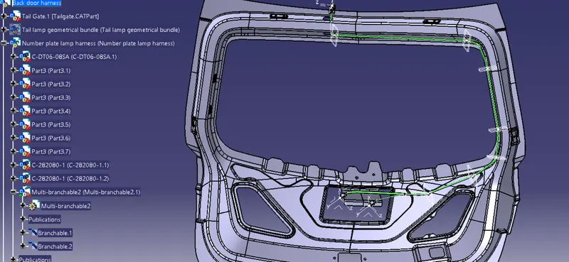 Image : Number plate lamp harness routing
Thus the wiring harness routing is completed
Step 8. Applying protection covering to the harness bundle
- To add protective coverings on the wiring harness, first create a protective covering by using define protection part command in the electrical part design workbench. Select any plane, and define the parameters as per the requirement.
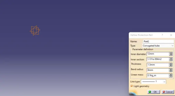 Image : Defining parameters to create corrugated tube
- A corrugated tube is created.
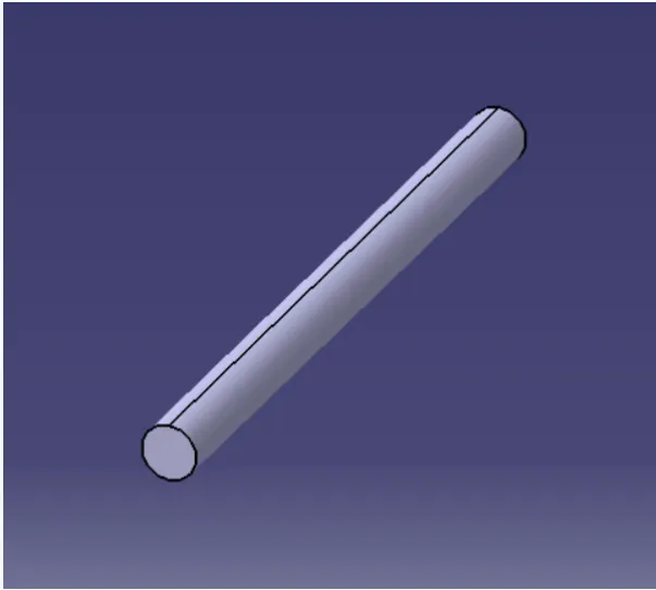 Image : Corrugated tube
- Go to new and select catalog document, select add family command and define the type as conduit save the file to create a catalog for protection tube.
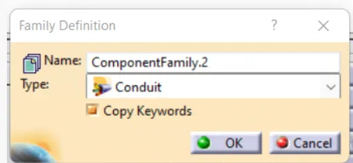 Image : Defining corrugated tube catalog
- A catalog file is created as shown.
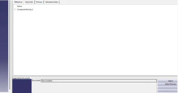 Image : Creating corrugated tube catalog
- Save the file to create a catalog for protection tube.
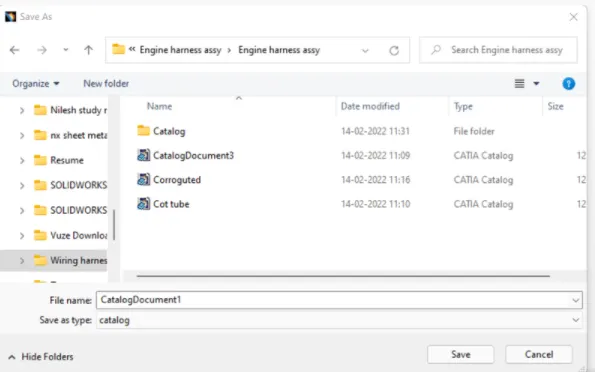 Image : Saving the catalog
- The created corrugated tube can be added into the catalog by store device command and selecting the catalog file created for protection tube which can be used to add protection on the harness as and when required.
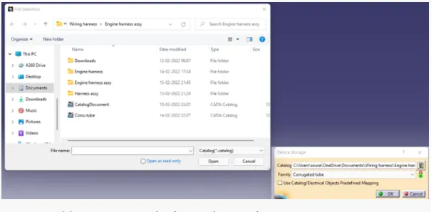 Image : Adding corrugated tube to the catalog
- To add protection tube in the wiring harness, select light protective coverings command and select the required size protection tube from the catalog.
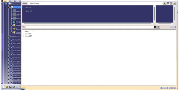 Image : Selecting corrugated tube to apply protection covering
and select the branches where the protection tube is to be applied and the protection tube gets applied on the wirings as shown below.
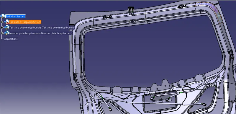 Image : Added corrugated tube to the catalog
Step 9 . Check bundle connectivity
To check bundle connectivity go to edit, select search option, go to advanced tab and select the workbench as electrical, type as bundle segmentand attribute as fully connected and attribute criterion as true if you want to check all connected bundle segments and false if you want to check all the unconnected bundle segments.
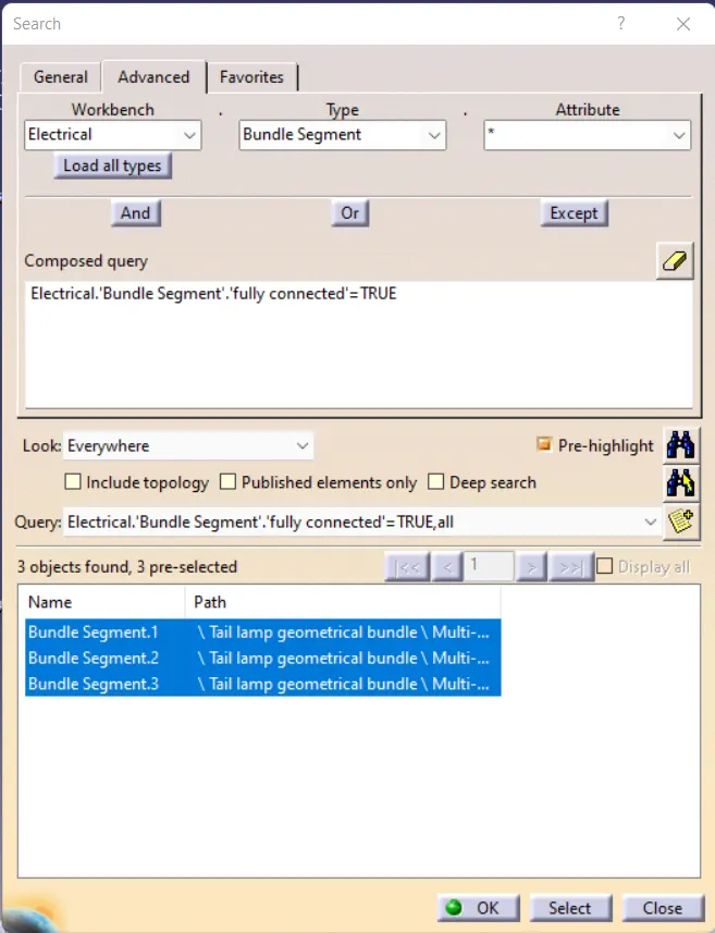 Image : Bundle connectivity checking for tail lamp harness
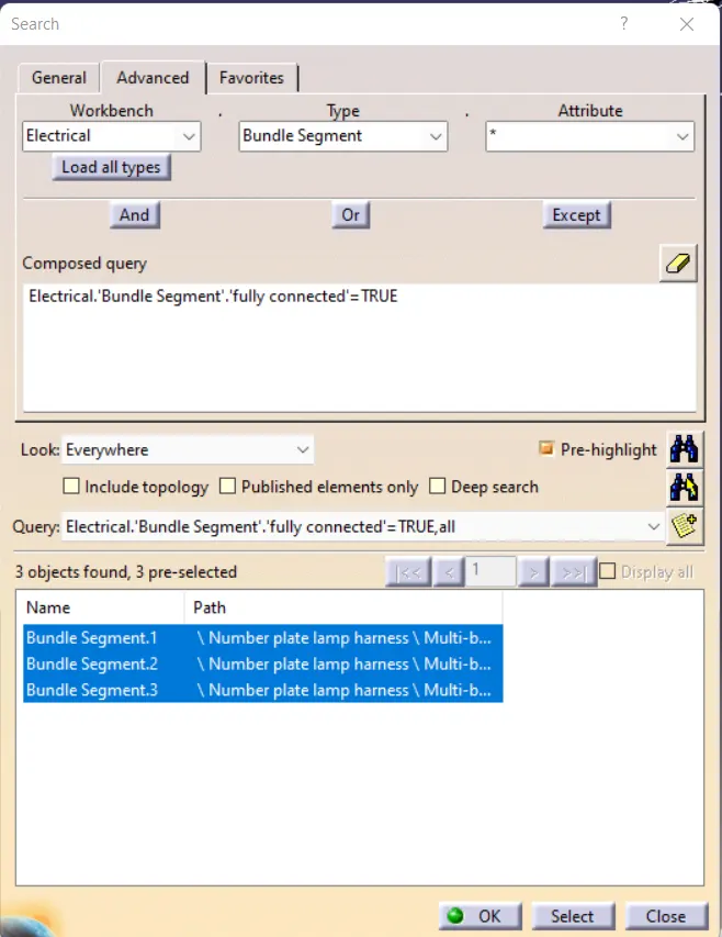
Image : Bundle connectivity checking for number plate lamp harness
Now as the branches are fully connected we can proceed further for harness flattening.
Step 10. To create flatten view of the tail lamp harness
- Create a new product file and save it in the same folder where the wiring harness is saved
- Go to Electrical harness flattening workbench and select harness flattening parameters and define flattening parameters into it as shown in the images below.
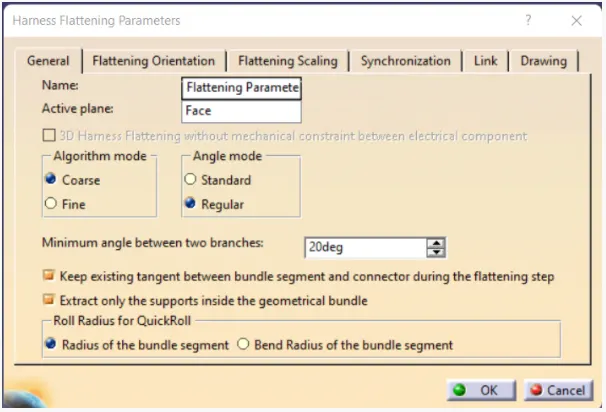
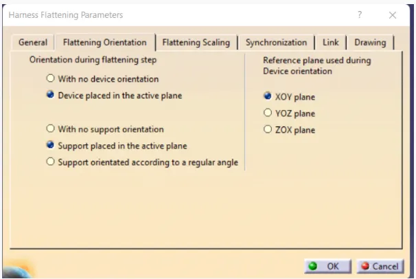
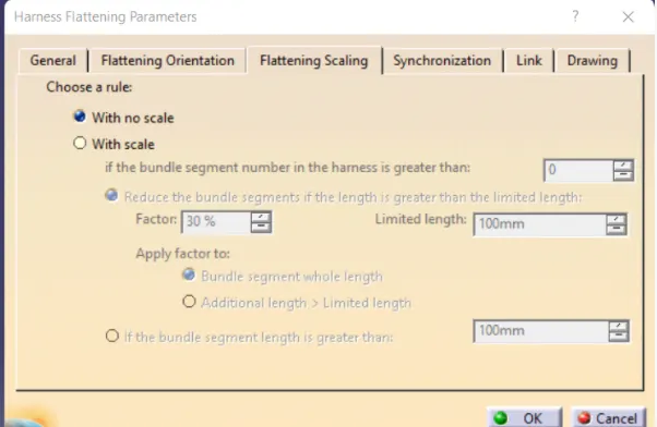
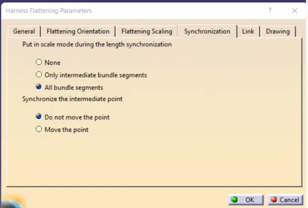
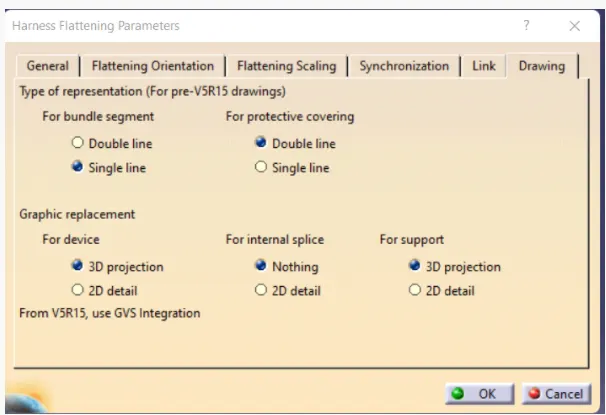 Images : Defining harness flattening parameters
- To import the harness file into the harness flatten file, select extract command and go to harness assembly window and click on the geometrical bundle. The harness routing is added into the harness flatten file as shown below.
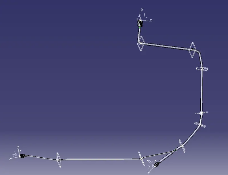 Image : Extarcted tail lamp harness into flattening product file
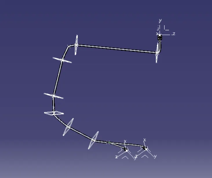 Image : Extarcted number plate lamp harness into flattening product file
- Go to flatten command and select the appropriate face and select all the branches of the wiring harness, the harness is flattened as shown below.
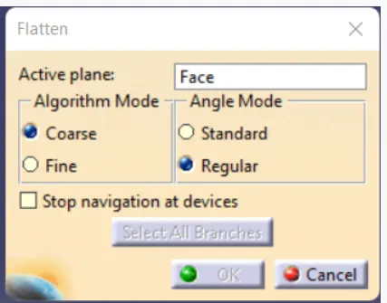
Image : Flatten command defining
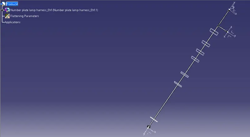
Image : Number plate lamp flattened harness
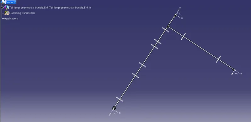
Image : Tail lamp flattened harness
- Use rotate command to rotate the branches and make the wiring harness routing presentable in the drawing sheet. Following which the connectors and other devices are also to be manipulated in the assembly design workbench to give a proper view while drafting on the drawing sheet.
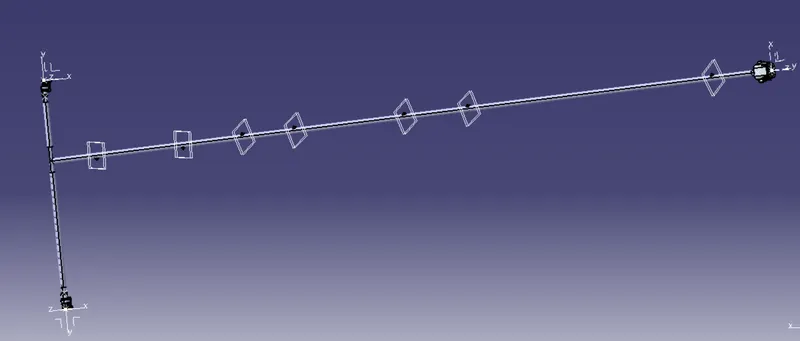
Image : Number plate lamp flattened harness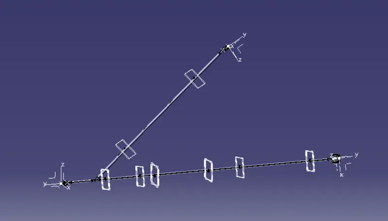
Image : Tail lamp flattened harness
- The flattening view is ready and can be used for drafting.
- Go to assembly design workbench, and select view from reference command and select the plane to add plane for the annotation, select flag note with leader and add annotations.
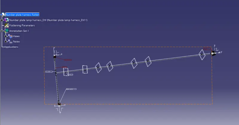
Image : Number plate lamp harness with added annotations
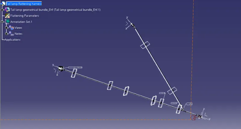
Image : Tail lamp harness with added annotations
Step 11. Create drawing of the flattened harness
- Go to new and select drawing to create a new drawing file.
- Select front view command, go to the flattened harness window and select a suitable face to create drafting of the harness. The wiring harness appears as shown below.
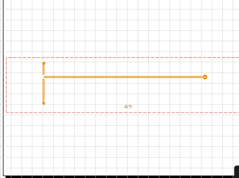
Image : Number plate lamp harness flatten drawing view
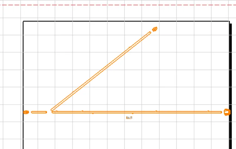
Image : Tail lamp harness flatten drawing view
- To make the bundle segments visible right click on the drawing sheet and go to properties in the view tab, highlight '3D wireframe' and 'is always visible' in the dress up settings.
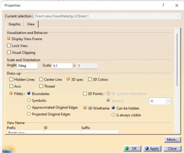
The bundle segment appears in the wiring harness as shown below.
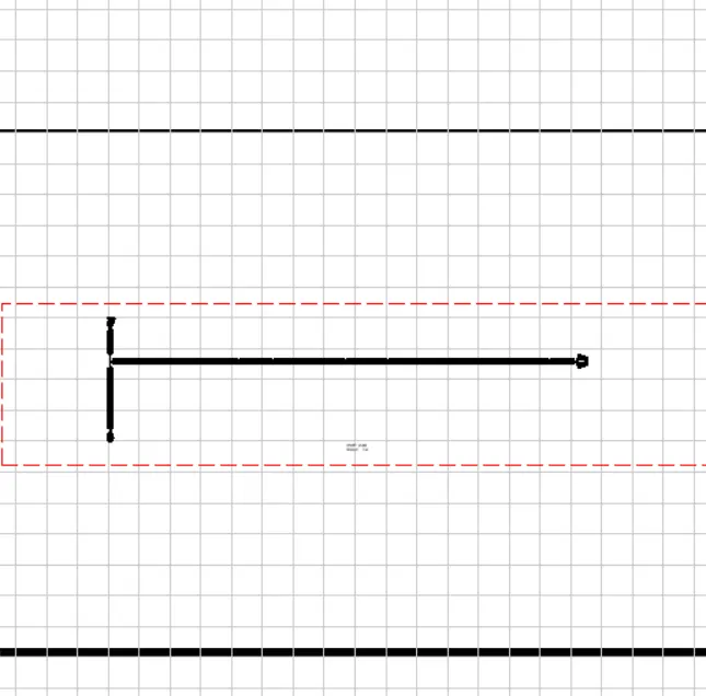
Image : Number plate lamp harness flatten drawing view after highlighting wireframe
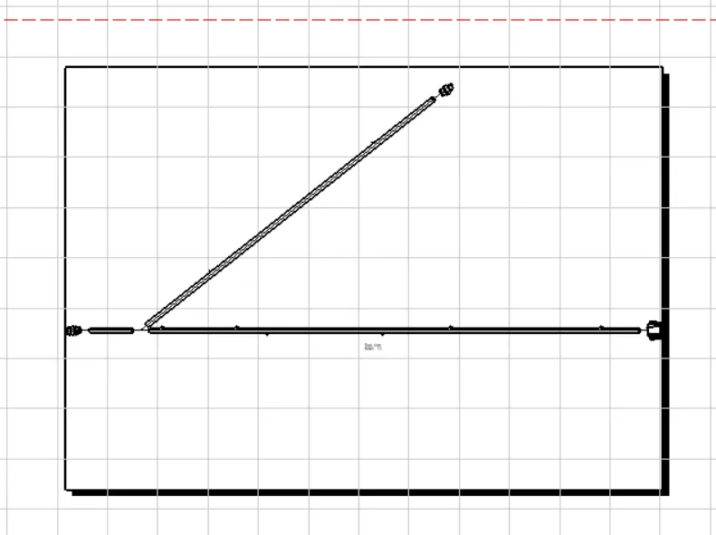
Image : Tail lamp harness flatten drawing view after highlighting wireframe
Conclusion : Thus the tail gate wire harness is completed and the flatten view drawing is created.