Project 2
Routing for Backdoor panel - Project 2
AIM:
Route the Wiring harness on Given car body and Prepare flatten view drawing in CATIA V5. Application of all Packaging rules, Industry best practices studied in this course shall be demonstrated in design. Apply Protection coverings as required.
Available connector 3D data can be used, or you can download the connectors from www.te.com
Wiring Harness:
A wiring harness is a bundled assembly of wires, cables, and connectors used to transmit electrical signals or power in various electrical systems. These harnesses are common in automobiles, industrial machinery, appliances, and electronic devices where there's a need to connect various components reliably and efficiently. The purpose of a wiring harness is to organize and protect the wires and cables from damage, wear, and interference, ensuring the integrity of electrical connections. They typically consist of wires or cables of different colors and sizes, depending on their function, bundled together and secured with insulation, tape, or other protective materials. Connectors at either end of the harness allow it to be easily connected or disconnected from other components in the system.
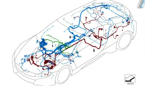
Back door panel wiring harness:
When routing a wiring harness for components on the backdoor of a vehicle, careful planning and consideration are crucial. Identify the locations of all electrical components, such as tail lamps, wiper motor, and latch mechanisms, ensuring the wiring path allows for smooth operation of the backdoor without risk of damage or obstruction. Utilize existing pass-throughs or channels within the vehicle's body to guide the wiring harness from the main body to the backdoor, securing it along the door frame or interior panel with appropriate fasteners. Connect each component according to specifications, testing functionality thoroughly before finalizing the installation. Additionally, weatherproofing measures should be considered to protect the wiring harness from moisture and corrosion. By following these steps diligently, a well-routed wiring harness for backdoor components ensures reliable operation and longevity of the vehicle's electrical system.
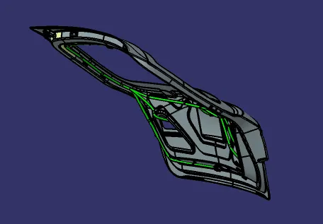
Routing Assembly Creation
Catalog Creation: Download all required connectors and support parts, and create a catalog for the connectors.
Electrical Definition: Electrically define connectors and support parts by creating points, planes, and axes.
Assembly: Assemble the electrically defined parts and connectors in the designated locations for the wiring harness.
Connection: Connect connectors with the wiring harness through support parts, ensuring appropriate bundle radius and slack percentage.
Protection: Cover the wires with suitable protective covers, maintaining proper distance at the start and end extremities.
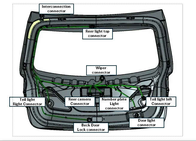
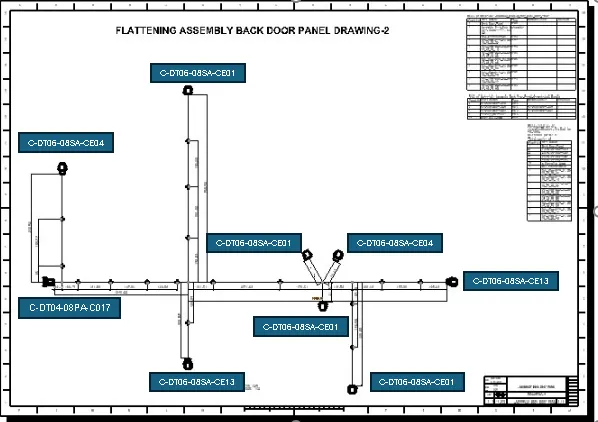
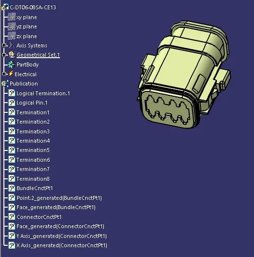
C-DT06-08SA-CE13
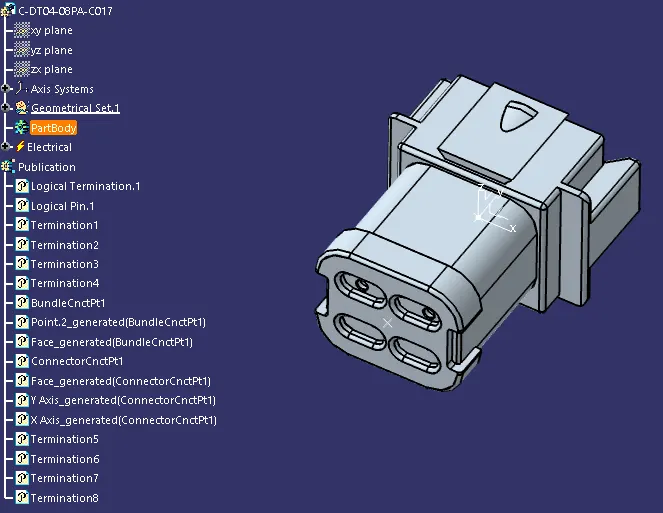
C-DT04-08PA-C017
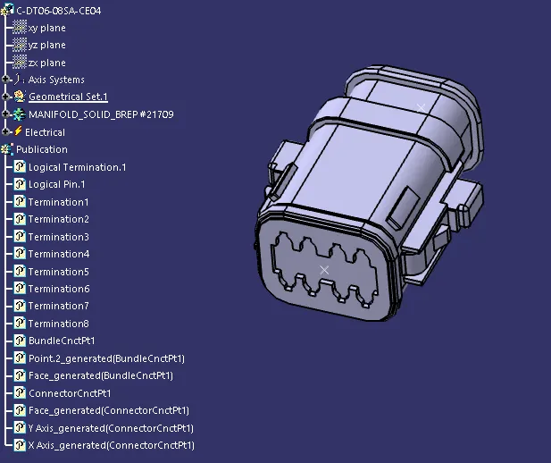
C-DT06-08SA-CE04
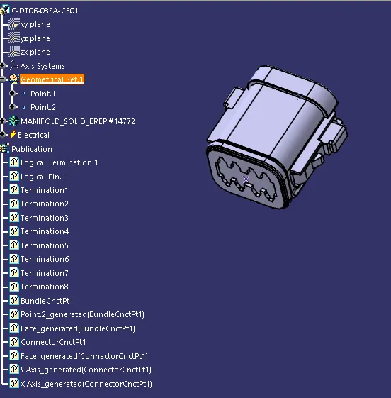
C-DT06-08SA-CE01
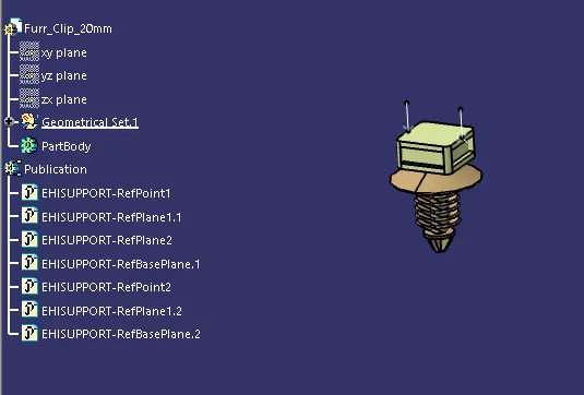
Furr tree clip
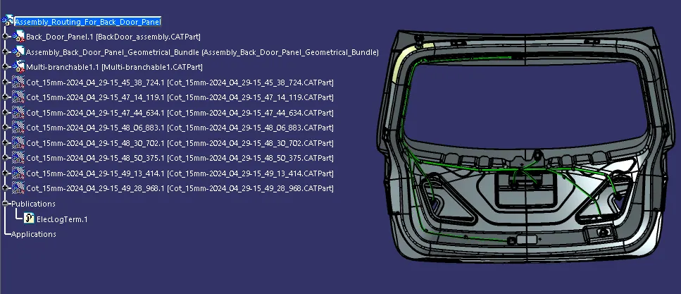
Assembly Routing For Side Door Panel
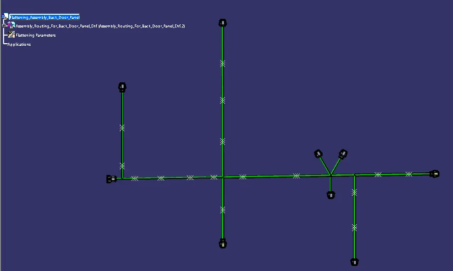
Flattening a Wiring Harness
Flattening a wiring harness in CATIA V5 involves converting the 3D harness representation into a 2D flat pattern for manufacturing and documentation purposes.
Setup: Open a new product file titled [Assembly Wiring Flattening Product]. Switch to Electrical Harness Flattening and adjust settings in the Flattening parameters for General & Drawing at [Harness Flattening Parameters].
Extraction: Tile vertically the (Assembly Routing for Side Door Panel) and use the Extract command to retrieve the necessary components.
Flattening: Use the Flatten command, select the active plane as the Connector Top Plane, and choose all branches. Click OK to create the flattened assembly.
Drawing Creation in CATIA V5
Creating drawings in CATIA V5 involves generating 2D views from 3D models for documentation and manufacturing.
Setup: Open a new Drawing file and rename it as [Drawing 1]. Tile the window vertically with Drawing 1 and the Assembly Wiring Flattening Product.
View Creation: Use the Front View command and select a flat surface in the Assembly Wiring Flattening Product. The flattened drawing (Side Door Panel Drawing-1) will be created.
Details: Add the Bill of Material (BOM), layout, dimensioning, and labels for connectors and clips to the drawing.
Drawing-1
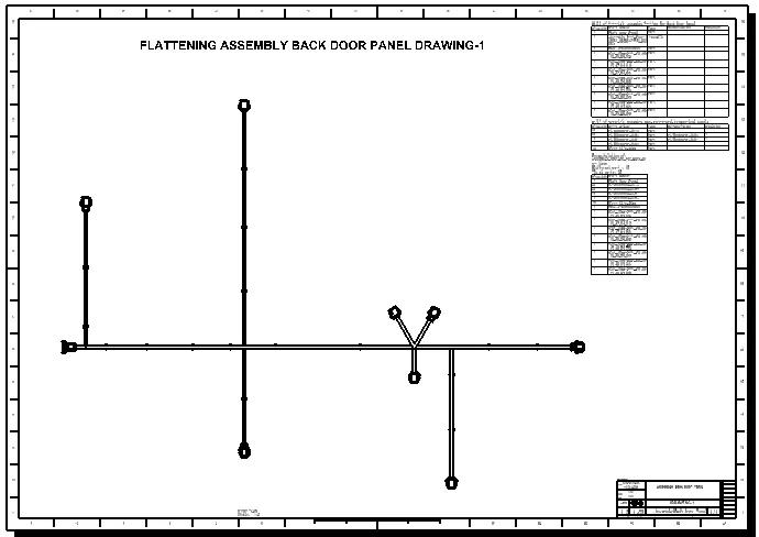
Drawing-2