Project 2
AIM: Route the wiring harness on given car body hatch and prepare the flatten view drawing in CATIA V5.
Objective: This project involves the objective to route the wiring harness on given car body hatch and prepare the flatten view drawing in CATIA V5 with all the necessary contraints applicable in Routing. All the packaging rules and indusrty best parctices shall be considered with necessary data of clearence , clipping/clamping section, Harness fixing requirements, harness continuity and assumptions of 3D data that is required to route the wiring harness on to a given engine.
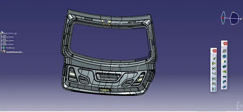 Fig 1
Fig 1
TECHNICAL SPECIFICATIONS AND ASSUMPTIONS:
- Wiring harness routing shall be ease in manufacturing, accessibility, maintainance and removal.
- Aviod routing through small structural holes, bolts, bolted joints, screwed joints to avoid harness puncture
- Provide additional slack to the harness according to the surrounding and harness bending requirements.
- Provide additional slack to the harness branch which connects to the loads and covered with enclosures.
- Avoid routing near sharp edges or over the sharp edges, in case of non avoidable situations addtional protection shoud be provided.
- Ensure harness is routed atleast 100mm away from ABC pedals.
- Enough clips and clamps shall be privided to ensure the positive clearence with surroundings and safety of wiring harness.
- Keep the harness away from engine heat generation components, heating lines and EGR components.
- Avoid direct support of harness on fuel lines routed in engine, in that case a seperator clamp to be provided to satisfy clearence requirements.
- Harness branch length should minimum 50mm.
- Minimum distance between clip and nearest branching point should be 25mm.
- Limit the number of branches from single branching point to 4.
- Harness Protection should be provided according to the surrounding temeperature.
- Clips/Clamps that are used should be selected such that they are easily available in the market.
The given car body hatch focuses on different areas of study under which comprises of routing harness bundles for two taillamps and two number plate lights which connects the car main electrical system.
For all these four lights a Deustch 2 pole connectrors are used (DT06-2s) and a an Interconnection connector which connects from car body hatch to the main car body wiring harness and is used at a preferred location from where the routing for these lights starts. For interconnection 12 pole connector is used.
As for the mounting parts clips/clamps which are used where ever necessary, hellerman mounting clip and fixing clips are used.
This car BIW body requires a lot of mounting hole provision for he clips, it should be discussed with BIW design team and should be asked for these extra features and it will be finalised by the BIW design team.
CONTENTS:
Step1: Creating Car body context assembly and Geometrical assembly
Car body hatch context assembly contains 3D data of car body hatch and all the non electrical data are stored in it and also the geometrical bundle assembly which consists of the electrical data needed for the project.
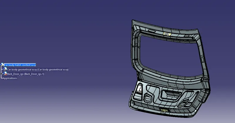
Fig 2
Step2: Defining 2 pole connector electrically.
The 2 pole connector DT06-2S is used for 4 lights 2 for taillamps and 2 for number plate are defined electrically with all the bundle connection point and connector connection points, as shown in the fig below.
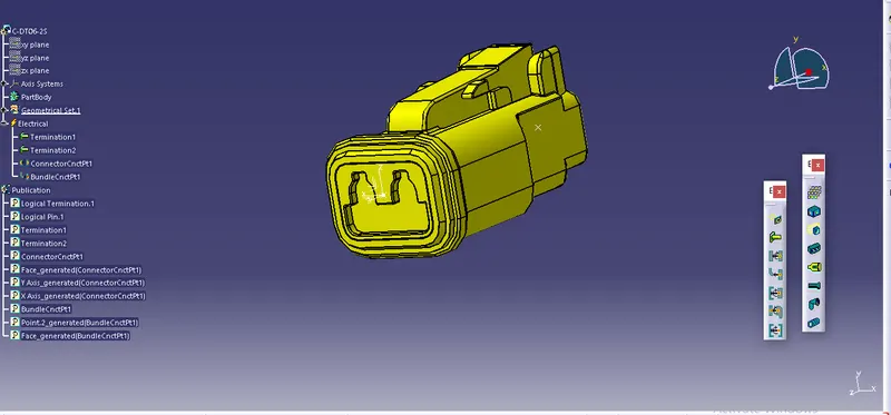
Fig 3
Step 3: Placing connectors for two tail lamps and 2 license plate lights
Two pole connectors are placed for each of two tail lamps and license plated using manipulation, snap and smart move tools as shown in the fig below.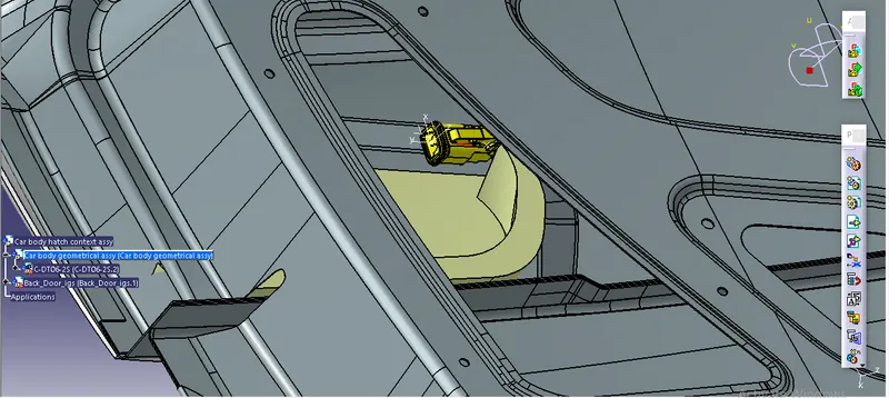
Fig 4

Fig 5
Step 4: Defining Interconnection connector and cavity
The Interconnection connector used here is C-776438-4 12 pole and cavity used for this connector is C-1924487-2 are defined electrically with all the bundle entry points connector connection points and cavity connection points and connected electrically as shown in the fig below
The bundle routing starts from interconnection connector.
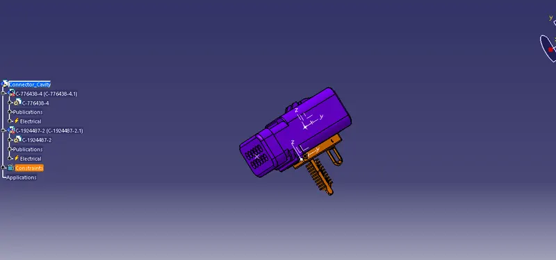
Fig 6
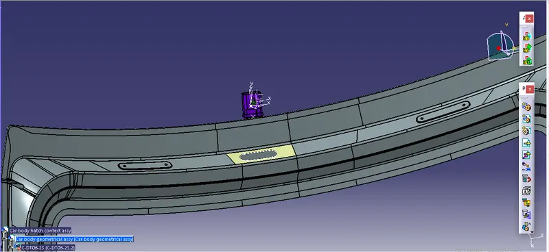
Fig 7
Step 5: Defining Clips as support
For mounting purpose hellermann fixing mount clip with part no. 151-40119 and hellermann fixing clip with fir tree part no. 155-30802 is used. All the necessary wire entry and exit points are created along with entry plane, exit plane and base plane and defined electrically as supports.
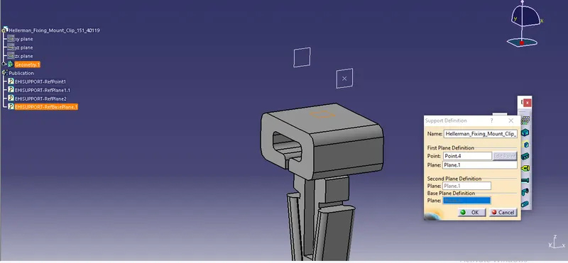
Fig 8
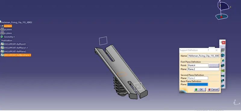
Fig 9
Step 6: Placing or mounting clips in the preferred locations of tail gate
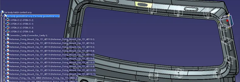
Fig 10
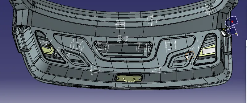
Fig 11
Step 7: Bundle routing from interconnection connector to all the connectors arranged and all the mounting clips
The dimensions assigned for bundles, like diameter and bend radius are assumed and actual values are provided at a later stage. From the below figure it is seen that the routing starts from the interconnection connector and goes throung all the clips and then to the all the connectors.
The bend radius for all the bundles is assumed to be 1.4mm
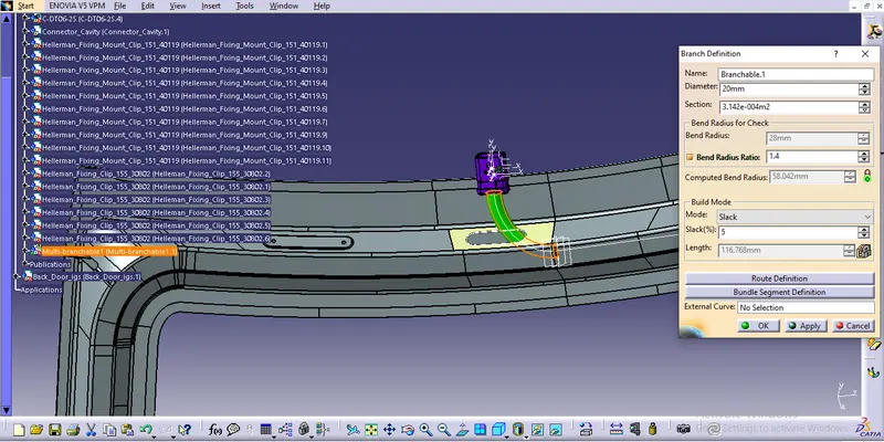
Fig 12
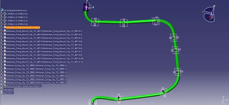
Fig 13
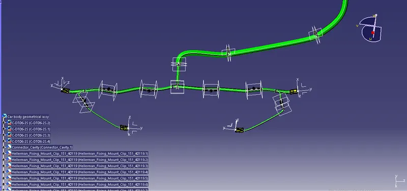
Fig 14
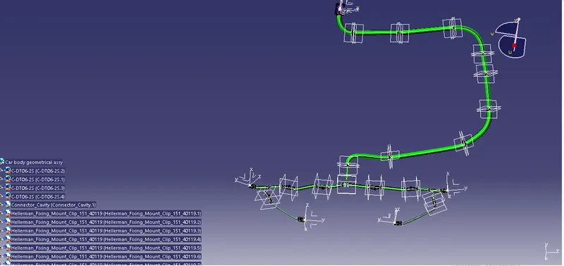
Fig 15
Step 8: Adding protective coverings to the bundles
Protective coverings are added to the bundles to avoid any damage, wear and tear to the bundles which might happen during opening and closing of door. In this case blue color PVC tapes are used with start and extremity given wherever necessary through out the bundles as shown in the fig below.
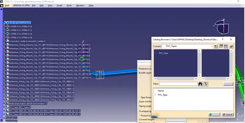
Fig 16
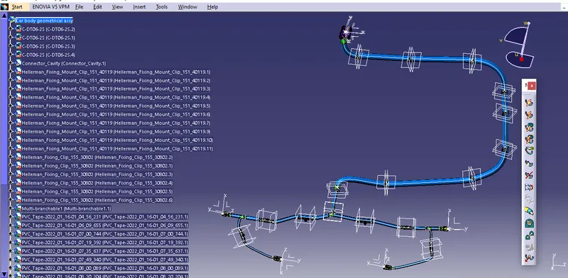
Fig 17
Step 9: To check bundle continuity
Go to edit>Serach>Advanced>Electrical workbench>Type-Bundle segment>Attribute-Fully connected
Selecting True will show all the bundles that are in continuity and fully connected and False will the non connectivity of bundles
When selected true all the bundle segments are found to be fully connected, and didnot shown any discontnuity in the bundles when selected false condition as shown in the figure below.
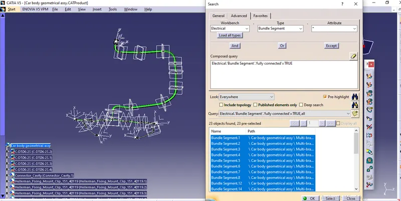
Fig 18
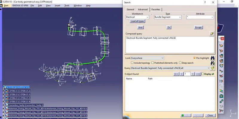
Fig 19
Step 10: Creating flatten product and Flatten drawing view of harness assembly
Flattened product is 2D representation of harness bundles along with all the electrically defined equipments to present it on piece of drawing paper.
To create flattening product of the assembly working bench should be Electrical harness flattening, name the new product as car body hatch flattening assy and define flattening parameters as shown in the figure, and make sure to use single line foe bundle and double line for PVC tapes for better differentiation.
Once the parametrs are defined , the geometrical bundle assembly should be extarcted in to the flattening product by using the extract option in the work bench. Once the assembly is extracted use the flatten option to flatten the entire assembly.
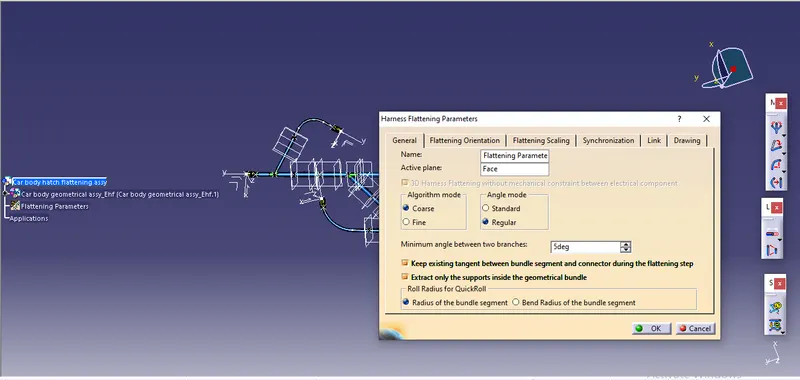
Fig 20
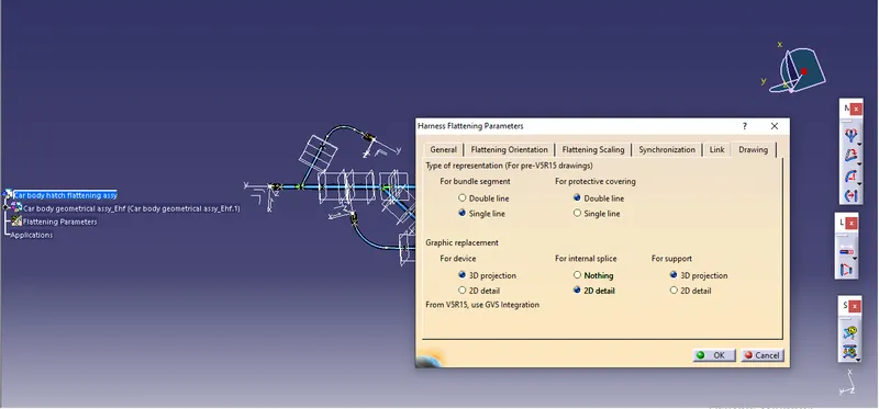
Fig 21
Once the flattened product is obtained make all the necessary changes like scaling, rolling, rotating, straightening etc. Now transfer the flattened assembly on to the 2D drawing sheet by creating new drawing sheet and save the drawing sheet in the same location as all the files saved before.
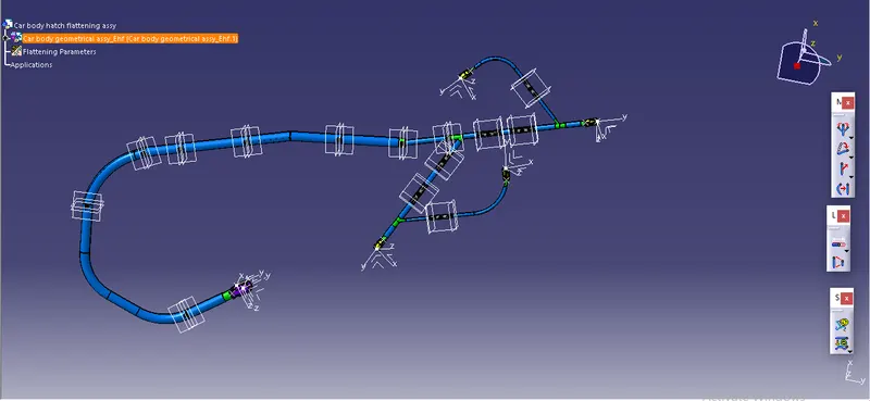
Fig 22
Now select the front view option and select the plane of the flattened which was selected earlier in the flattening properties.
Now the 2D diagram of flattened model is displayed on the drawing sheet, now to go the that drawing properties and in the view section make sure 3D wire frame is always ON which represents the bundles and make sure the graphic for device is 3D projection for better identification and understanding and single line for bundle and double line for protective coverings, and 3D colors can be added for better look as per the image shown below.
The connectors namings can also be given by selecting the text option, and drawing frame and title block, BOM table can also be added for better understanding.
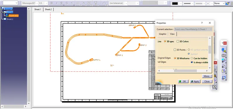
Fig 23
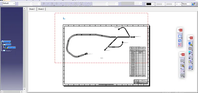
Fig 24
Conclusion:
Routing of wiring harness for car body hatch is done and flatten view for harness assembly is created in CATIA V5. In the process of this project various packaging rules and constraints are considered for routing the wiring harness. Industry best practices are considerd while designing wiring harness. Every minute details and major details like clipping and clamping section, Clearences, harness fixing requirements, bundle continuity are all considered in this design process.