Project 2
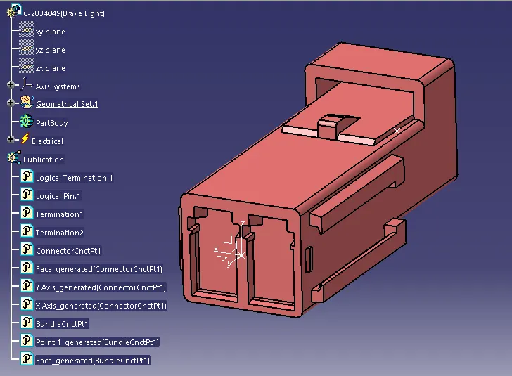
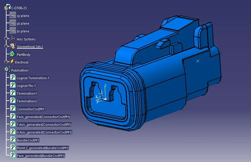
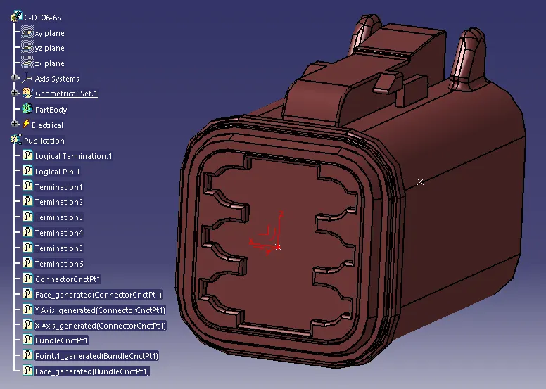
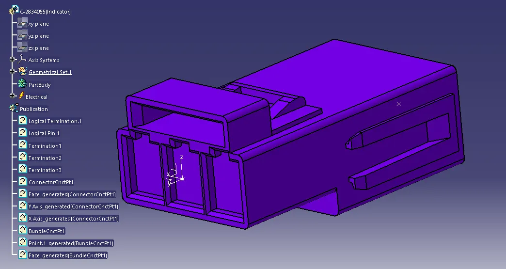
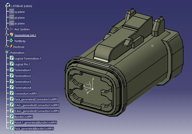
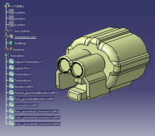
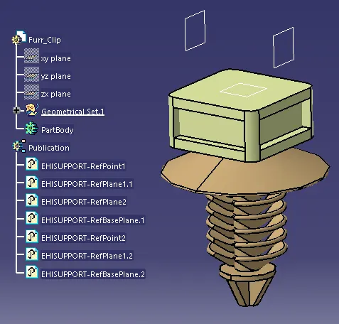
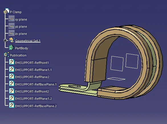
In above slides, all connectors, clips & clamp which used in Back door wiring harness are electrically defined, geometry given with the help of point and axis system, electrially defined through define connector and bundle connection point and connector connection point.
-----------------------------------------------------------------------------------------------------------
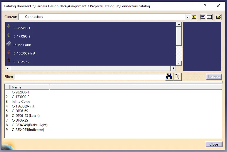
Catalog created and all electrical defined connector saved in catalog for easy use.
-----------------------------------------------------------------------------------------------------------
After all components electrification done. Followed steps to create routing files.
1) Created one product file named context file.
2) Created one another product file which is part of context file & named WH assembly (Geometrical Bundle).
3) Downloaded stp file of door assmebly converted in part file and copy pasted in context file.
4) All electrical components loaded in geometrical bundle file for positioning of all components with the help of door assembly available in context file.
Please refer below snip.
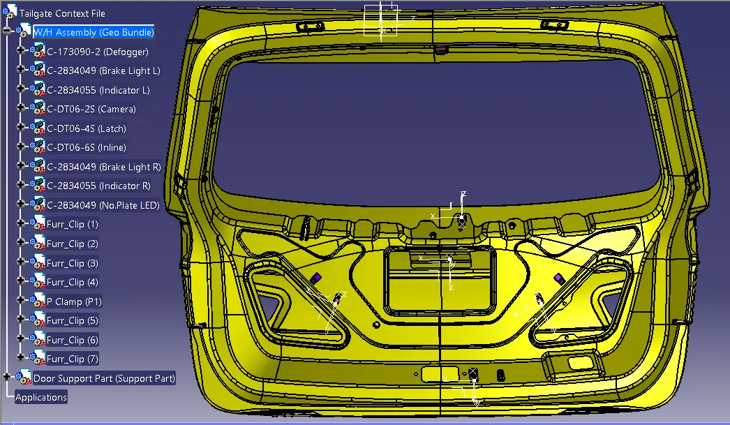
In above slide, all components placed with the help of smart move, manipulation & compass tool. While doing placement of components, geometrical bundle should be activated in context product file.
-----------------------------------------------------------------------------------------------------------
After positioning of all components, geometrical bundle file converted in electrical file by geometrical bundle command available in electrical harness assembly workbench.
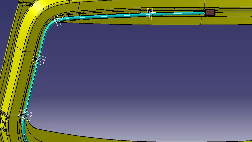
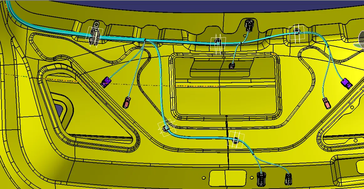
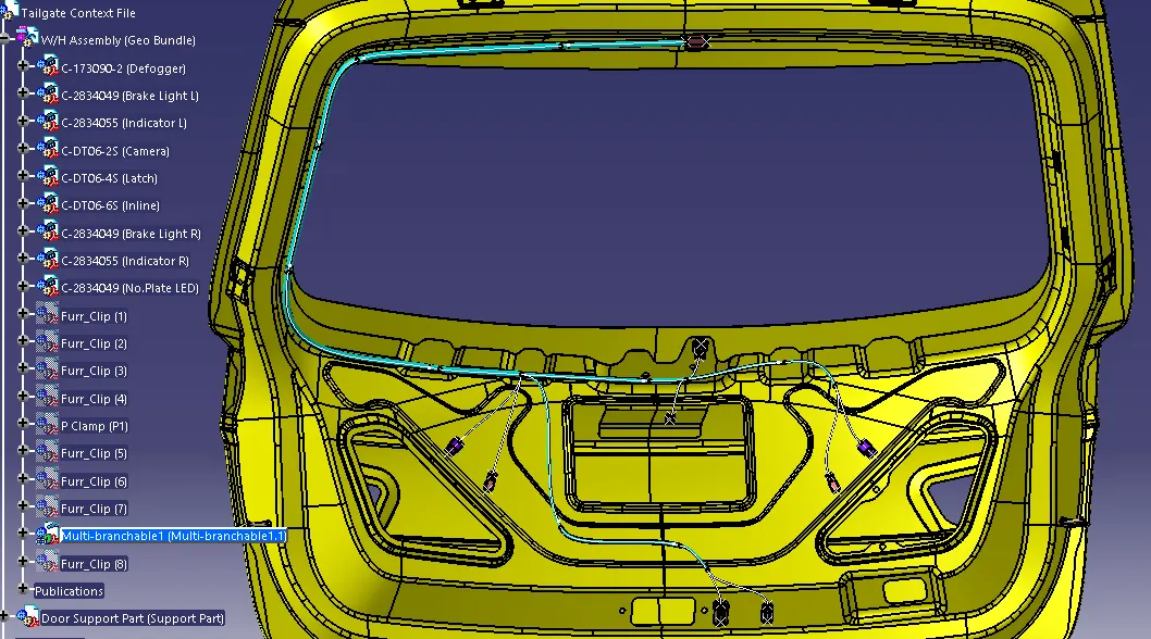
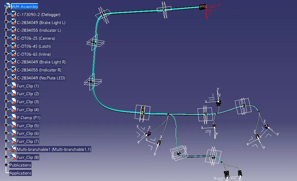
In above slides, after converted geometrical file electrically, started creating bundle routing through clips and clamps positioned over back door assembly. In routing process starts from Branch defination command, through which Multibrancheble file created. After all budles created of main branch, used "add branch point" to create sub branches to other sensors connectors.
-----------------------------------------------------------------------------------------------------------
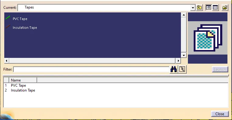
In above slide i created one catalog for tapes which will be use on bundle for protection covering.
-----------------------------------------------------------------------------------------------------------
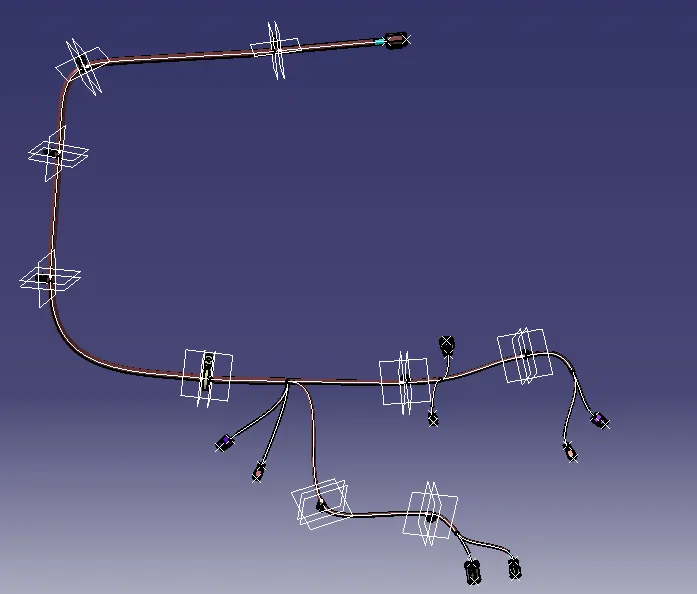
In above slide, all bundles are protected with cotton tape, extrimity defined on all end branches.
-----------------------------------------------------------------------------------------------------------
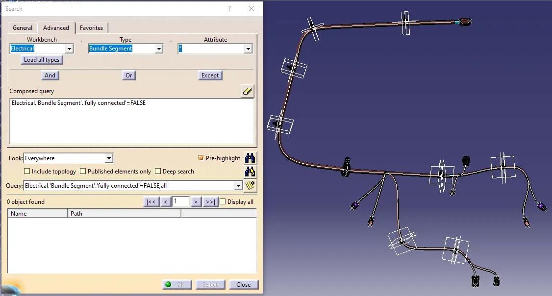
In above slide, bundle continuity checked through search command available in edit option available in tool bar. For continuity check, go to advance, select workbench as electrical, select type as bundle segment and select attribut as fully connected, then select true/false in popup window and click on search. With this way we can conclude that bundles has fully connected.
-----------------------------------------------------------------------------------------------------------
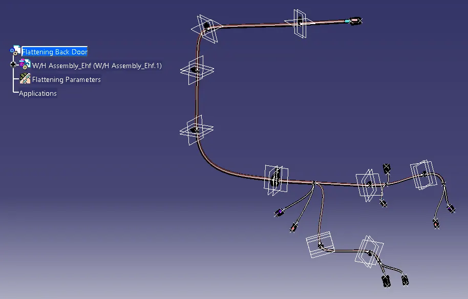
To create flatten model of geometrical bundle, first have to create one product file and saved as flatten file, open electrical harness flattening workbench and defined flattening parameters through harness flattening parameters command. Then tile vertically flattening file and geometrical bundle file and extract WH assemmbly in flatten file through extract command.
Below is the extracted geometrical bundle in flattening file. "W/H Assembly_EHF(W/H Assembly_EHF.1)
-----------------------------------------------------------------------------------------------------------
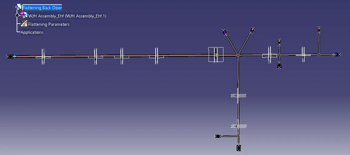
In Above slide extracted geometical bundle converted into flatten modle through flatten command available in harness flattening workbench.
-----------------------------------------------------------------------------------------------------------
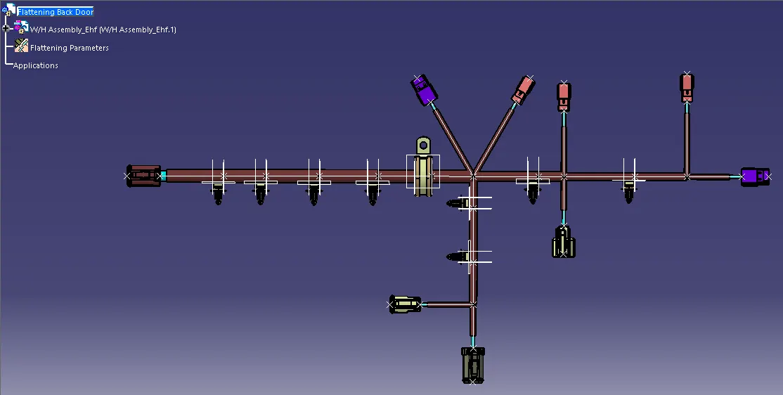
In Above slide all connectros, clips and clamps re-positioned through compass for better recognize. Also it helps clear view in 2D drawing.
With the help of scaling command representation of bundles keeps lower than actucal length for proper fit in drawing sheet. There are other commands available in harness flattening workbench as rotate, quick roll, bend ect for flattening to fit in drawing sheet.
-----------------------------------------------------------------------------------------------------------
To create 2D drawing, first create one drawing file, select sheet as per requirement. Save file as 2D drawing back door.
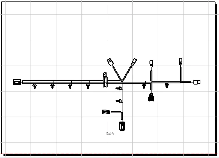
In above slide, to create 2D drawing, first select view as pront view and then select any plane of component in flattening file, then position flatten view in drawing sheet and click on the sheet. 2D representation of W/H Assembly will be available in drawing sheet. For protection covering i kept double line representation, single line for bundles. To enable bundle representation in drawing sheet, go to front view properties, in dress-up option enable 3D Wireframe and select "is always visible"
-----------------------------------------------------------------------------------------------------------
Thankyou