Project 2
Statement of assignment:
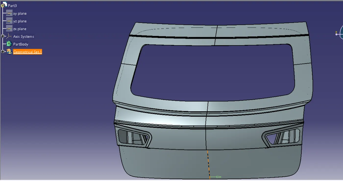
Route the Wiring harness on the Given car body and Prepare to flatten the view drawing in CATIA V5. Application of all Packaging rules, Industry best practices studied in this course shall be demonstrated in design. Apply Protection coverings as required.
Available connector 3D data can be used, or you can download the connectors from www.te.com
Prepare & Submit all necessary reports like clearance, Clipping/Clamping selection, Harness fixing requirements, Harness continuity, and Assumptions if any along with CATIA 3D data.
To Define the Connectors
Here, according to the requirement, we are using
- ‘C-776438’ Which is a 12 Pole connector is used as an inline Connector
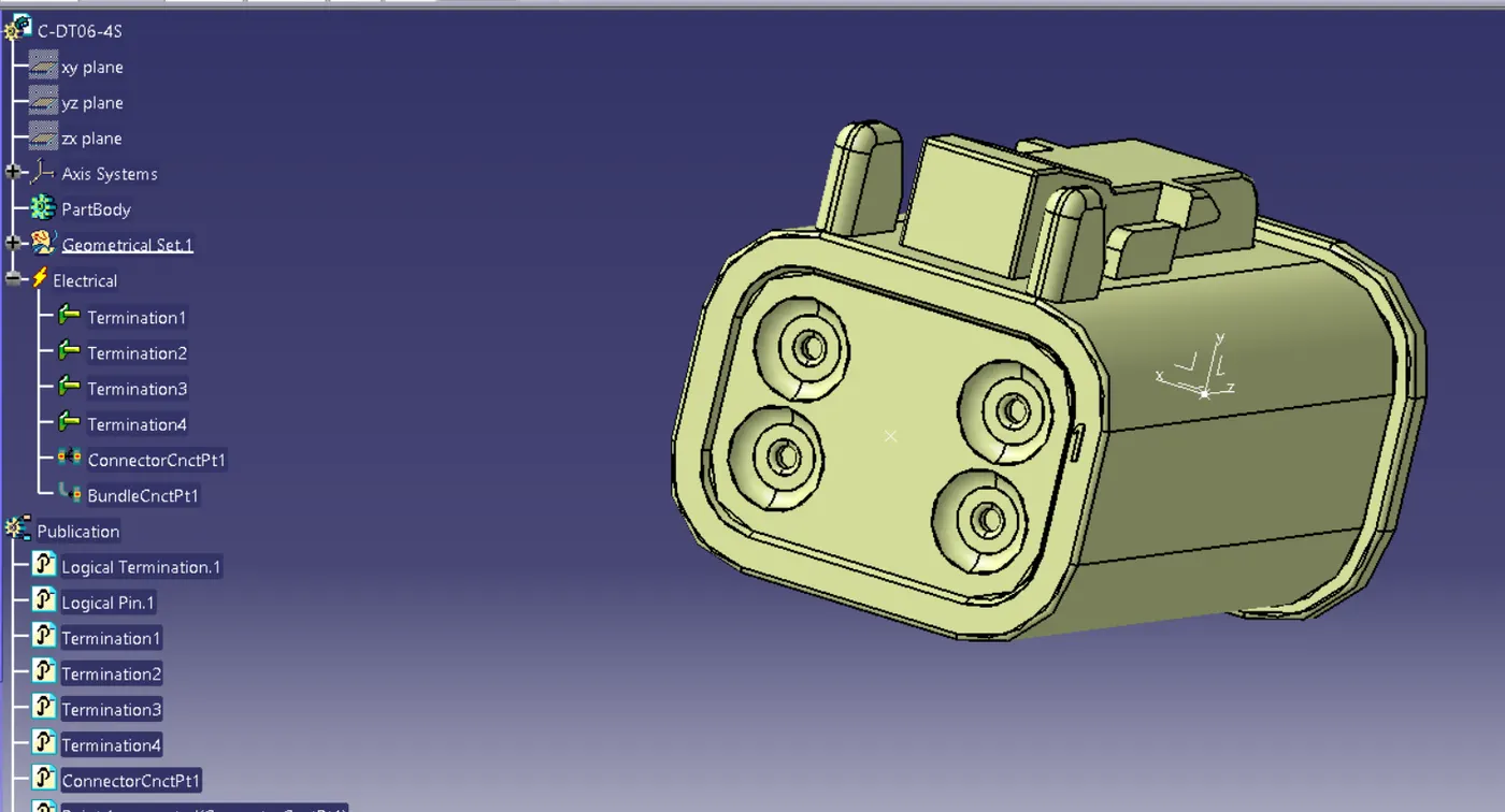
- 'C-DT06-4S' which is a 4-pole connector for Taillight
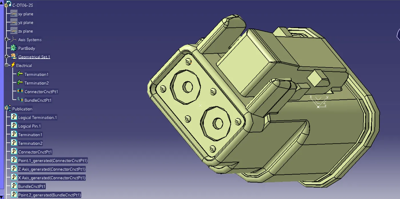
- 'C-DT06-2S' which is a 4-pole connector for Number Plate Light
This CAD data was obtained from te.com. To electrically define a connector, we must first define the geometrical parameters such as the bundle connection point and connector connection point in the Electrical Part Design workbench for the downloaded connector.
‘C-776438’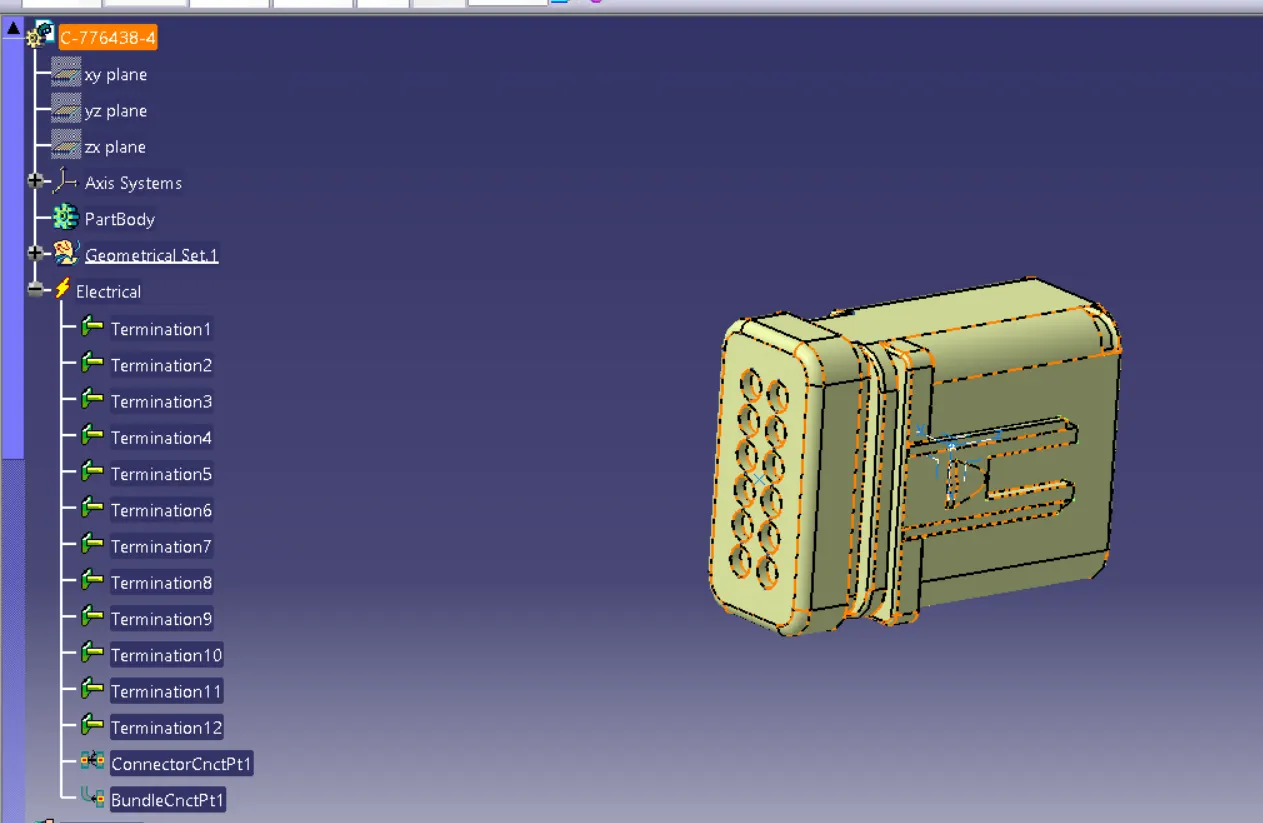
C-DT06-4
'C-DT06-2S'
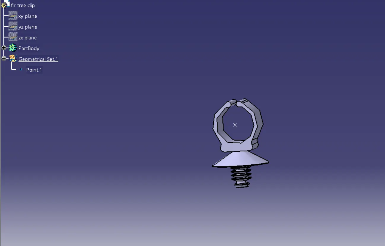
SUPPORT CLIP
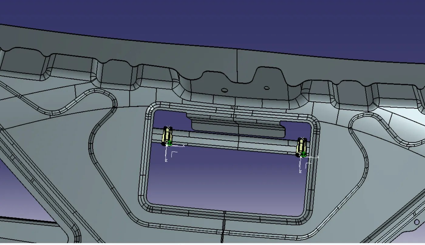
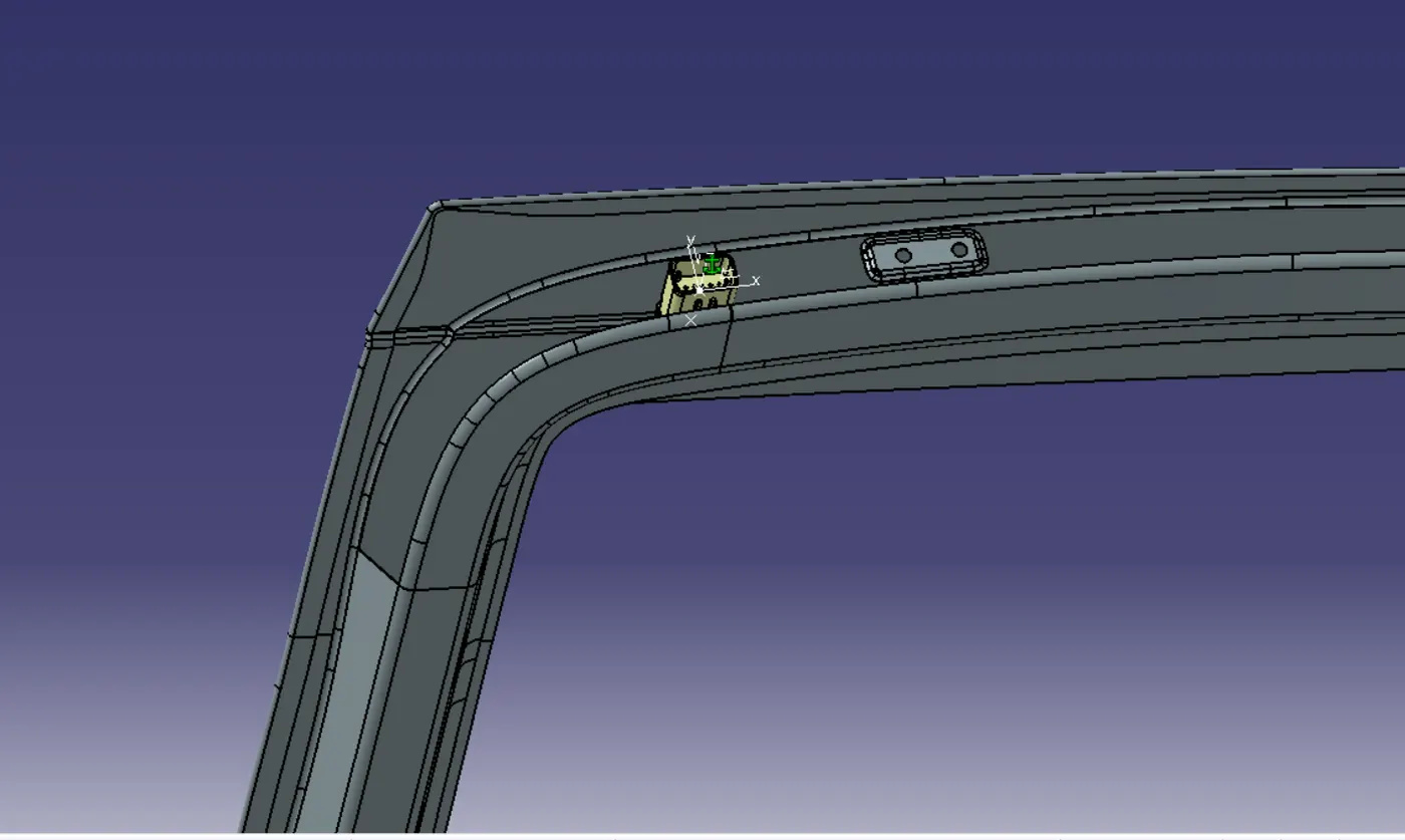
CONNECTOR PLACEMENT
Bundle Routing:
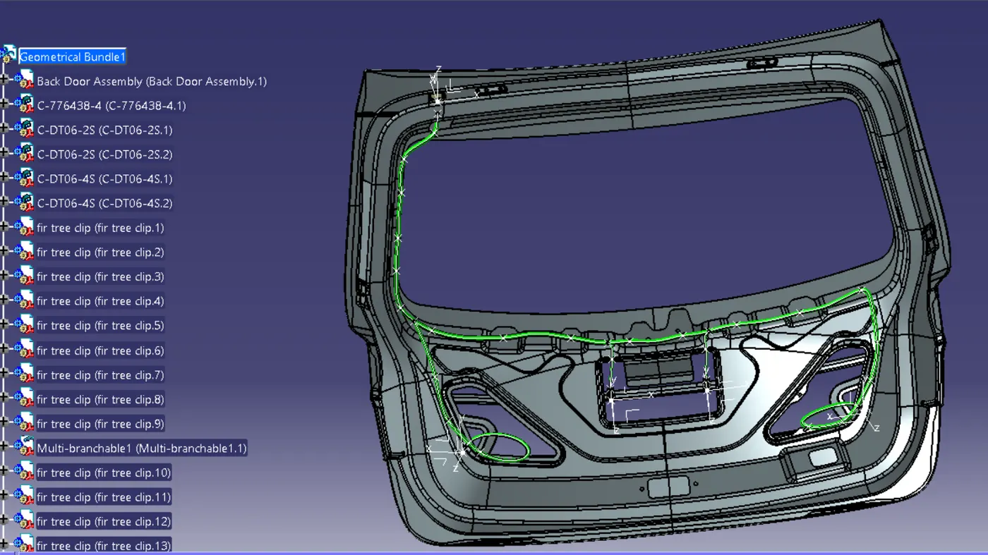
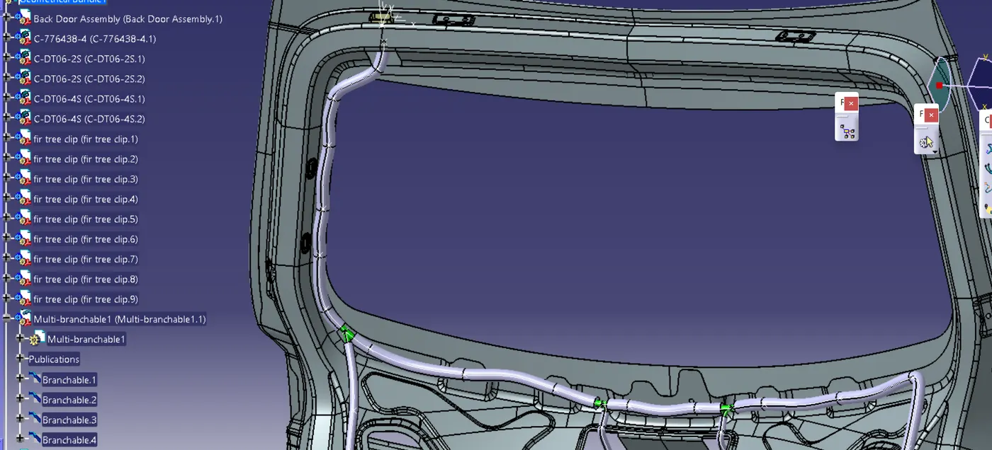
Adding protective coverings and guiding channels top shell to harness bundle
Here is the below figure, we have done with the whole wiring harness routing for the Backdoor. Now, we have to add protective coverings to all bundle segments
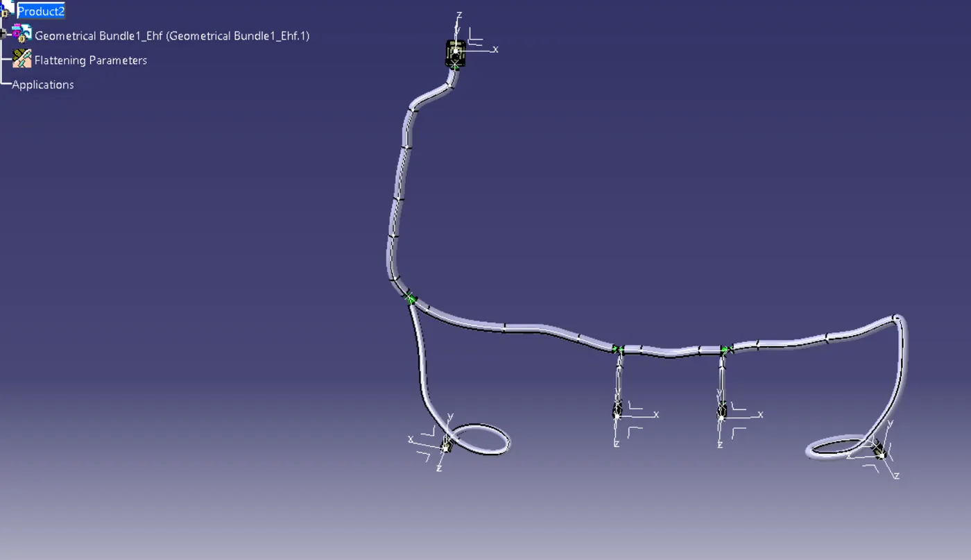
Creating flatten view of the Backdoor Wire harness geometrical bundle assembly
In this step, we will use Catia V5's Electrical Harness Flattening workbench to create a flattened view. We should also ensure that the flattening file is saved in the same folder as the other harness assembly files.
- The bundle assembly was extracted into a Back door wire Harness Flattening Product file, which was then flattened along the face of the interconnection connector.
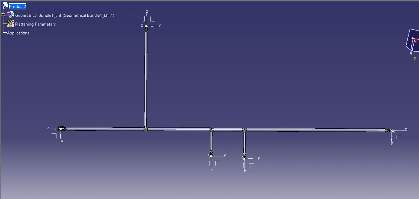
- We developed a flattened view.
- we must rotate bundle segments connecting to the four cam-shaft connectors using the 'Rotate' feature of the flattening workbench.
- It should be noted that the 'face' of the interconnection connector serves as the flattening plane, so we must rotate the bundle segments only along that plane.
- We used various features such as bend, rotate, and roll to streamline the harness for better representation.
The flattened view's final representation
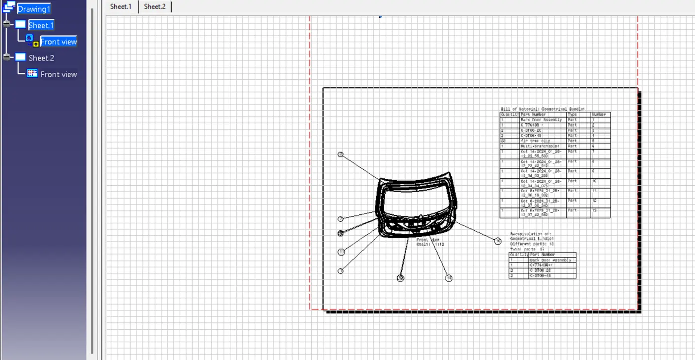
DRAFTING