Wiring harness design in CATIA V5 - 3D modeling Week 7 Challenge
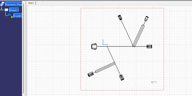
AIM: To create a flattened view of the harness assembly given in figure.
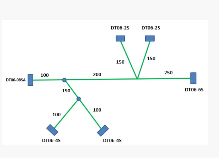
Step 1: Create a seperate product file in Electrical Harness flattening workbench for flatenning the harness assembly. Fig 1
Step 2: Define harness flattening parameters. Fig 1
- Select single line representation for bundle segments, and double line for protective coverings.
For devices- 2D detail is selected and for support - 3D projection is used.
Step 3: Using "Extract" feature bring the harness assembly into the flattening file. Fig 2
Step 4: Use the "Flatten" command. Fig 3
-Select the plane to flatten (XY plane is selected) and select all the branches for flattening.
Step 5: Change the position of bundle segments to the desired position. Fig 4
- Use "Rotate" command and rotate the bundle segements in the XY plane.
Step 6: Place the flattened view on drawing sheet. Fig 5 and Fig 6.
- A new drawing file is created in A0 ISO format and create a 2D front view of the desired plane where, bundle segments are represented with single line and protective coverings are represented with double lines.
Fig 1
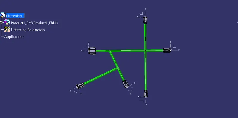
Fig 2
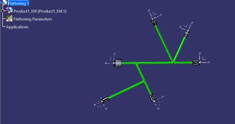
Fig 3
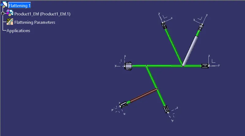
Fig 4
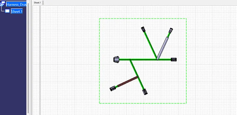
Fig 5
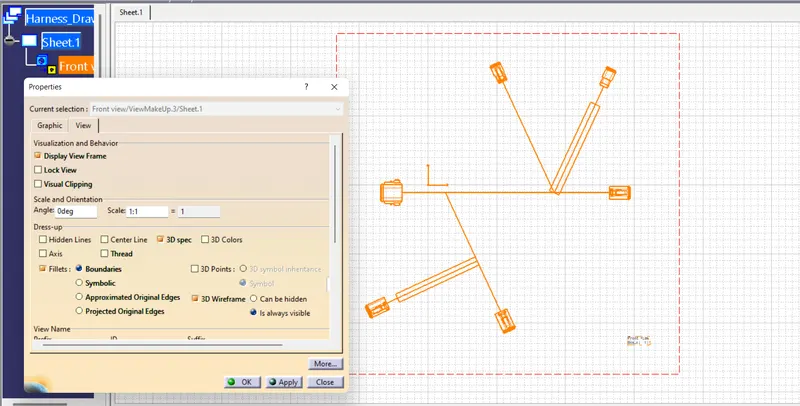
Fig 6