Wiring harness design in CATIA V5 - 3D modeling Week 5 & 6 Challenge
HARNESS ASSEMBLY & INSTALLATION
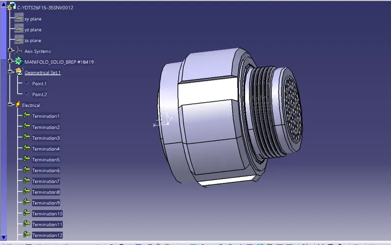
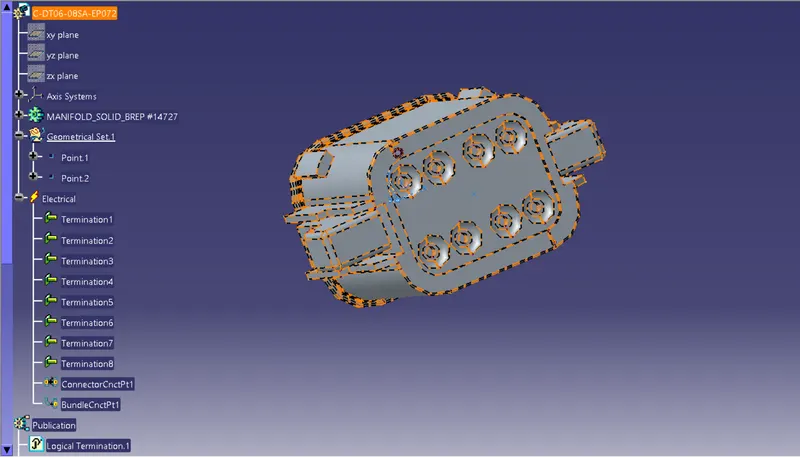
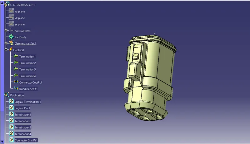
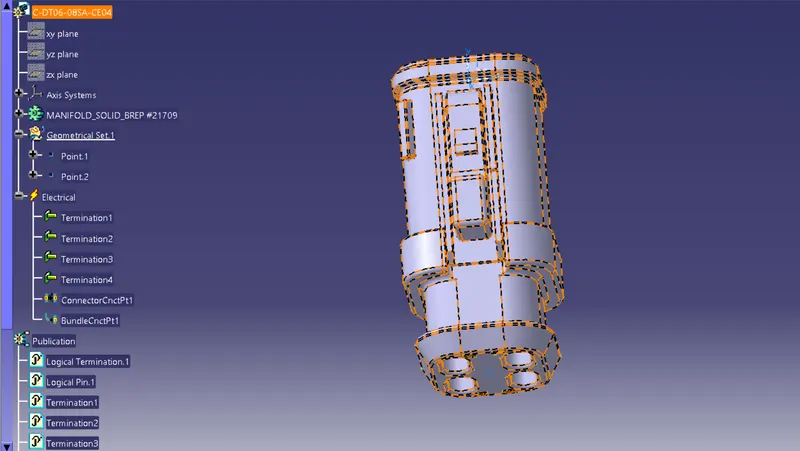
The following connectors are used in harness layout in Electrical workbench.
- C-YDTS26F15-35SNV001-99
- C-DT06-3SA-CP01
- C-DT06-08SA-CE04
- C-DT06-08SA-EP07
- C-DT06-08SA-CE13-99
- C-DT04-08PA-C017-99
- C-1-174357-2
- C-DT06-08SA-CE01
HARNESS A CONNECTORS
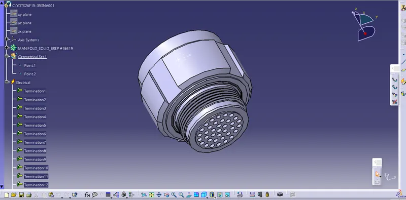

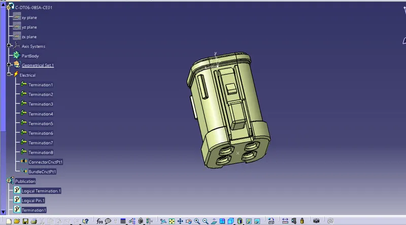
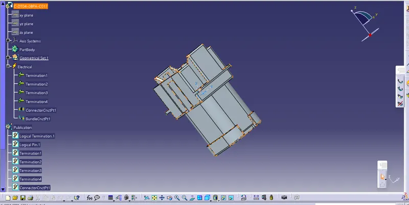
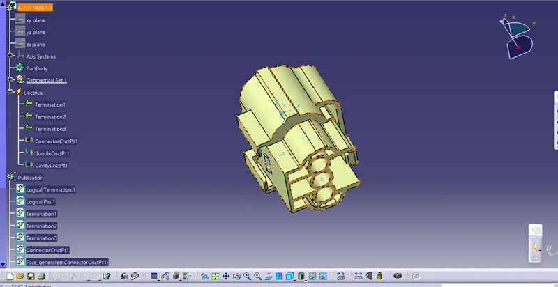
HARNESS B CONNECTORS
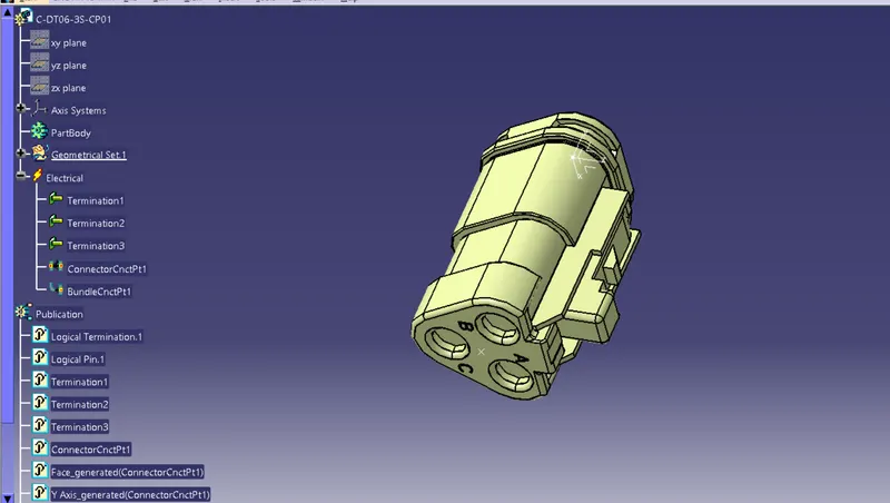
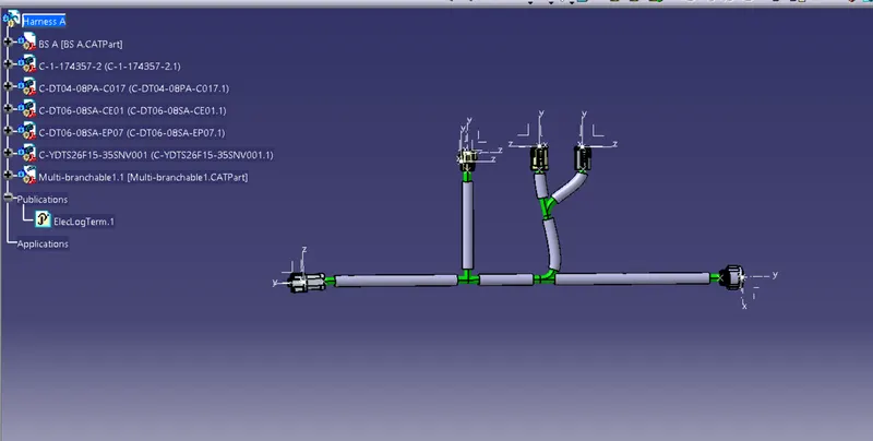
HARNESS A ASSEMBLY
HARNESS B ASSEMBLY
Entire Wiring Assembly with Annotations.
Annotations
Creating the annotation
Switch to the assembly design workbench.
Make sure the geometrical bundle is active.
Select the front view/ annotation plane icon
Select the plane you wish to use for the annotation.
Select the flag note with lader icon
Select a reference point on the part you wish to add the annotation to.
Input the connector function (unit name) in the name definition.
Select OK.
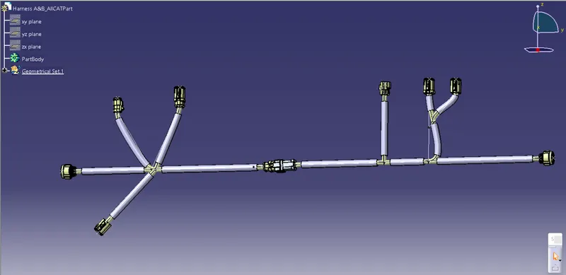
CATpart of Entire Wiring Assembly.
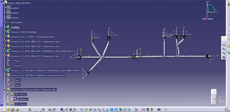
Creating a CAT part from Harness Product Assembly.
This CATpart can be then converted as IGES or STEP
Go to Mechanical Assembly Workbench > Tools > Generate CATPart from Product.
IGS format of Entire Wiring Assembly.
Updating the context assembly and all sub assemblies.
Sometimes, changes wont be applied or Regenerated without updating entire assembly
Activate the context assembly. (Ensure that all surrounding data from other departments is deleted from the context assembly).
If the context assembly requires an update then you will see that the update all icon from
the Catia workbench is available. (Not grayed out).
Select the update all icon.
The context assembly should now be all updated.