Project 2
Question:-
Conduct the post processing of the results once the analysis is complete. The first task includes, checking the base pressure and settlement beneath the base slab which should be within the limits mentioned in Project-1. If these limits are exceeded then the dimensions need to be increased or decreased so that the base pressure and settlement is under control.
Once the foundation is checked, report the following results in order to carry out the structural design of elements.
- Design Maximum and Minimum Moments in walls and base slabs (Wood Armer Simplified Method)
- Design Maximum and Minimum Shear Stresses in walls and base slabs
- Design Maximum and Minimum Axial Stresses in walls and base slabs
Once the post processing of results is done, carry out structural design of the elements by conducting the following checks
- Construct an excel spreadsheet for calculating the reinforcement requirement in short and long walls and base slabs. For calculating the required design reinforcement, the contribution due to direct tension also needs to be added if significant and it can be calculated by adopting the following method (discussed in Week-3):
M,net = M – T . x
Ast1 = (0.5 fck / fy) {1-√[1-(4.6 B.M./(fck.b.d²))]}
Ast2 = T / 0.87 fy
Total Ast, req = Ast1 + Ast2
M = Design moment obtained from Wood Armer equations
T = Design Tension force in the section (Stress x c/s area of FE element)
x = distance of tension reinforcement from the center line of the section
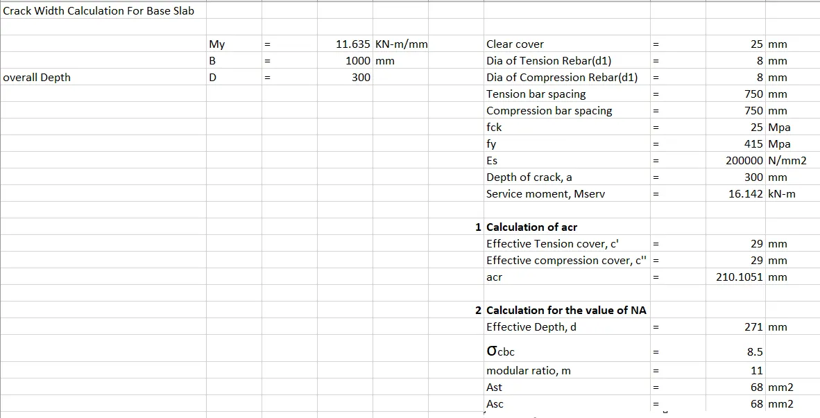
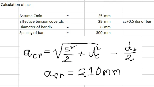
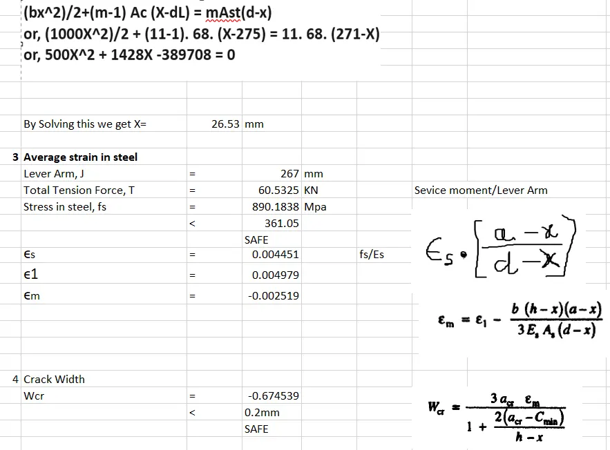
- Check crack widths of short and long walls and base slab and ensure that it is less than 0.2mm.
- Draft cross-sectional reinforcement detail (plan and elevation) using a CAD software. If CAD is not available, sketch the details using any drawing tool and clearly indicate all the details.
Ans=
Open Project-1 Staad file
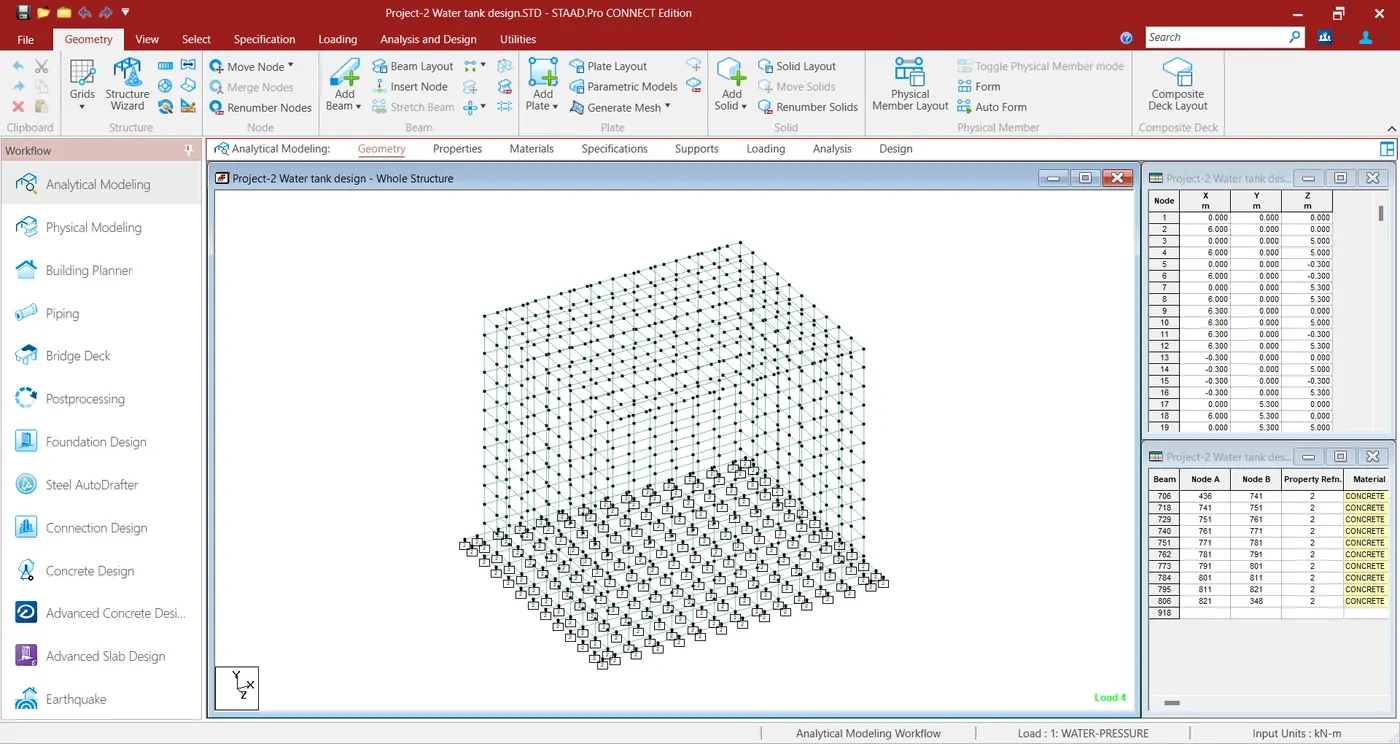
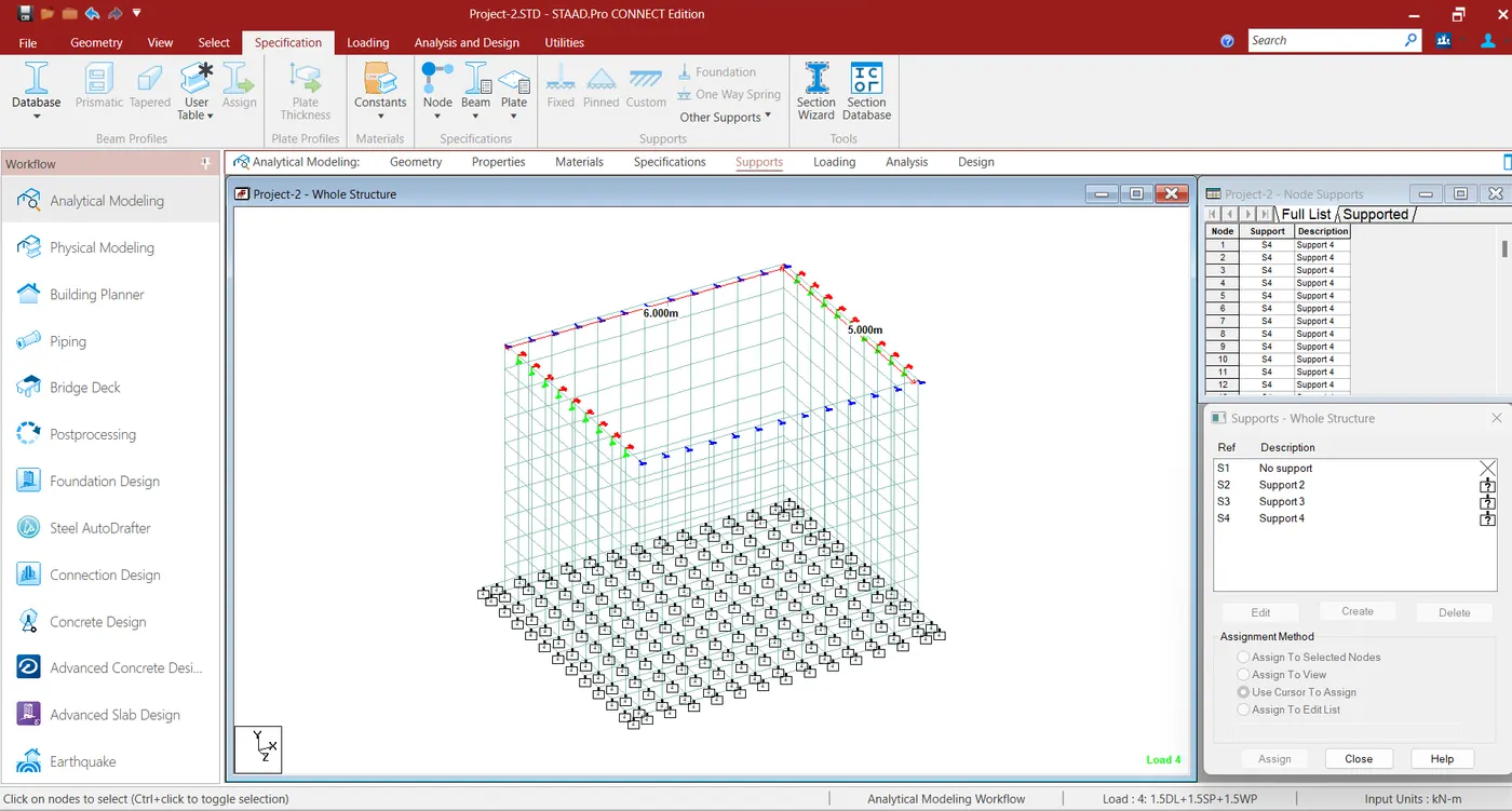
Now I have assigned top supports by releasing x side and z side for short and long walls
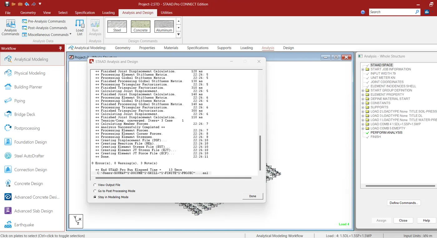
Then I have analysed the structure
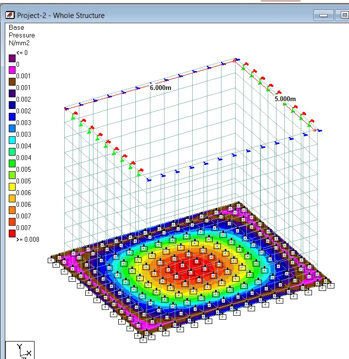
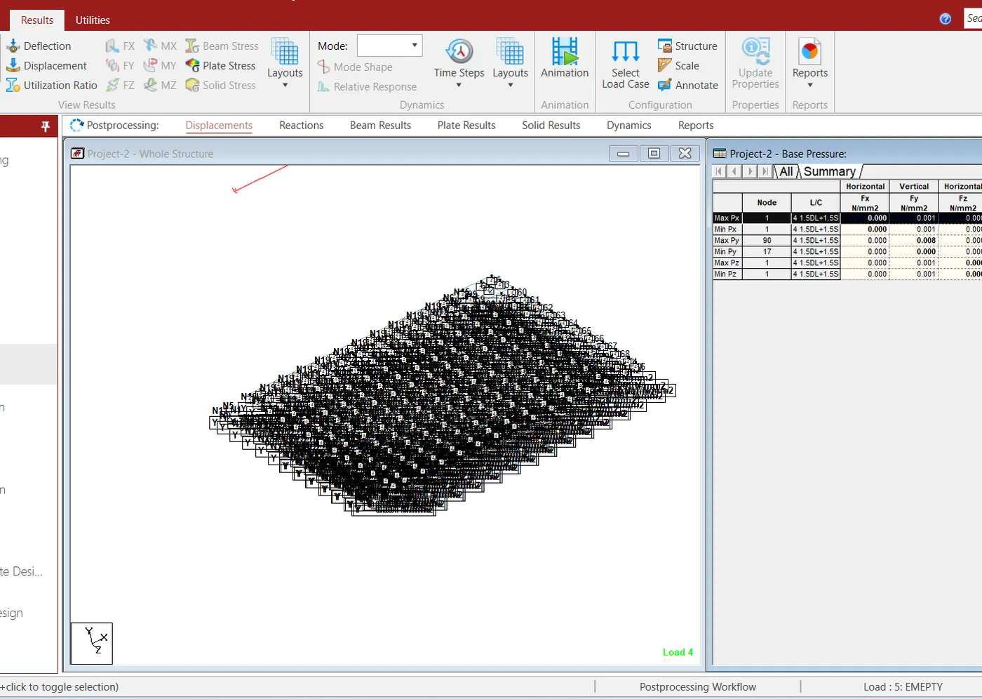
NOW, after analysis I have found base pressure as Fy=0.008 N/mm2 or 8 KN/m2, which is very less than allowable soil bearing capacity of 200 KN/m2
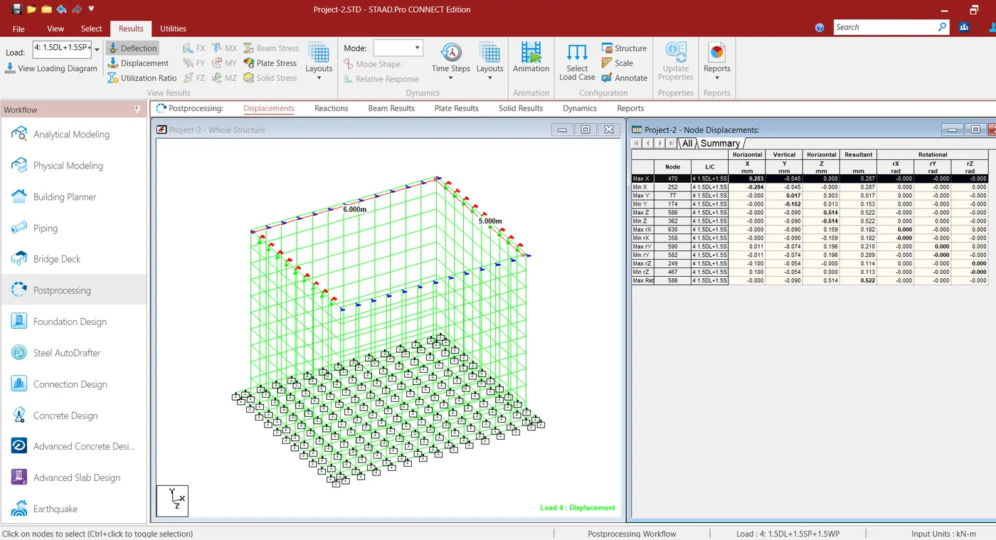
Now maximum allowable settlement is 50mm and here is only 0.514mm deflection, that means it is very safe
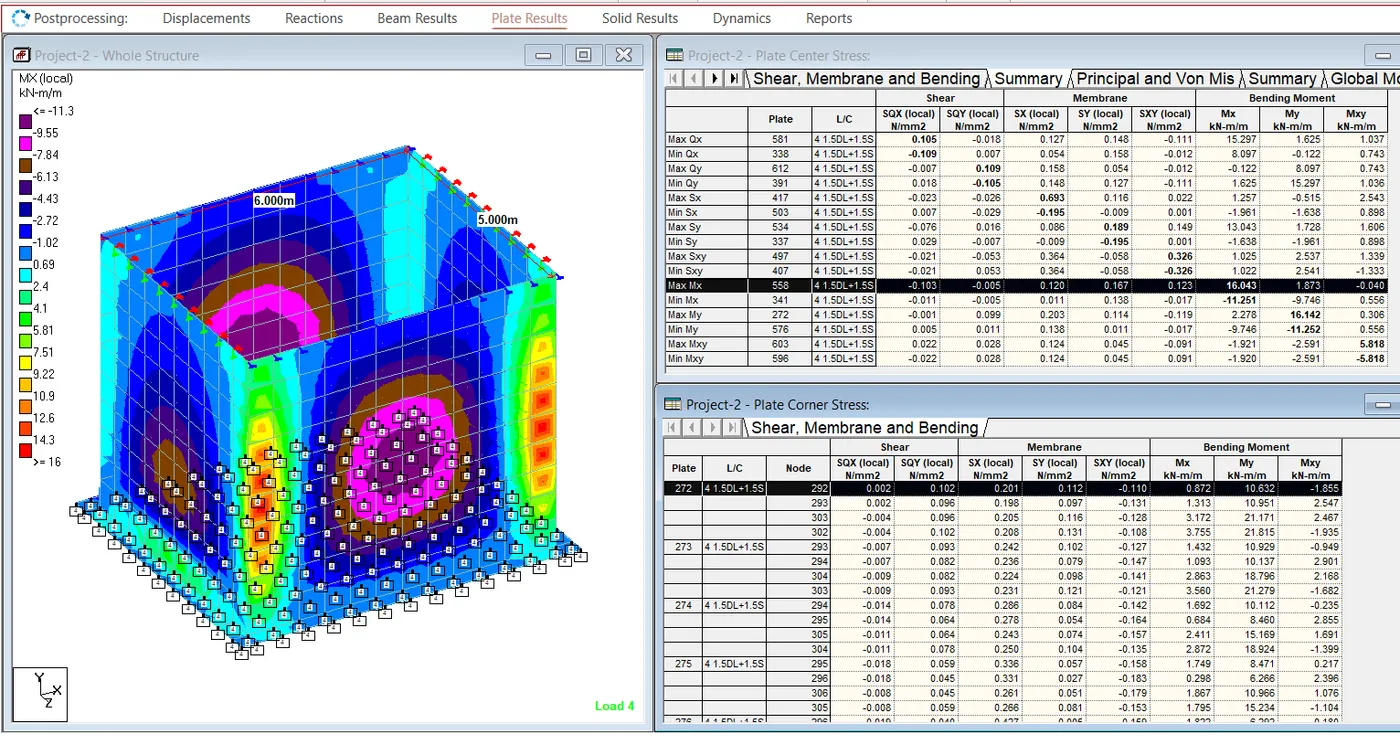
- Design Maximum and Minimum Moments in walls and base slabs (Wood Armer Simplified Method)
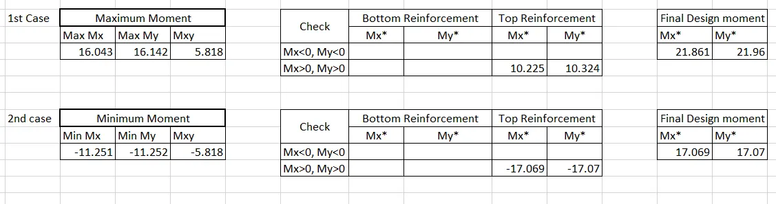
Now I will calculate maximum and minimum moments in wall & base slab (Wood Armer equation)
- Design Maximum and Minimum Shear Stresses in walls and base slabs
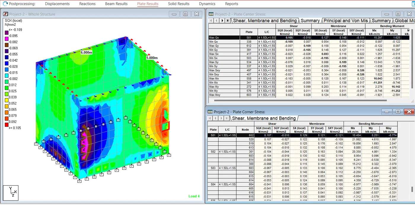
Hence for walls Maximum Shear stress (SQX) is 0.105 N/mm2 and SQY is 0.109 N/mm2
Minimum Shear stress is -0.105 N/mm2
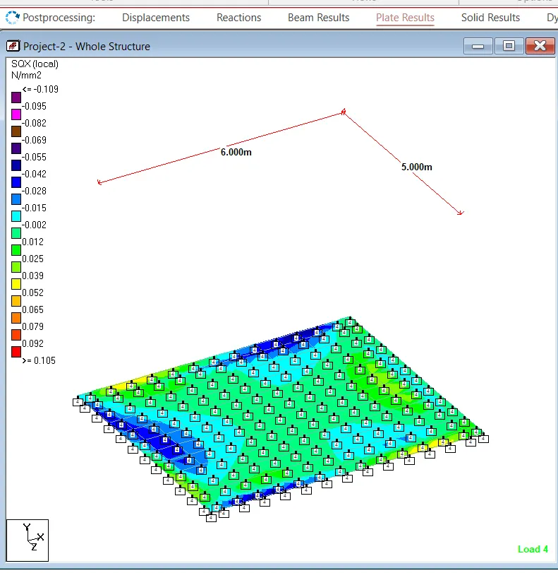
Hence for bottom base slab maximum Shear stress is 0.052 N/mm2 and minimum shear stress is -0.055 N/mm2
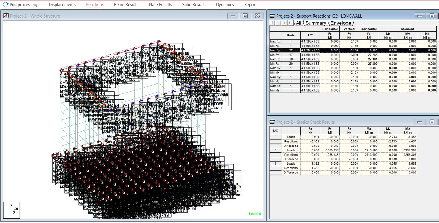
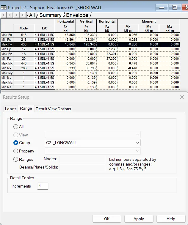
- Design Maximum and Minimum Axial Stresses in walls and base slabs
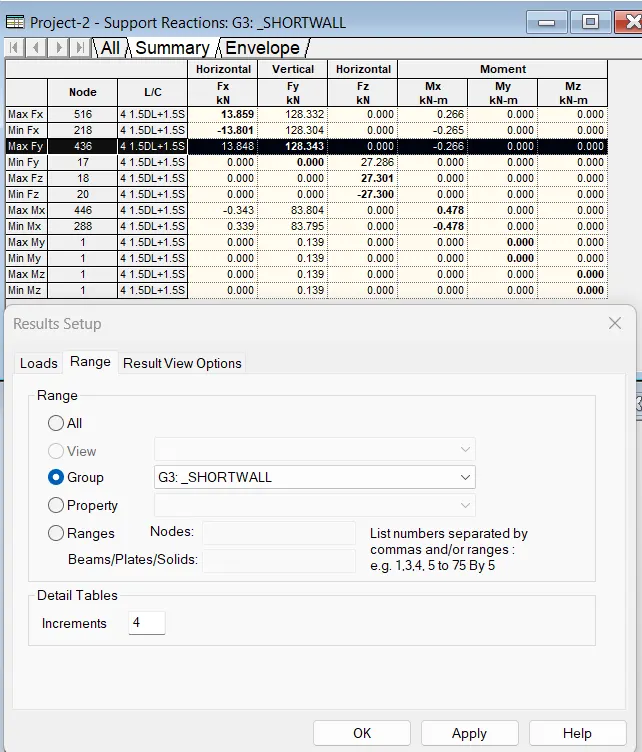
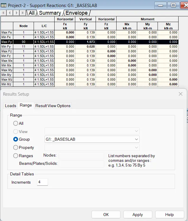
Once the post processing of results is done, carry out structural design of the elements by conducting the following checks
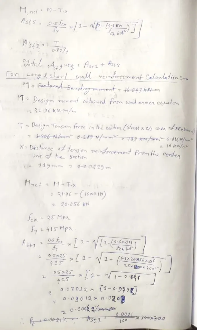
- Construct an excel spreadsheet for calculating the reinforcement requirement in short and long walls and base slabs. For calculating the required design reinforcement, the contribution due to direct tension also needs to be added if significant and it can be calculated by adopting the following method (discussed in Week-3):
M,net = M – T . x
Ast1 = (0.5 fck / fy) {1-√[1-(4.6 B.M./(fck.b.d²))]}
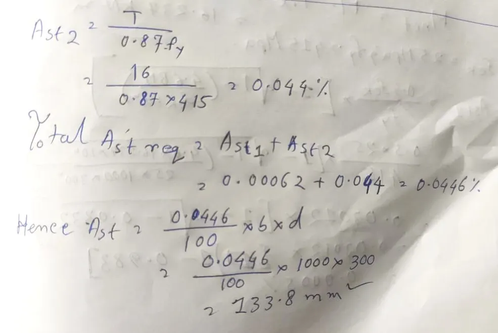
Ast2 = T / 0.87 fy
Total Ast, req = Ast1 + Ast2
M = Design moment obtained from Wood Armer equations
T = Design Tension force in the section (Stress x c/s area of FE element)
x = distance of tension reinforcement from the center line of the section
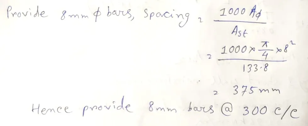
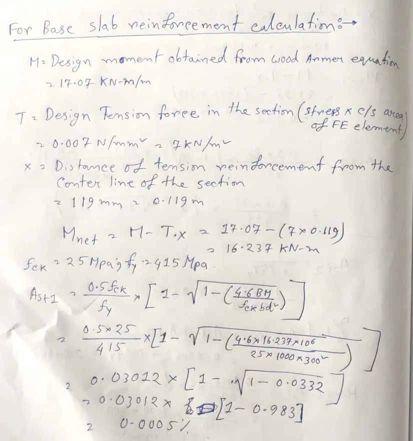
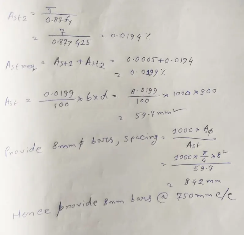
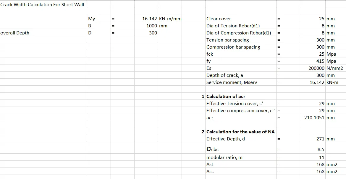
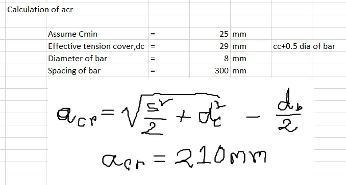
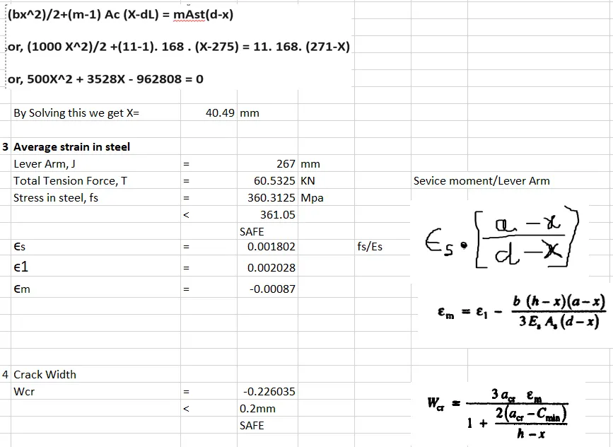
Check crack widths of short and long walls and base slab and ensure that it is less than 0.2mm:-
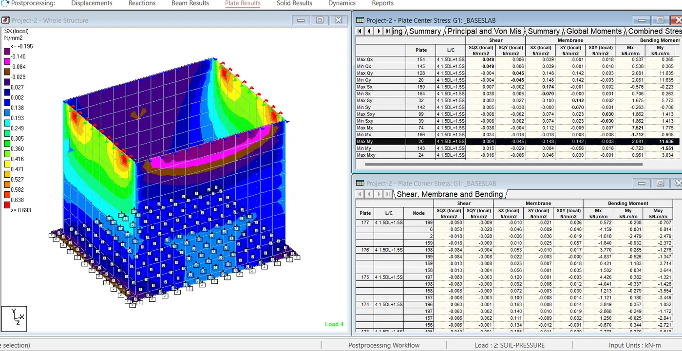
Short & long wall Stress
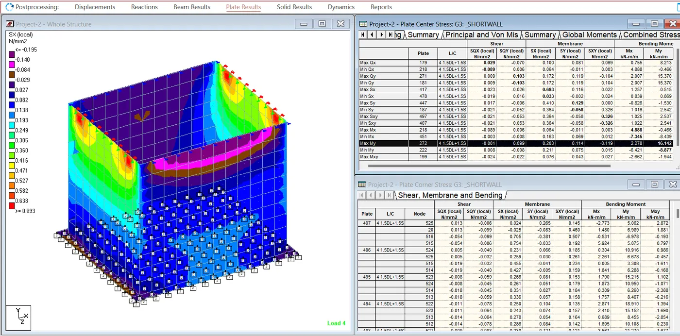
Crack Width calculation
Base Slab Stress
- Draft cross-sectional reinforcement detail (plan and elevation) using a CAD software. If CAD is not available, sketch the details using any drawing tool and clearly indicate all the details.
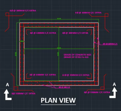
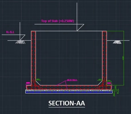
Final Result:-
I have attached final Staad.pro file, wood armer equation calcution excel sheet, Crack width calculation Excel sheet and pdf file of final plan and elevation drawing, Also CAD file of drawing for further reference.