Project 2
AIM: Route the Wiring harness on Given car body and Prepare flatten view drawing in CATIA V5.
Step 1: Study the given CAD Model.
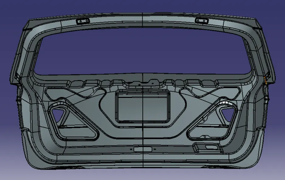
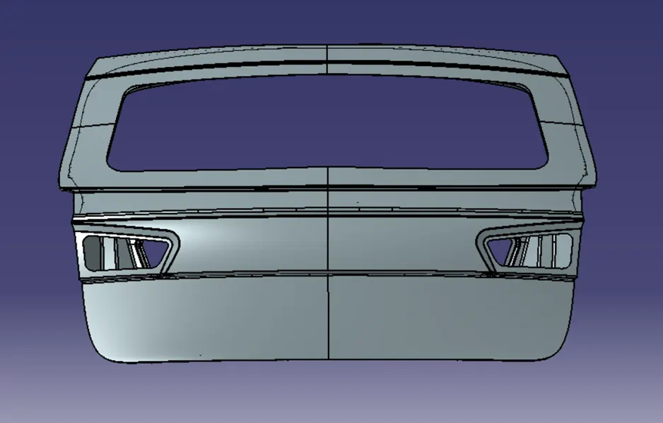
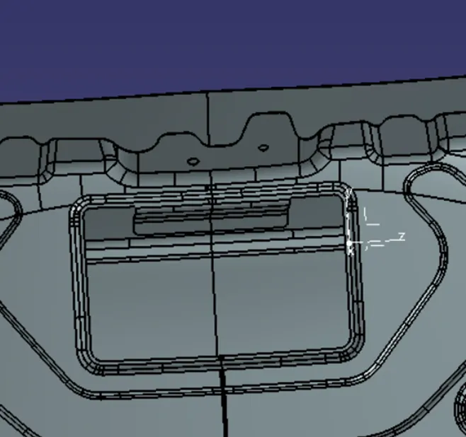
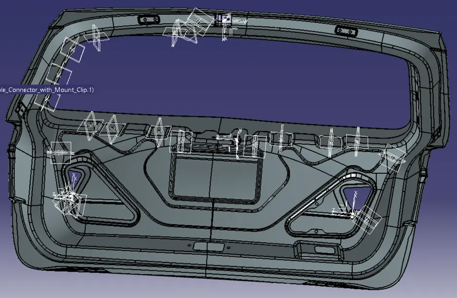
The input CAD model is that of a rear door of a car. From analyzing the model it can be observed that the model accommodates space for the mounting of headlights on either sides at its bottom. It also has space to accommodate a rear wiper, so accordingly a harness cable should be used to connect for the wiper motor. So a virtual layout of the wiring harness is conceptualized in accordance with the design of the back door panel and the necessary connectors and other wiring harness components are selected.
Step 2: Defining the harness components Electrically.
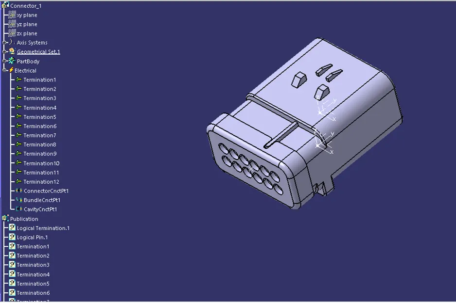
All the components to be used for the routing are first defined electrically in the ‘Electrical Part Design’ workbench and then saved in a suitable catalogue. A 12 pole interconnection connector is chosen from which the routing is branched out to connect to the two headlights and the wiper motor using 3 pole connectors.
<!-- [if !supportLists]-->1. <!--[endif]-->Interconnection Connector:
<!-- [if !supportLists]-->2. <!--[endif]-->3-Pole Connector
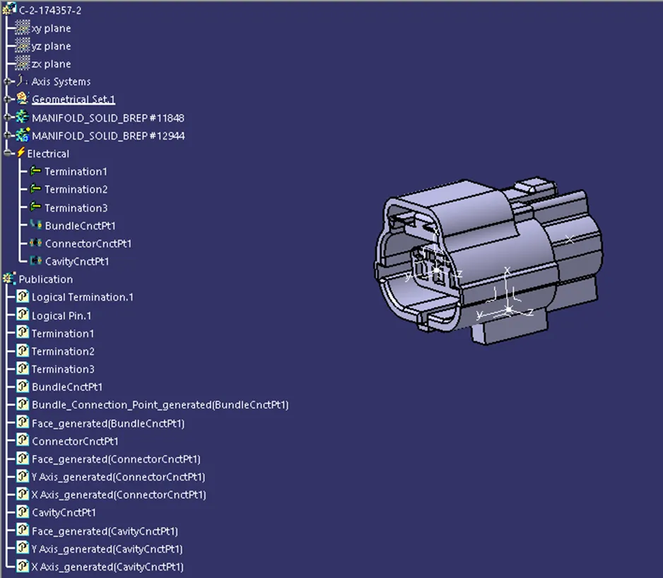
<!-- [if !supportLists]-->3. <!--[endif]-->3-Pole Connector with Mounting Clip<!--[endif]-->
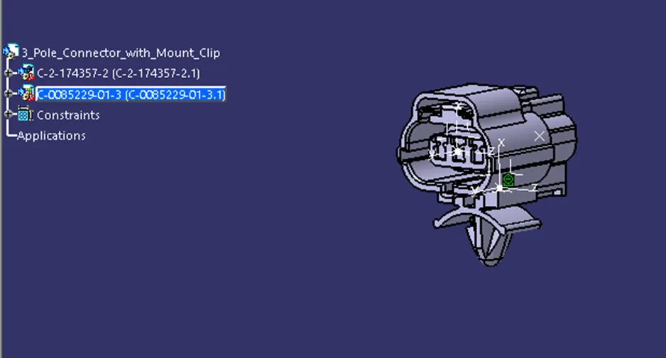
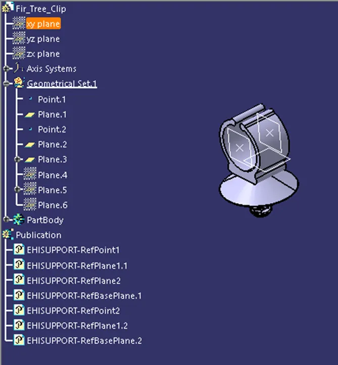
<!-- [if !supportLists]-->4. <!--[endif]-->Fir Tree Clip
<!--[endif]-->
Step 3: Create a Wiring harness context assembly product
To start with the routing process, a context assembly product file is created into which the support CAD product file of the back door and a Harness routing product file are inserted. Then into the Harness routing product file, all the electrically defined routing components are inserted and are placed at their respective positions in accordance with the reference back door model using various manipulation commands in the ‘Assembly Design’ workbench.
Step 4: Create routing bundle connecting all components.
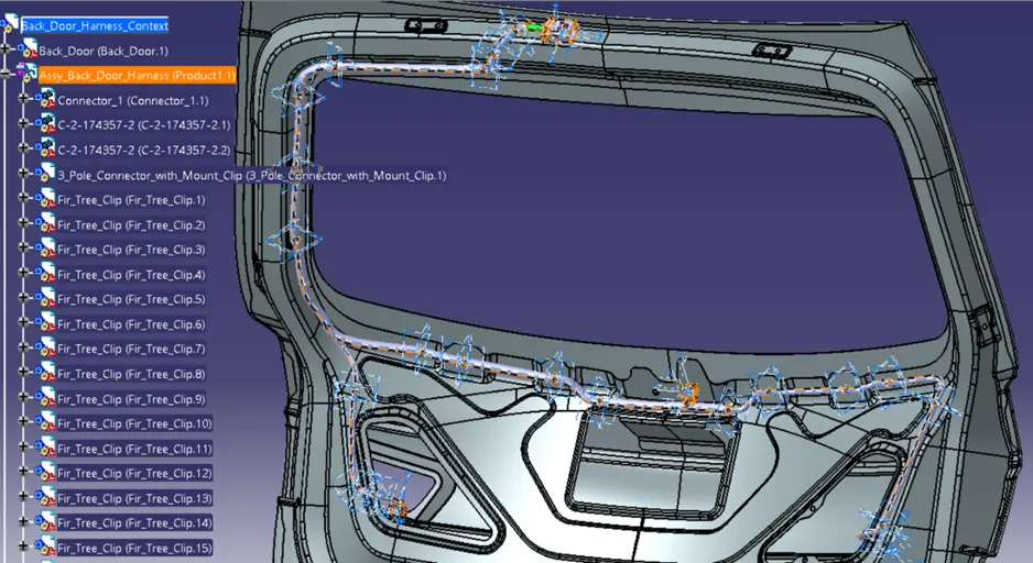
Go to the ‘Wiring Harness Assembly’ workbench and then electrify the ‘Assy_Back_Door_Harness product file using the ‘Geometrical Bundle’ command. Then using the ‘Multi-Branchable Document’ command start routing the bundle segment connecting the components using suitable properties and bend ratio. Provide protection covering to the bundle segment if necessary to obtain the harness routing for the system. Then save the file.
<!--[endif]-->
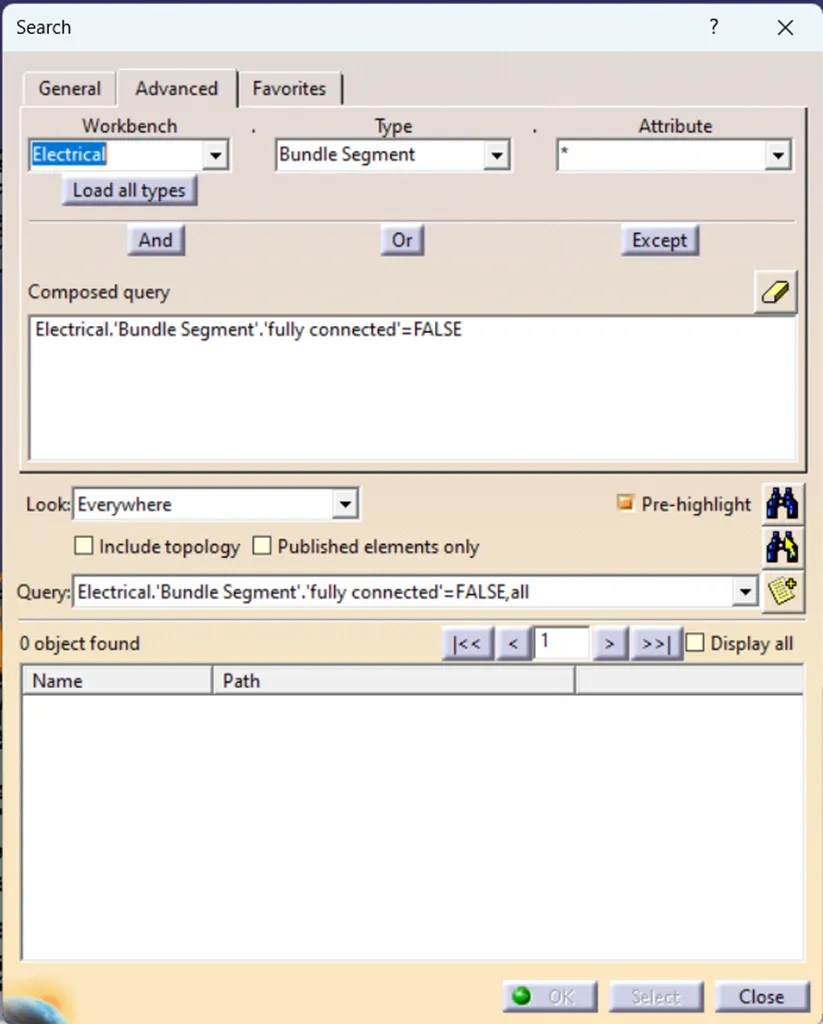
Step 5: Check for the bundle continuity.
<!--[endif]-->
Step 6: Flattening the wiring harness assembly
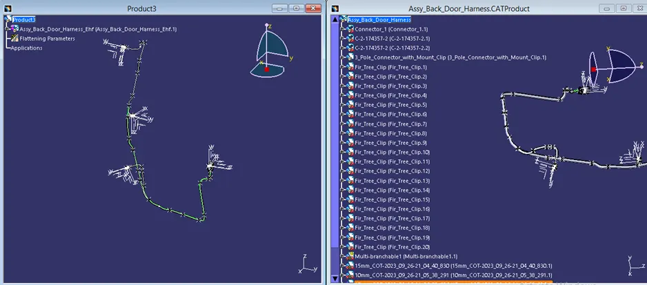
To flatten the wiring harness assembly, first create a new flattening product file and set the flattening parameters for the document. Then extract the 3D harness into the product file from the original harness assembly using ‘Extract’ command in the ‘Wiring Harness Flattening’ workbench. Use ‘Flatten’ command and select a suitable plane, then select all the bundles and click ‘ok’. The bundle assembly will automatically flatten in the selected plane and if necessary reorient the component using various manipulation commands. Finally synchronize the flattened harness assembly and save the file.
<!--[endif]-->
<!--[endif]-->
Step 7: Create 2D Drawing
To create a 2D drawing of the harness assembly, first create a new drawing file and select a suitable plane about which the drawing needs to be created. Reorient the drawing in required orientation and scale to fit in the selected page properties and change the drawing properties to view the harness layout properly.
<!--[endif]-->