Project 2
AIM :-
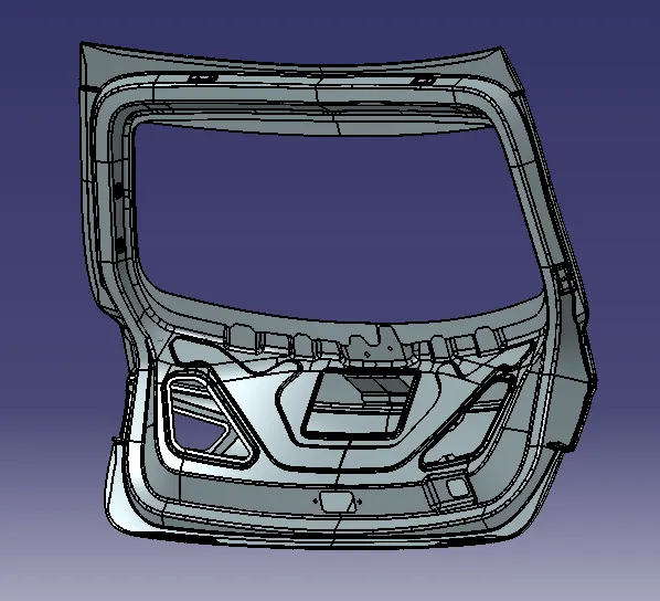
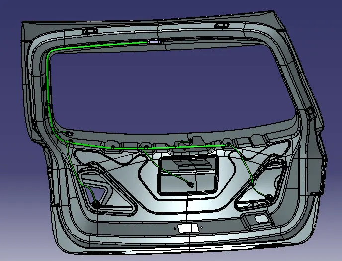
Here we need to Route the Wiring harness on Given Back Door_Trim of a car and Prepare flatten view drawing in CATIA V5. Application of all Packaging rules, Industry best practices studied in this course shall be demonstrated in design. Need to Apply Protection coverings as required.
ABSTRACT :-
Route the Wiring harness on Given car body and Prepare flatten view drawing in CATIA V5. Application of all Packaging rules, Industry best practices studied in this course shall be demonstrated in design. Apply Protection coverings as required.
Available connector 3D data can be used, or you can download the connectors from WWW.TE.COM
Prepare & Submit all necessary reports like clearance, Clipping/Clamping selection, Harness fixing requirements, Harness continuity, Assumptions if any along with CATIA 3D data.
SOLUTION :-
First we need to download the Back_Doortrim step file that is provided same lynk. Also the CAD data to be provided we need to downloa it. or also we can ue a 2nd option is TE.com for the products & necessary componets.
For the complete solution of a Back Doortrim wiring harness the Procedure we have followed as :
PROCEDURE_1 :- Downloaded Required data convert into Electical/ Define it electrically./ Creating Context Assembly
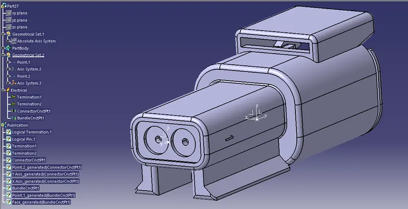
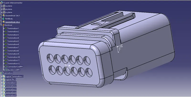
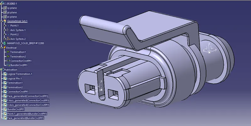
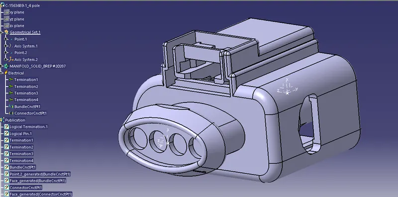
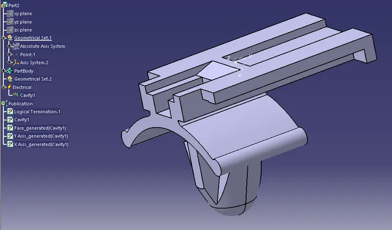
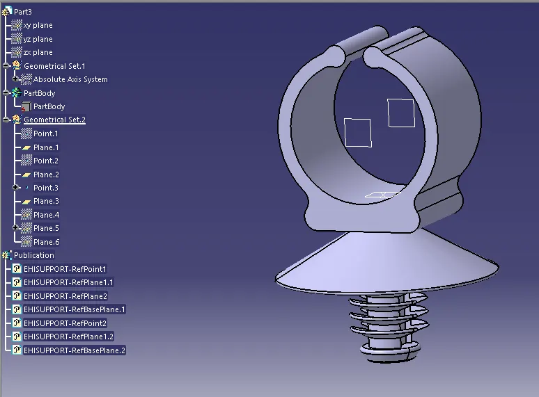
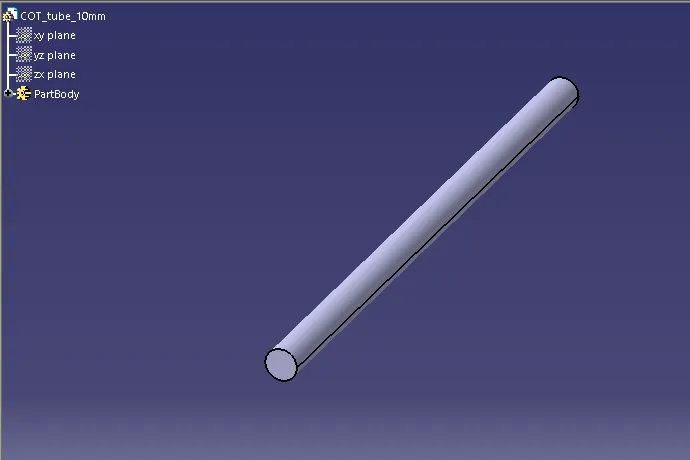
Finally define all the components as electrically & store them into each a seperate calatogue documents as well.
PROCEDURE_2 :- Placing the all Connector at desired location
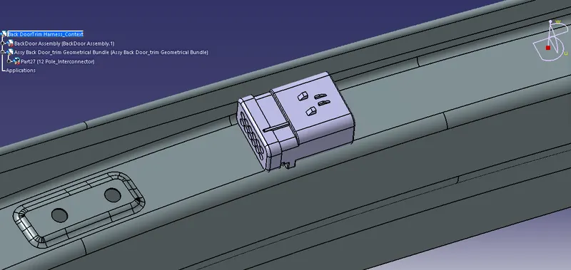
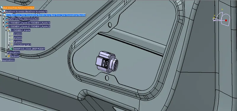
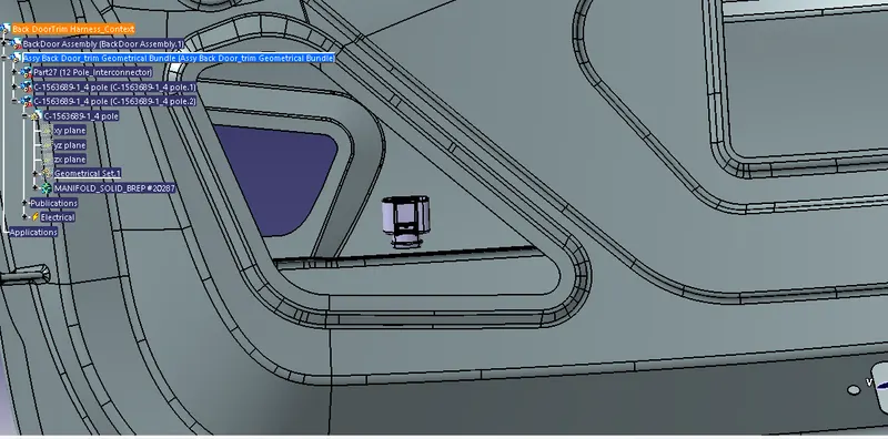
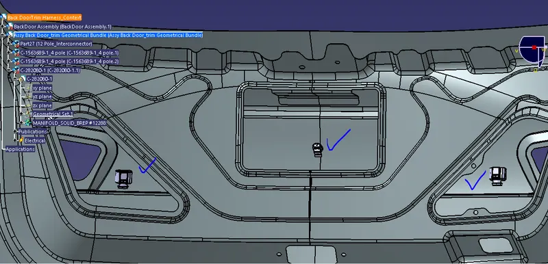
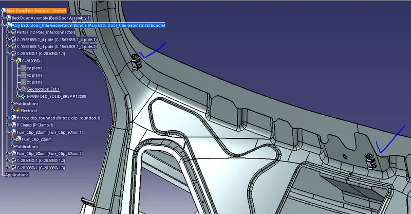
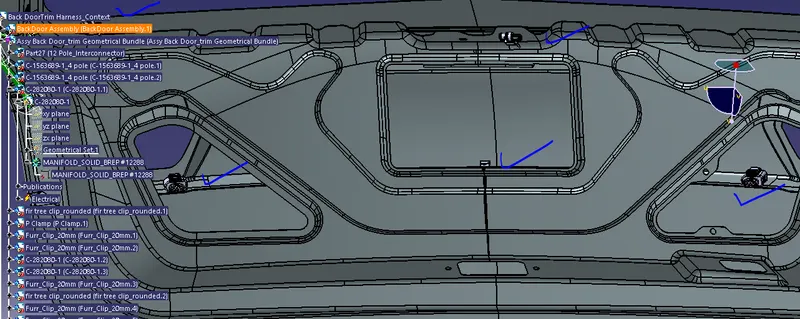
From the above snap noted as , we have a Doortrim & we need to place the Connector , P_clamp clip, Fir tree-clip, at a desired location where we route the bundle.
In this Back Doortrim There are mainly 4 type of sensor in a whole circuit as follows:
A] Brake light sensor :- we place the 2 at left side & another right side of a doortrim, that is 4 pole connector are place there.
Role :- The main function of a Brake lights serve an important function as they warn the driver behind that your vehicle is slowing down. Off-road vehicles driving on public roads must be equipped with a brake light system according to the road rules.
B] Number plate light sensor :- The 2 pole connector are place near to the number plate.
Role :-The function of a number plate lifht is to show the Regester number of a R.T.O. rules of a vehicle specific at the clear seen at the night mode.
C] Rear wiper motor sensor :-2 pole connector required to place at the wiper motor senser.
Role :- For the clean visibility & avoid the mist, water over the backDoor glass, cleanning & swipe out the water easily from the glass window.
D] Defogger connection sensor :- 2 pole connector is place there.
Role :-A defogger, demister, or defroster is a system to clear condensation and thaw frost from the windshield, backglass, or side windows of a motor vehicle.Windshield defrosters blow air from the heating and ventilation system onto the windshield through vents at the forward edge of the dashboard. Most vehicles have a setting for directing all air to the windshield for maximum defrosting or splitting the air between the windshield and floor level.04-Jul-2021
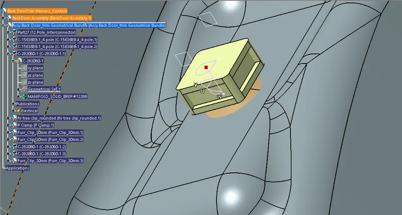
PROCEDURE_3 :- Placing the fir tree clip.
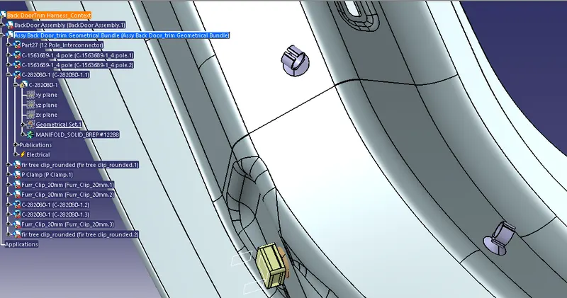
PROCEDURE_4 :- Placing the p_Clamp & fir tree clip rounded at required position.
PROCEDURE_5 :- ROUTE THE BOUNDLE
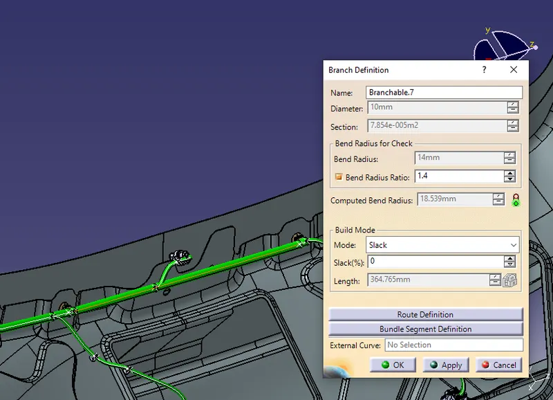
- For routing the bundle first we need to switch the current workbench into Electical Harness assembly & select a multi-brancable command.
- After we need to active the assy harness bundle & select a branch defination to route the bundle.
- The initial starting point of a bundle is a inerconnector, From which the whole rounting is done to complete doortrim harness.
- So the first main bundle diameter is takes as a 10mm & For the sub_brach 7mm or 5 mm take.
- Just like from interconnector to final connector with guide & suppport taken as clips we route a bundle as well.
PROCEDURE_6:- Apply a protection covering Over the bundle.
The protection cover should be a cot tubes, cotton tape or sleeves are applied over the bundle for the protection againt the heat, fire, avoid the chipping with sharp edges of a sheet parts, & to avoid the corrosion. Here we use a Cot_tubes that are created and stored in a Cot_tubes Catalogue as well. We have applied mainly the 5mm & 10mm Cot tube over the bundle at different sub_branch as well.
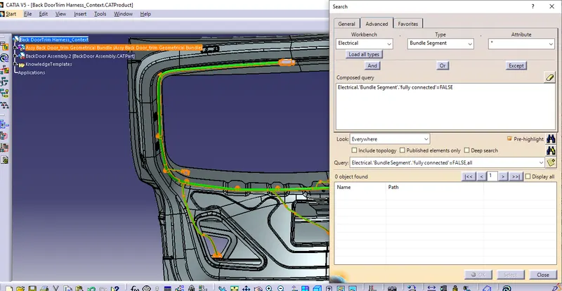
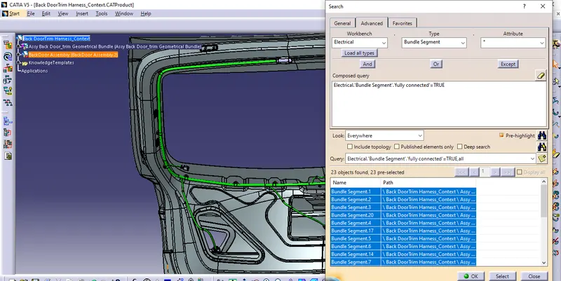
PROCEDURE_7 :- Check the bundle contunity
After completing the bundle routing we need to check the bundle continuty for the flattening porpose & need to check or fingd out any eror is there.
PROCEDURE_8 :- Flattening the routed engine harness bundle
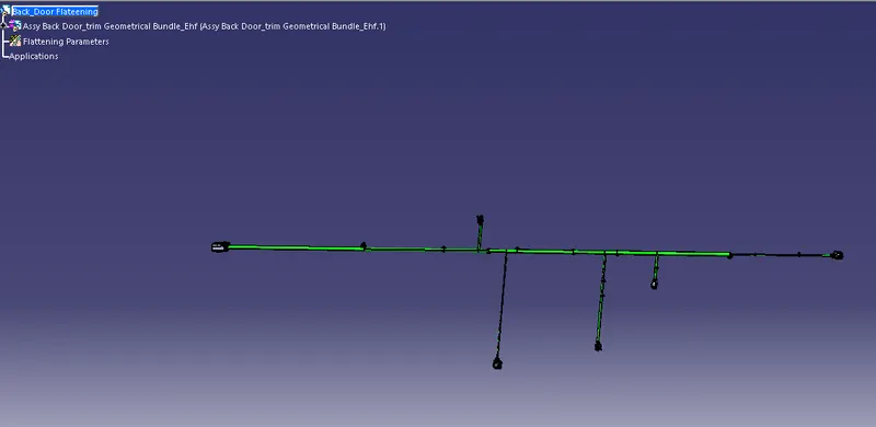
The wiring harness flattening consists of assembly of geometrical bundle to form a flatten bundle to get the 2D drawing details. For the mechanical wiring harness, assembly of geometrical bundle is the main component.
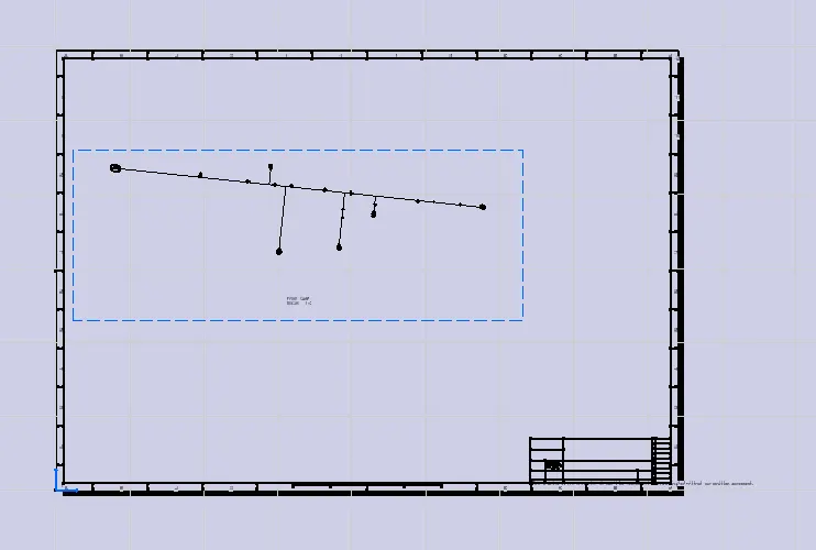
PROCEDURE_9 :- Drafting of a flattened assemly / 2D drawing.
For the creation the drawing we need to create the new drawing and select a front face in the drawing when we tie it vertically we have to selsect front face command in drawing and automatically the drawinng are create by the , parameter has created in the flattening setting. So we need to orinted it properly and creates a drawing with title box.
CONCLUSION :-
In this way we have routed the bundle whole assembly by provided data & design consideration & flatten the Geometrical bundle & finally created the drawing. The neccesary snaps are attached to the report with neat explanation done the over & browe the Zip file to the final requirement.
Thank You.