Wiring harness design in CATIA V5 - 3D modeling Week 5 & 6 Challenge
AIM:-
To Routing the provided harness layout in Electrical workbench. Make an assume for harness bundle diameters, Taken as own 15 & 10 for sub-branch respectively. Using the connectors provided. After completion of routing,
Need to check:-
- Check the bundle Continuity. Add snap of result in submission
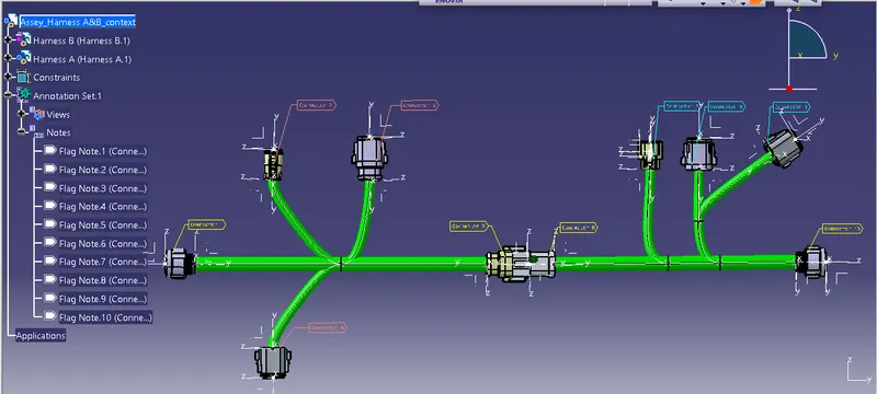
- Add annotation to all connectors. Make an assumptions for annotations like connect 1 , 2 etc
- Check for the bundle warning. Add snap.
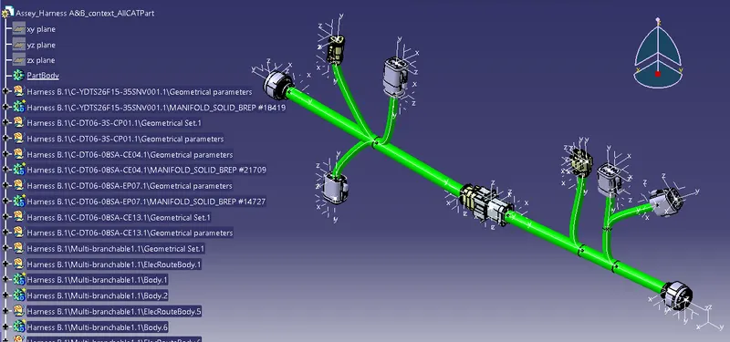
- Generate CAT.part of harness assembly and convert is in. igs format.
1st, Procedure :-
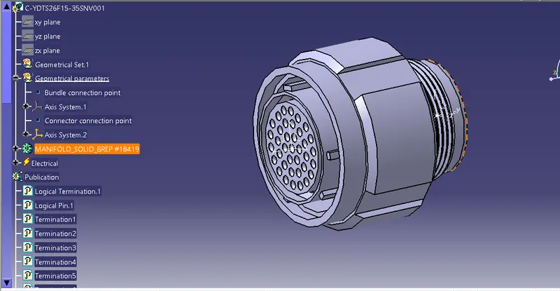
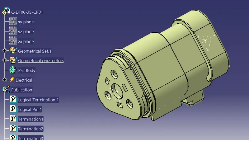
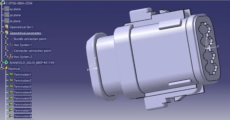
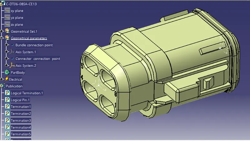
From the link provided cad_data files of the connectors has downloded & maked as an cad part. After that maked it is an Electrical part with provided all geometrical features.
1] For the harness B , The electrically define connectors as follows.
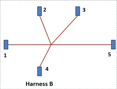
2] Path layout of Harness B
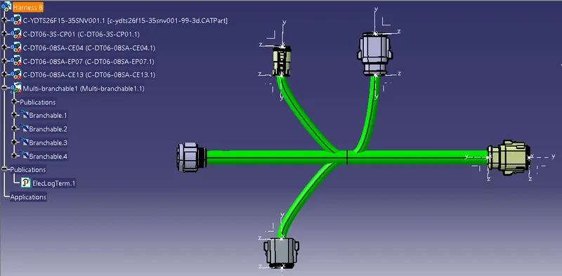
- Actual wiring harness of the Harness B
- Firstly created the new product file.
- Then added all required connectors by the command adding a new existing component in a created Harness B product file.
- Switch the part design into the assembly workbench amd arranged the connectors by using the tool command as Manipulation, compass, snap & Smart move.
- Again switched the part assembly design into the electrical harness assembly workbench, And firstly define the product file of a harness b as a Geometrical bundle.
- Click the command multi branchable and provided the 15mm Dia to the bundle as a size, with an 1.4 as a bend radius.
- And routed the bundle with first connector and next connector .
- Finally the branched point with again bundle segment routing is done, and the Harness is ready. The snap is attached to the report.
3] Just like wiring Harness B , same all the required connectors are electrically define & provided all necessary geometrical features in its.
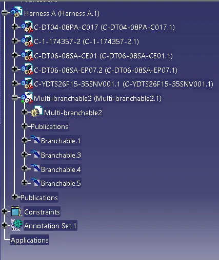
And the routed the Harness A , the snap is attached to the report.
-
Path layout of Harness B
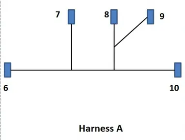
Harness A
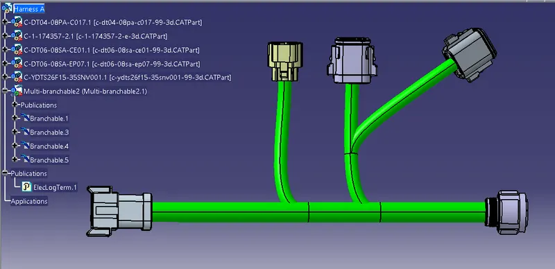
4] Completion of routing Harness A&B
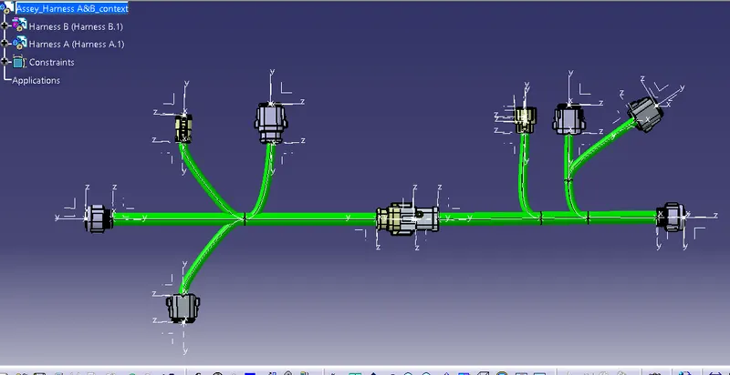
5] following parameters has checked that has needed to the report.
1.Checked here the bundle Continuity. Added snap of result to the report.
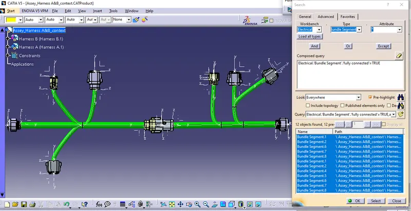
2. Added gives the annotation to all connectors. Maked an assume for annotations like connect 1 , 2 wise.
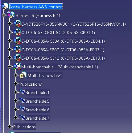
3] Here i Checked the bundle warning & Added snap to report.
4] Generated the CAT.part of harness assembly and converted as well is in. igs format.
Conclusion :-
- In this way the routing Harness A&B has created by the provided connectors lynk and the mapping data and the path layout.
- All the required task and the neccesary 4 works has done .
- The cad file connectors , Electrically define connectors , Routing harness A&B, Cad file & final IGS file has browse/submitted as well.
Thank you.