Project 2
CPU FAN BEZEL MOLD DESIGN
Aim:
- To create a complete mold block for CPU fan bezel model.
- To design slider, ejector pins, sprue, runner, gate and cooling channels for the mold blocks.
Procedure:
First import the model in the part file and save the file.
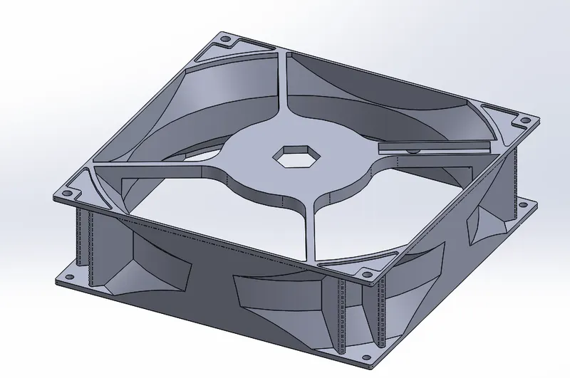
- Check the given part properly.
- Perform a draft analysis to verify the draft angle on each surfaces.
- Click draft analysis command and select the top plane for the reference and enter draft angle as 0.5 degree.
- Click Ok.
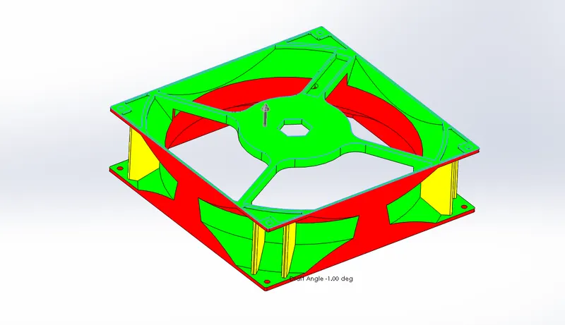
- The draft analysis shows 3 region red, yellow and green region as shown in above figure.
- The yellow region indicates that sufficient draft is not provided to that surface which will impact the performance of the mold block while working.
- This information in transferred to the Product design team such that they can add drafts to the surfaces.
- Here we will be proceeding with the same model as of now.
Parting line creation:
- Increase the scale of the component to 1.006 i.ie., considering the shrinkage of the material is 0.6%
- Next we have to create parting line.
- Draw a line at the front plane and side plane.
- The use split commont to creat a split at the component model as shwin below.
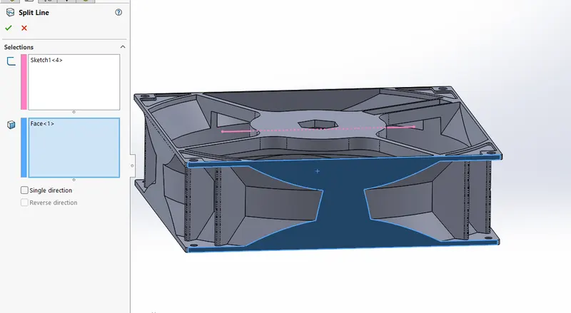
Click parting line option ans select the appropriate edge required to create the parting line.
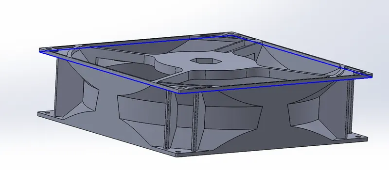
Shut off surface creation:
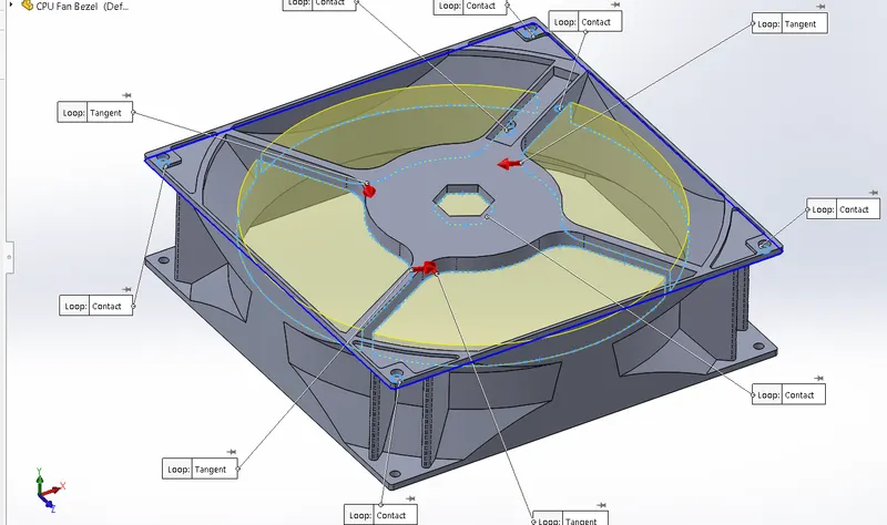
- A shut-off surface closes up a through hole by creating a surface patch along a parting line or edges that form a continuous loop.
- Select the edges as shown in below figure and assign with porper loop condition.
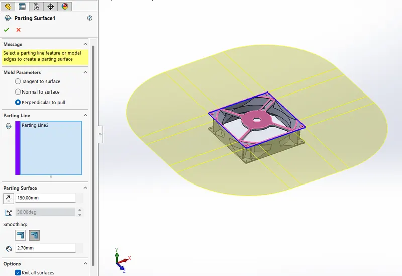
Now using the parting line, create a parting surface as shown below. The length should be 150mm.
- Make a copy of the planar surface.
- Now using knit surface command merge the cavity surface with one planar surface and similarly the other planar surface with core surface.
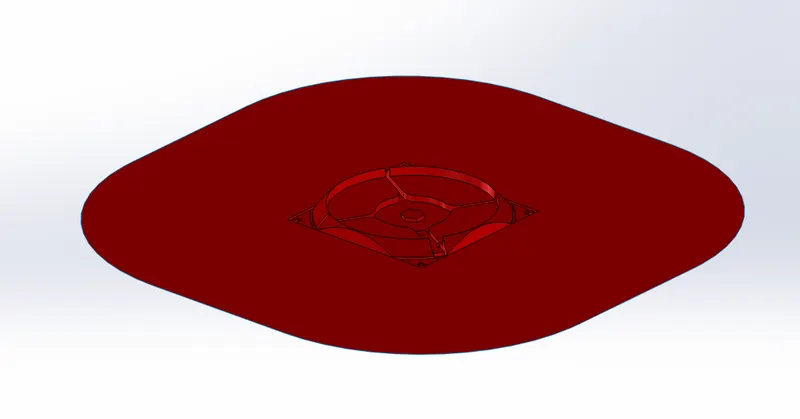
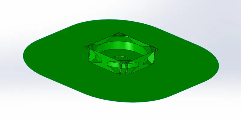
- From here on we will be creating the the core and cavity block in two different part files and merging all in single assembly file.
- Now all the work will be done in assembly workbench.
- Create 2 seperacte part files as shwon below.
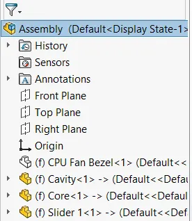
- Adjust the plastic CPU fan bezel component part and match the origin of the assembly to the sprue location as required.
- The mating condition between the right plane of both component and assembly.
- Draw a square at the top surface of the surface and extrude it to 150mm in both the directions.
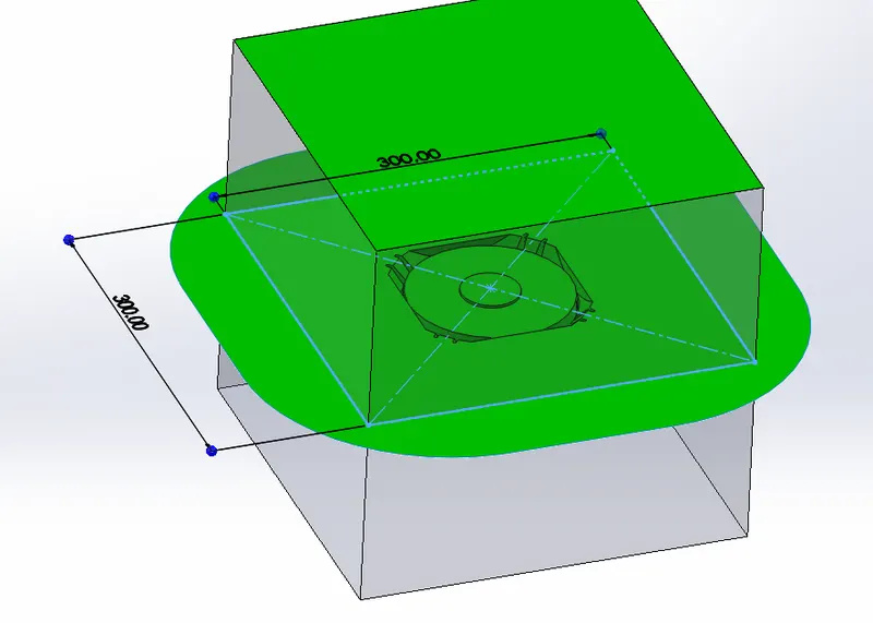
Using surafce cut trim the unwanted region to create the core block as shown below.
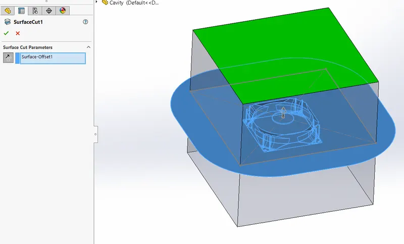
Select the top surface of the core block and draw a sketch as shown in figure below.
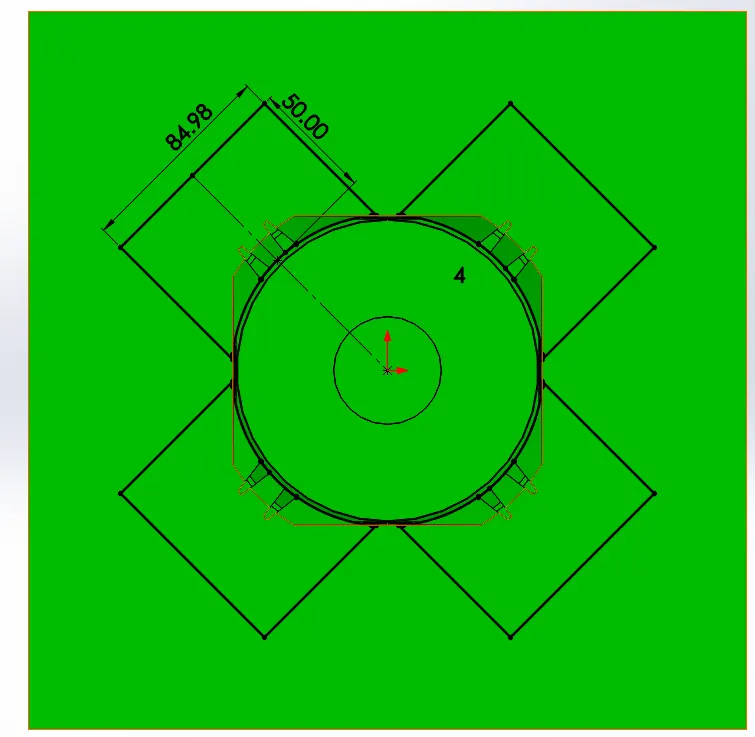
- Create a reference plane to specify the depth of the slider region.
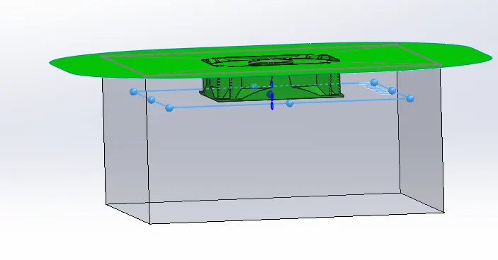
- Using split command cut the core body by selecting the sketch and the reference plane as the trim tools.
- Now select the region which we require to split up as shown below.
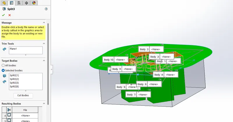
- Change the colour of the split block to yellow.
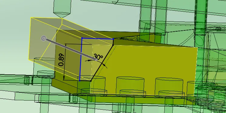
- Draw a sketch for the wedge creation. The angle should be 30 degrees and using extrude cure remove the material.
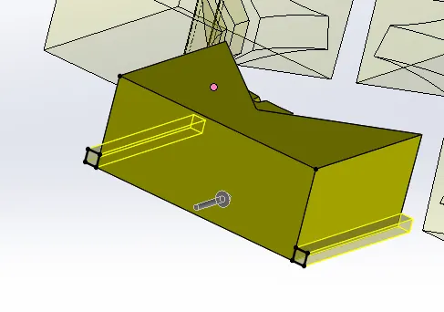
- Again draw to rectange oth 5mm with on either side of the bottom surface of the slide.
- Now save the slider part in a seperate parasolid file.
- Create a new part file in the assembly and rename the file as slider.
- Import the saved parasolid file and save it.
- Again edit the core block.
- Using combine option subtract the slider component from the core block.
- Next we have to create the collar space for the bolt fixing.
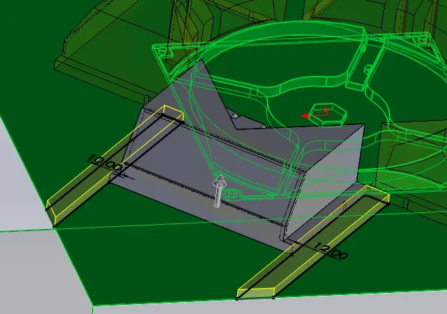
- Draw the rectangle of with 15mm from the edge of the slider collar and cut using cut extrude command till the upper surface of the clore block.
- Now the core block block is completed.
- Edit the cavity block.
- Import the parasolid file and subtract using combine command as shown below.
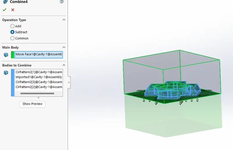
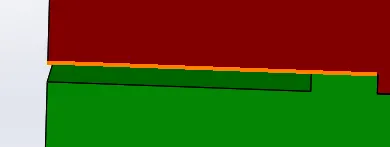
- We can observe from the below image that there is a contact between the vertical surfaces of the core and the cavity block.
- This may lead to the wear / damage to the surfaces of the block.
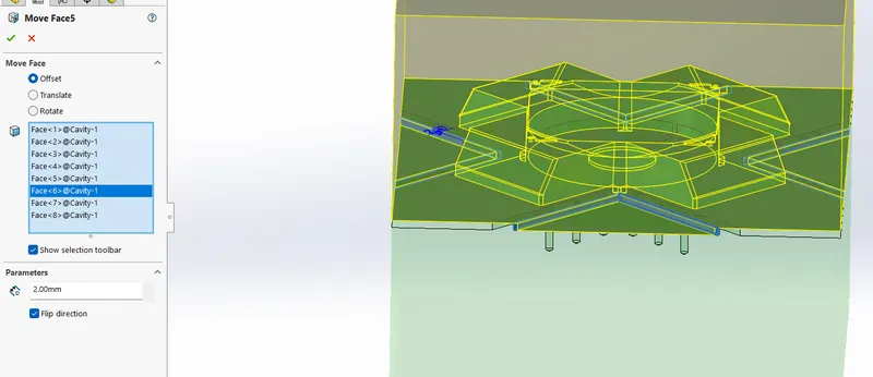
Offset the faces of the core block as shown below using move face command upto 2mm distance as shown below.
Next we have to create washers and bolts for the fixment of the slider.
Create new part file and draw a circular sketch as shwon below and extrude to 3mm.
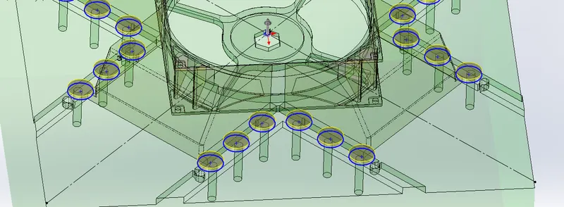
These is the washers and change the colour to grey to distinguisd between the washer and bolts.
Similarly create the bolts and make sure that the merge entites is deselect.
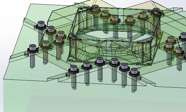
Next we have to create the ejector pins at appropriate location for easy removal of the component from the mold block.
In order to create the ejector pins, create a sketch on the top surface of the cavity block as shown below,
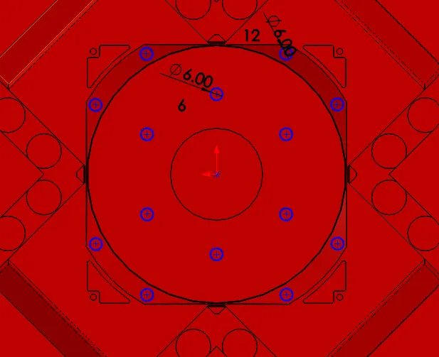
Create a ejector pins with above sketch using core command.
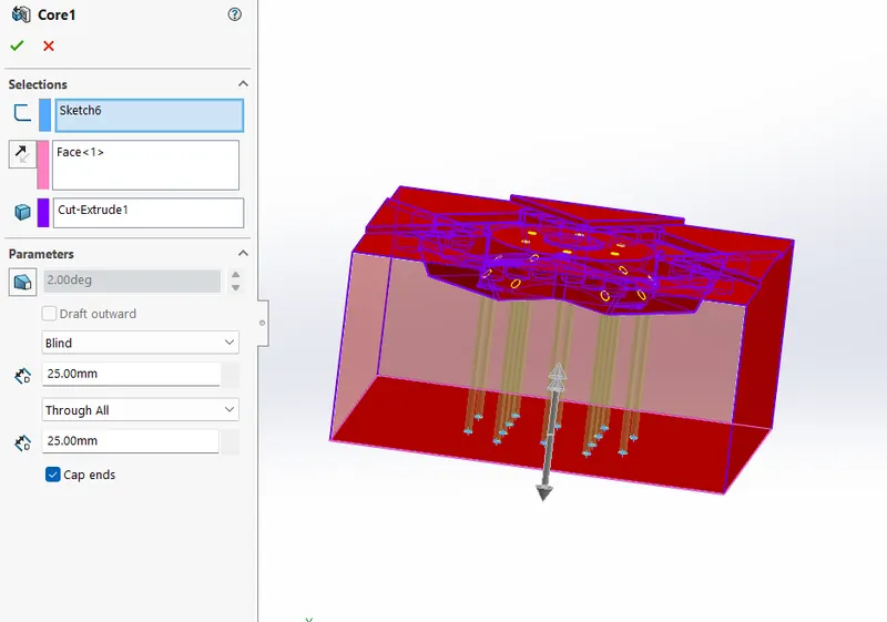
Create ejector pins of 6mm diameter using boss extrude command.
Select offset of about 250mm from the bottom surface.
Create a clearance hole of aprrox. 6.96mm diameter.
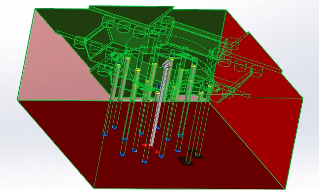
Next we wil be creating the ejector plates. Before that we will be creating the head portion of the ejector pins.
Draw a cirlces on the top surface of the pin of diameter 10mm cut partially for locking purpose and extrude for about 3mm upward.
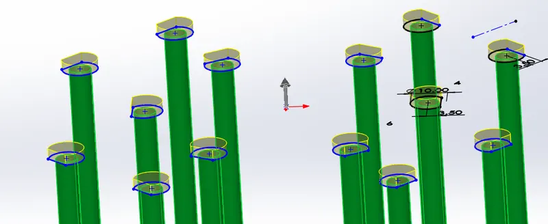
Draw a rectangle on the top surface of the pin head and extrude for about 10mm downward and anandeselect merge entities.
The 2 side of the rectangle sectionhould at an offset distance of 45mm from the side of the mold block inwards direction.
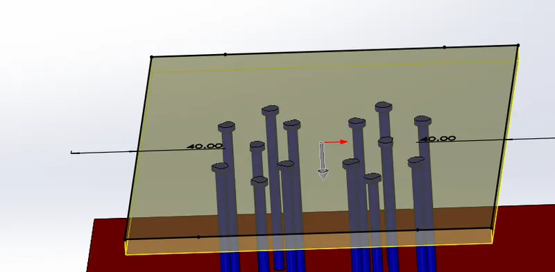
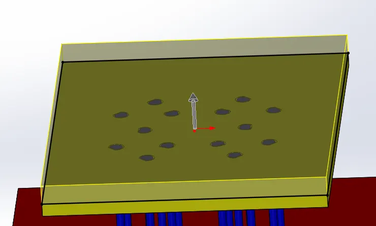
Now create a slot for the pin head in the rectangular plate.
Create another rectangular plate of same dimensions as pe the previous rectangle and extrude for 15mm verticallly upward direction.
Next we have to create a sprue and runner under the cavity block for the passage of molten plastic in the block at desired locations.
From the molding nozzle, the sprue leads into the runner, which then directs the melt into the mold cavity through the gate. At the end of the runner is the gate leading into the mold cavity. The gate leaves a surface blemish on the part. It is small and designed to freeze before the part, runner, or sprue freeze.
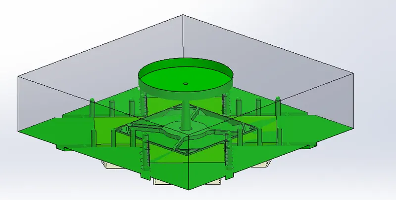
From the molding nozzle, the sprue leads into the runner, which then directs the melt into the mold cavity through the gate. At the end of the runner is the gate leading into the mold cavity. The gate leaves a surface blemish on the part. It is small and designed to freeze before the part, runner, or sprue freeze.
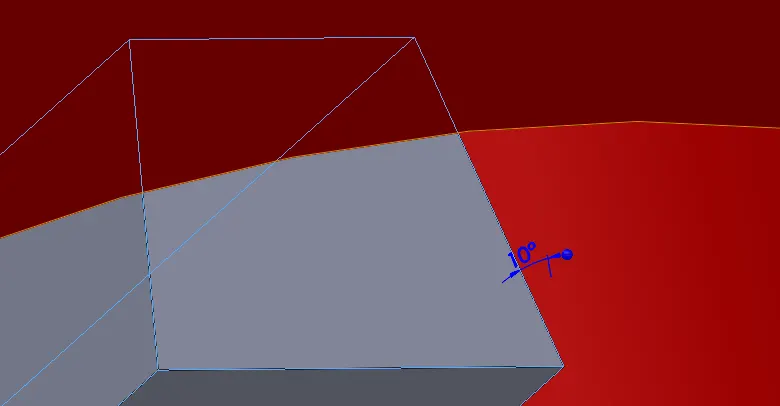
We create cooling channels by keeping in mind that we should provide uniform cooling throughout the mold so that defects such as warpage do not occur.
The diameter and lecght of the hole is described in below image,
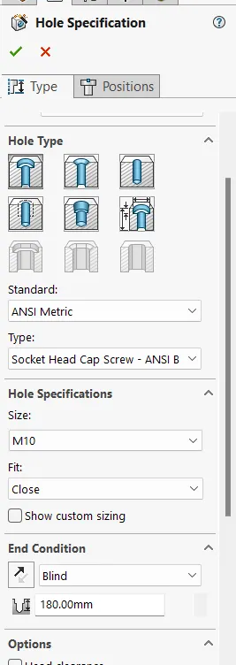
Apropriate colouring to the cooling channels are provided.
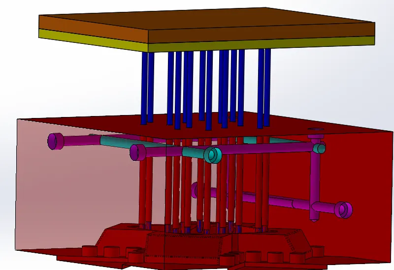
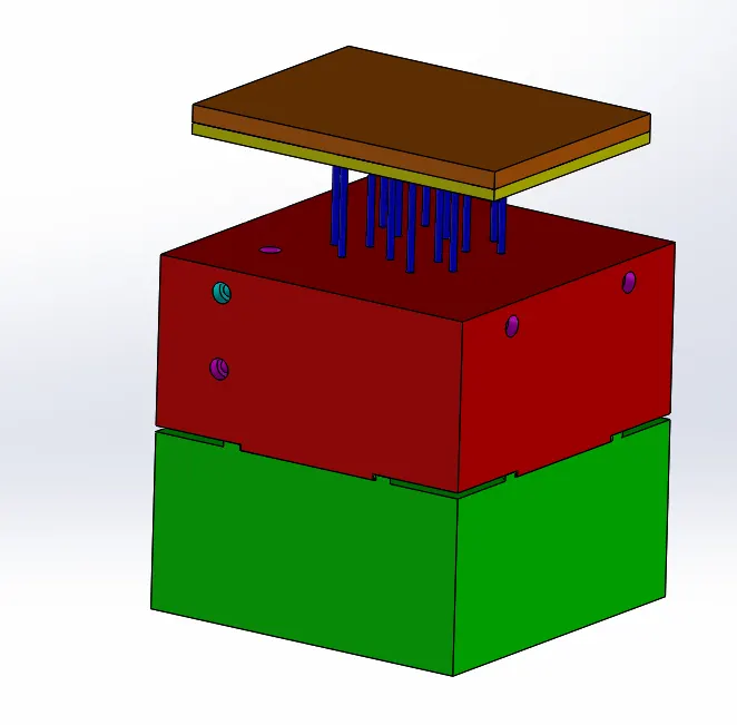
Complete assembly:
Conclusion:
Hence all the components such as mold blocks, inserts, sliders, ejector pins, plates, runner and gate system, bolts are create for the Plastic knob part component.