Project
AIM : To study, analyze and make a detail report on Baja All-Terrain vechile (ATV) model using
simulink and compare between its different modes.
OBJECTIVES: Prepare a technical report explaining the model properties & comments on the results
THEORY: ALL- TERRAIN VECHILE
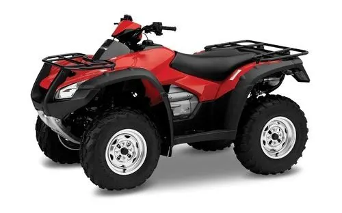
- The ATV is commonly called a four-wheeler in Australia, South Africa, parts of Canada, India and
the United States. They are used extensively in agriculture, because of their speed and light footprint.
- An all-terrain vehicle (ATV), also known as a light utility vehicle (LUV), a quad bike, or simply a quad,
as defined by the American National standards Institute(ANSI); is a vehicle that travels on low-pressure tires,
with a seat that is straddled by the operator, along with handlebars for steering control. As the name implies,
it is designed to handle a wider variety of terrain than most other vehicles. Although it is a Street-legal action
in some countries, it is not street-legal within most states, territories and provinces of Austrialia the United
States or Canada
- By the current ANSI definition, ATVs are intended for use by a single operator, although some companies have
developed ATVs intended for use by the operator and one passenger. These ATVs are referred to as tandem ATVs.
SIMULINK ATV MODEL :
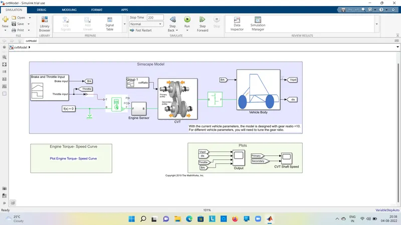
- BAJA ATV MODEL- CVT Model (Without dashboard).
- Following is the simulation model for the BAJA ATV Model without dashboard.
- In the above model simulation blocks are used and their purpose are as follows.
1. Signal builder : The signal builder block allows you to create interchangeable groups of
piecewise linear signal soures and use them in a model.
2. Goto:The Goto block passes its input to its corresponding From blocks. The input can be a real- or
complex-valued signal or vector of any data type. From and Goto blocks allow you to pass a
signal from one block to another without actually connecting them.
3. Simulink ps converter:The Simulink-PS Converter block converts the input Simulink
signal into a physical signal.
4. Generic Engine :Represents a system level model of spark-ignition and diesel engines suitable
for use at intial stages of modeling when only the basic parameeters are available .
5. Solver Configuration :The Solver Configuration block specifies the solver parameters
that your model needs before you can bigen simulation.
6. Mechanical Rotational Reference:The Mechanical Rotational Reference block represents a reference
point, or frame, for all mechanical rotational ports.
7. Engine Sensor :It's a subsytem of which following blocks are used as per correspondng.
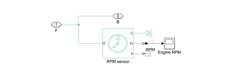
1.Ideal Rotational motion sensor:The Ideal Rotational Motion Sensor block represents an ideal mechanical
rotational motion sensor, that is, a device that converts an across variable measured between two mechanical
rotational nodes into a control signal proportional to angular velocity or angle.
2.Mechanical Rotational Reference:The Mechanical Rotational Reference block represents a reference
point, or frame, for all mechanical rotational ports.
3.PS-Simulink Converter:The PS-Simulink Converter block converts a physical signal into a Simulink
output signal.
4.Scope:The Scope block displays its input with respect to simulation time.
5.PS-Terminator: PS Terminator block to cap physical signal output ports that do not connect to other blocks.
8. CVT :It's a subsytem of which following blocks are used as per correspondng.
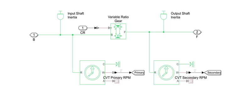
1.Inertial : The block represents an ideal mechanical rotational inertia.
2.Ideal Rotational motion sensor:The Ideal Rotational Motion Sensor block represents an ideal mechanical
rotational motion sensor, that is, a device that converts an across variable measured between two mechanical
rotational nodes into a control signal proportional to angular velocity or angle.
3.Mechanical Rotational Reference:The Mechanical Rotational Reference block represents a reference
point, or frame, for all mechanical rotational ports.
4.PS-Simulink Converter:The PS-Simulink Converter block converts a physical signal into a Simulink
output signal.
5.Goto:The Goto block passes its input to its corresponding From blocks. The input can be a real- or
complex-valued signal or vector of any data type. From and Goto blocks allow you to pass a
signal from one block to another without actually connecting them.
6.PS-Terminator: PS Terminator block to cap physical signal output ports that do not connect to other blocks.
7.Variable Ratio Transmission:Its represents a variable ratio gearbox such as implemented as by mechanical
belt cvt ,elecric transmission.
9. Simple Gear: Represents a fixed ratio of gear or gear box.
10. Vechile Body-CVT : It's a subsytem of which following blocks are used as per correspondng.
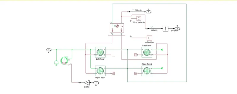
1.Inertial : The block represents an ideal mechanical rotational inertia.
2.Double Sheo Brake :he Double-Shoe Brake block represents a frictional brake with two pivoted
rigid shoes that press against a rotating drum to produce a braking action. The rigid shoes sit
inside or outside the rotating drum in a diametrically opposed configuration. A positive actuating
force causes the rigid shoes to press against the rotating drum.
3.Gain:The Gain block multiplies the input by a constant value (gain). The input and the gain can
each be a scalar, vector, or matrix.
4.Tyre:Represents the longitudinal behaviour of a highway tire characterised by the tire magic
formula.
5.PS-Terminator: PS Terminator block to cap physical signal output ports that do not connect to
other blocks.
6.Vechile Body:The Vehicle Body block represents a two-axle vehicle body in longitudinal motion.
The vehiclecan have the same or a different number of wheels on each axle. For example, two
wheels on the front axleand one wheel on the rear axle. The vehicle wheels are assumed identical
in size. The vehicle can also have a center of gravity (CG) that is at or below the plane of travel.
7.PS Constant:The PS Constant block generates a physical signal of a constant value.
8.PS-Simulink Converter:The PS-Simulink Converter block converts a physical signal into a Simulink
output signal.
9.Integrator:The Integrator block outputs the value of the integral of its input signal with respect
to time.
11.From:The From block accepts a signal from a corresponding Goto block, then passes it as output.
The data type of the output is the same as that of the input from the Goto block. From and Goto
blocks allow you to pass a signal from one block to another without actually connecting them.
12.Scope:The Scope block displays its input with respect to simulation time.
INPUT FOR THE MODEL:
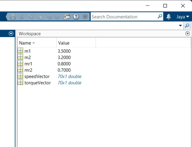
1.The variable m1,m2 stands for the mass input for the inertial at input shaft and output shaft at
CVT transmission system.
2.The variables speed vector and torque vector are the engine parameters for the generic engine
which provides relation between torque and rpm of the engine.
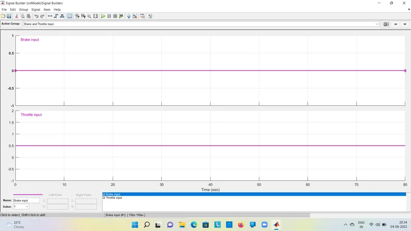
3.Using the signal builder to throttle and brake input while simulation is running .
PROCESS OF THE MODEL :
1.The initial condition engine block is set to the parameters ,throttle input to the engine
changes parameters of speed,torque and others.Egine parameters are provided by variables
speed vector and torque vector.
2.After throttl input ,it provides rpm,torque and various factors depending engine parameters.
3.If the generic engine to output, engine sensor block are recorded as the rpm, during the simulation,
and forward towards the transimission.
4.In the CVT block, two inputs one is signal builder and other one is engine , it provides cvt ratio.
5.In cvt block, two ideal rotational sensor blocks and two inertia blocks each for input and output
shafts respectively,there be variable ratio gear changes its gear ratio during simulation to cvt ratio.
6.After singnal from cvt passes through simple gear block it acts as differential gearbox before passing
vehicle body.
7.In the vehicle body block,two inputs one from the engine ,which get from simpler gear block other from
brake input.
8. We also get the velocity of the vehicle as in output from the vehicle body block.
RESULT :200 SEC SIMULTION
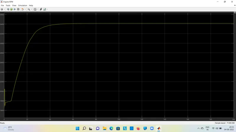
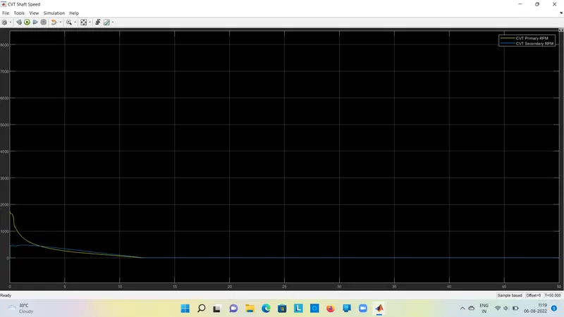
1.As the primary shaft is connected to the engine it looks similar to the rpm but due to the inertia and other factors
the primary shafft rpm will not be the same as the engine.
2.Hence primary shaft will not be the same as the engine but will have similar rpm with considering some loses.
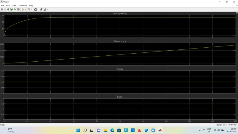
1. We can verify that the throttle value and brake value are constant during simulation.
2.Initially, the velocity of the vehicle is increased rapidly and then after a certain point when
reaches its constant rpm, the velocity of hte vehicle becomes a constant.
3.As we know integration of hte velocity gives us the distance travel by vehicle.
SIMULINK MODEL FOR BAJA ATV WITH CVT USING DASHBOARD :
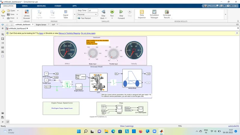
In this model we have a dashboard which contains knob to control the inputs.
In this case, the inputs 'Throttle' and 'Brake' are not provide using signal builder.
A knob is provided to control both the parameters in real-time for the users.
OUTPUT FOR ABOVE MODEL :
VEHICLE SPEED :
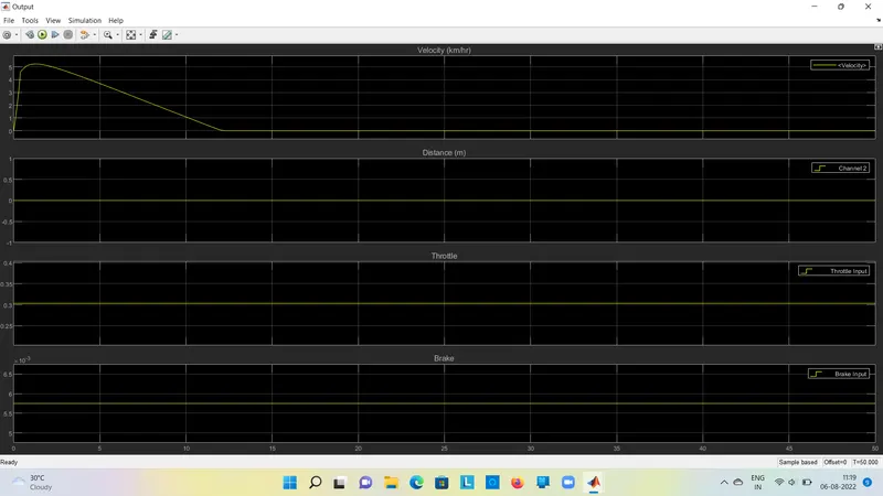
It can be observed from the graph that velocity of the vehicle increases from 0 and 50kmph when
Throttle value is 0.3 and brake input 0.once brake values is increases ,then the velocity will be rapidly
decreases. This explains the direct relation of vehicle velocity with respect to throttle and brake inputs.
CVT SHAFT RPM :
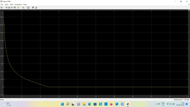
ENGINE RPM :