Project 1- Traffic Jam Assistant Feature
Traffic Jam Assistant Feature
# Model Is developed
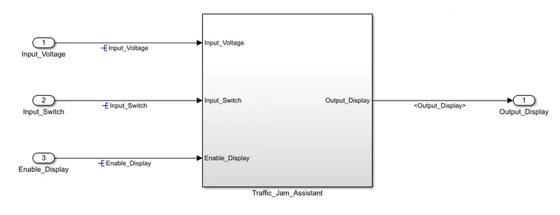
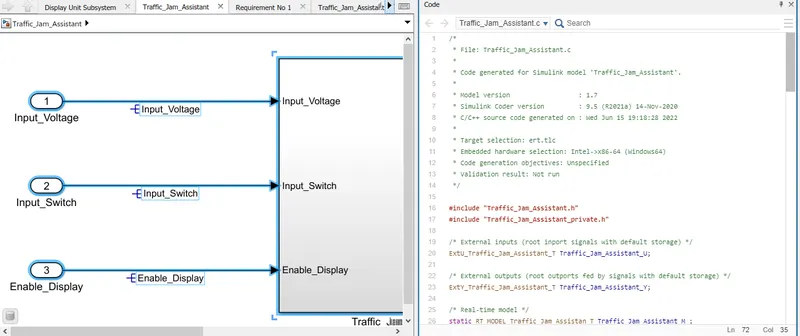
- In the main subsystem at the input side, 3 Input are created as given in the above model.
- A signal output signal is connected to the output side.
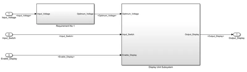
- Inside the main subsystem 2 other subsystems are crested according to the 2 requiremnts given.
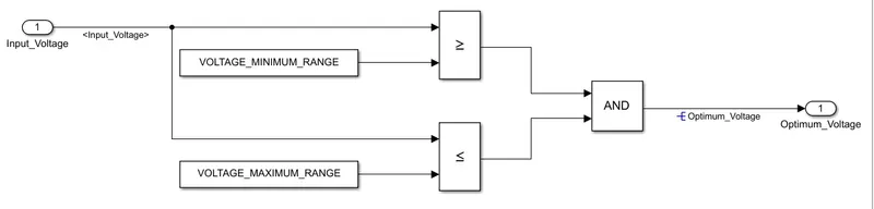
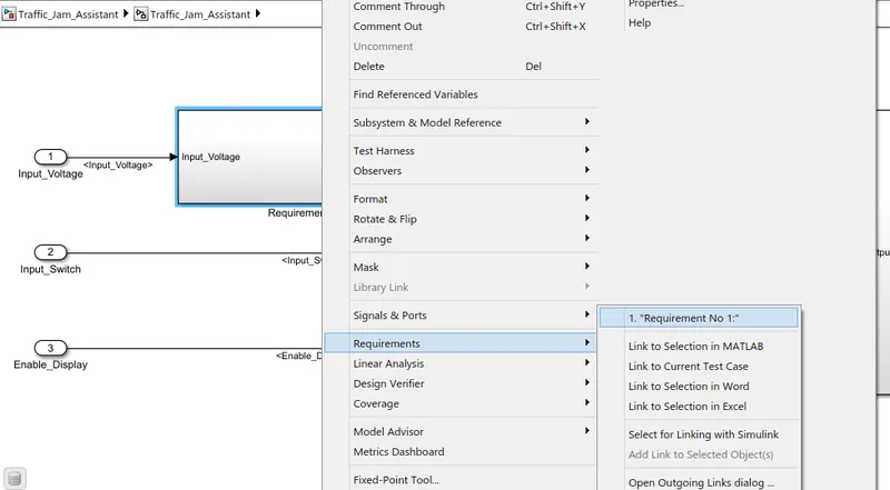
- As per Requirement 1
Input Signal “Input_Voltage” is compared against voltage values “VOLTAGE_MINIMUM_RANGE” & “VOLTAGE_MAXIMUM_RANGE”.
Incoming input signal “Input_Voltage” must be greater than – equal to “VOLTAGE_MINIMUM_RANGE” and less than – equal to “VOLTAGE_MAXIMUM_RANGE”.
Output signal from here is “Optimum_Voltage” which will be one of the inputs to the subsystem “DisplayUnit”.
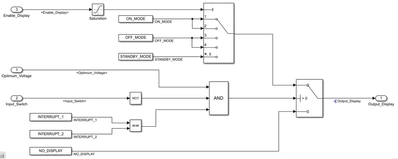
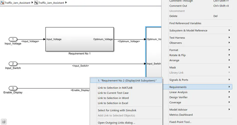
- Requirement No 2 (DisplayUnit Subsystem):
Input Signals are “Optimum_Voltage”, “Input_Switch”,“Enable_Display”. Signal “Enable_Display” must be saturated between the range 0 – 7. Output signal from the subsystem is “Output_Display”.
Input Signal “Enable_Display” is compared against pre – defined set of values in a multiport switch. Total data ports in the multiport switch is 5.
Multiport switch inputs 1 & 2 is connected to calibration signal “ON_MODE”, Multiport switch inputs 3 & 4 is connected to calibration signal “OFF_MODE” while Multiport switch input 5 is connected to calibration signal “STANDBY_MODE”.
The output from Multiport switch is connected to the first input port of the Switch block. The third input port of the Switch block is connected to the calibration signal “NO_DISPLAY”.
Meanwhile NOT value of input signal “Input_Switch” is compared in an AND gate against input signal “Optimum_Voltage” and the output from comparing if calibration signals “INTERRUPT_1” & “INTERRUPT_2” are equal. The output of the AND gate is the second input of the switch block.
The output from the switch block is “Output_Display”.
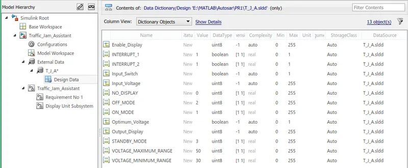
# SLDD Creation
# Requiremnt Tagging
# MAB Guidelines
# Code Genartion Using Embedded Coder
- For the code generation the solver setting is set as Fixed Step
- The Target File is set to 'ert.tlc'
- Generate Code option is selected from Apps -> Embedded Coder, the AutoCode Generation begins
/*
 * File: Traffic_Jam_Assistant.c
 *
 * Code generated for Simulink model 'Traffic_Jam_Assistant'.
 *
 * Model version                  : 1.7
 * Simulink Coder version         : 9.5 (R2021a) 14-Nov-2020
 * C/C++ source code generated on : Wed Jun 15 19:18:28 2022
 *
 * Target selection: ert.tlc
 * Embedded hardware selection: Intel->x86-64 (Windows64)
 * Code generation objectives: Unspecified
 * Validation result: Not run
 */

#include "Traffic_Jam_Assistant.h"
#include "Traffic_Jam_Assistant_private.h"

/* External inputs (root inport signals with default storage) */
ExtU_Traffic_Jam_Assistant_T Traffic_Jam_Assistant_U;

/* External outputs (root outports fed by signals with default storage) */
ExtY_Traffic_Jam_Assistant_T Traffic_Jam_Assistant_Y;

/* Real-time model */
static RT_MODEL_Traffic_Jam_Assistan_T Traffic_Jam_Assistant_M_;
RT_MODEL_Traffic_Jam_Assistan_T *const Traffic_Jam_Assistant_M =
  &Traffic_Jam_Assistant_M_;

/* Model step function */
void Traffic_Jam_Assistant_step(void)
{
  uint8_T tmp;

  /* Switch: '<S2>/Switch' incorporates:
   *  Constant: '<S3>/Constant'
   *  Constant: '<S3>/Constant1'
   *  Inport: '<Root>/Input_Switch'
   *  Inport: '<Root>/Input_Voltage'
   *  Logic: '<S2>/AND'
   *  Logic: '<S2>/NOT'
   *  Logic: '<S3>/AND'
   *  RelationalOperator: '<S3>/Relational Operator'
   *  RelationalOperator: '<S3>/Relational Operator1'
   */
  if ((Traffic_Jam_Assistant_U.Input_Voltage >= 30) &&
      (Traffic_Jam_Assistant_U.Input_Voltage <= 50) &&
      (!Traffic_Jam_Assistant_U.Input_Switch) &&
      Traffic_Jam_Assistant_ConstB.RelationalOperator) {
    /* Saturate: '<S2>/Saturation' incorporates:
     *  Inport: '<Root>/Enable_Display'
     */
    if (Traffic_Jam_Assistant_U.Enable_Display < 7) {
      tmp = Traffic_Jam_Assistant_U.Enable_Display;
    } else {
      tmp = 7U;
    }

    /* End of Saturate: '<S2>/Saturation' */

    /* MultiPortSwitch: '<S2>/Multiport Switch' */
    switch (tmp) {
     case 1:
      /* Outport: '<Root>/Output_Display' incorporates:
       *  Constant: '<S2>/Constant3'
       */
      Traffic_Jam_Assistant_Y.Output_Display = 1U;
      break;

     case 2:
      /* Outport: '<Root>/Output_Display' incorporates:
       *  Constant: '<S2>/Constant3'
       */
      Traffic_Jam_Assistant_Y.Output_Display = 1U;
      break;

     case 3:
      /* Outport: '<Root>/Output_Display' incorporates:
       *  Constant: '<S2>/Constant1'
       */
      Traffic_Jam_Assistant_Y.Output_Display = 2U;
      break;

     case 4:
      /* Outport: '<Root>/Output_Display' incorporates:
       *  Constant: '<S2>/Constant1'
       */
      Traffic_Jam_Assistant_Y.Output_Display = 2U;
      break;

     default:
      /* Outport: '<Root>/Output_Display' incorporates:
       *  Constant: '<S2>/Constant2'
       */
      Traffic_Jam_Assistant_Y.Output_Display = 3U;
      break;
    }

    /* End of MultiPortSwitch: '<S2>/Multiport Switch' */
  } else {
    /* Outport: '<Root>/Output_Display' incorporates:
     *  Constant: '<S2>/Constant5'
     */
    Traffic_Jam_Assistant_Y.Output_Display = 0U;
  }

  /* End of Switch: '<S2>/Switch' */
}

/* Model initialize function */
void Traffic_Jam_Assistant_initialize(void)
{
  /* (no initialization code required) */
}

/* Model terminate function */
void Traffic_Jam_Assistant_terminate(void)
{
  /* (no terminate code required) */
}

/*
 * File trailer for generated code.
 *
 * [EOF]
 */
# CONCLUSION
The model for Traffic Jam Assistant is developed using MATLAB Simulink as per MBD guidelines.
Simulink Data Dictionary is created for the model and is linked to the model.
Requirement document is tagged with each subsystem.
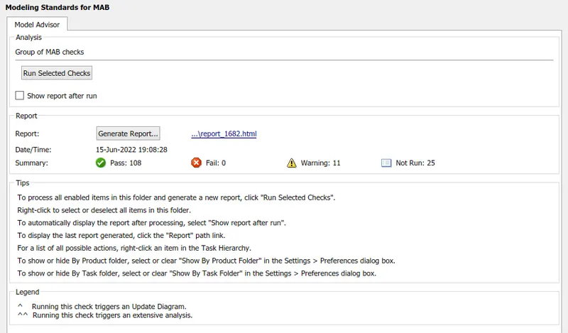
Model Advisor Report is performed, and the the Report is Generated
Code generation is executed using Embedded Code.