Project-1: Powertrain for aircraft in runways
Solution:
Part A:
1. Total weight of various types of aircrafts:
Weight and balance is a key factor in not only design but in the performance and stability of an aircraft under various operating conditions. Aircraft balance about their Center of Gravity (C.G.), whose location determines aircraft characteristics. The position of the center of gravity is affected by the total and the distribution of weight throughout the aircraft. Weight parameters ensure the wings and overall structure can support the aircraft throughout all flight envelopes. Before every flight, pilots must determine the weight and balance to ensure the aircraft operates within manufacturer specifications.
- Standard Empty Weight: This weight consists of the airframe, engines, and all items of operating equipment that have fixed, permanently installed locations in the airplane, including fixed ballast, hydraulic fluid, unusable fuel, and full engine oil
- Basic Empty Weight: The basic empty weight (BEW) of standard airplane, optional equipment, unusable fuel (fuel that cannot be drained), and full operating fluids, including full engine oil
- Licensed Empty Weight: Like BEW, but does not count full engine oil, only undrainable oil
- Gross Landing Weight: Takeoff weight minus the fuel burned en-route
- Ramp Weight: Airplane loaded for flight before engine start
- Zero Fuel Weight: Weight of the aircraft before the addition of fuel
- Gross Takeoff Weight: Weight of the airplane just before brake release to begin the takeoff roll
- Useful Load: Weight of crew and usable fuel
- Maximum Ramp Weight: Maximum weight for ground operations
- Maximum Takeoff Weight: Maximum weight for takeoff
- Maximum Landing Weight: Maximum weight for landing based on the stress of impact on gear
- Payload: The weight of only the passengers, baggage, and cargo
An aircraft’s empty weight, fuel, passengers & cargo must not weigh more than the aircraft’s Maximum Gross Takeoff Weight.
| Aircraft | Empty Weight | Max Fuel Weight | Max Cargo Weight | Max Gross Takeoff Weight |
| Antanov AN-225 | 285,000 kg | 300,000 kg | 190,000 kg | 640,000 kg |
| Airbus A380-800 | 277,000 kg | 254,000 kg | 84,000 kg | 575,000 kg |
| Boeing 747-800 | 220,100 kg | 194,000 kg | 134,000 kg | 447,700 kg |
| Airbus A340-500 | 168,000 kg | 175,000 kg | 54,000 kg | 372,000 kg |
| Boeing 777-300ER | 168,000 kg | 145,500 kg | 67,100 kg | 352,000 kg |
| Boeing 787-10 | 135,500 kg | 101,500 kg | 57,300 kg | 254,000 kg |
| Boeing 737-900 | 44,700 kg | 24,000 kg | 20,200 kg | 85,000 kg |
| Airbus A320-100 | 42,600 kg | 22,100 kg | 20,000 kg | 68,000 kg |
| Embraer 190 | 28,800 kg | 13,000 kg | 13,100 kg | 48,000 kg |
| Gulfstream G650 | 24,500 kg | 21,900 kg | 3,000 kg | 45,200 kg |
| Bombardier CRJ900 | 21,850 kg | 8,900 kg | 2,760 kg | 36,500 kg |
| Bombardier Q400 | 17,800 kg | 5,300 kg | 8,500 kg | 28,000 kg |
| Learjet 75 | 6,300 kg | 2,750 kg | 1,300 kg | 9,700 kg |
| Cessna Citation CJ4 | 4,700 kg | 2,650 kg | 1,000 kg | 7,800 kg |
| Beechcraft King Air B100 | 3,200 kg | 1,450 kg | 1,900 kg | 5,400 kg |
| Diamond DA50 RG | 1,450 kg | 155 lbs | 560 kg | 2,000 kg |
| Beechcraft Bonanza G36 | 1,150 kg | 200 kg | 385 kg | 1,660 kg |
| Cessna 206H | 990 kg | 235 kg | 520 kg | 1,630 kg |
| Sirrus SR22 | 1,000 kg | 220 kg | 430 kg | 1,630 kg |
| Cessna 172R | 770 kg | 170 kg | 255 kg | 1,100 kg |
2. Difference between Ground Speed and Air Speed:
The difference between Ground speed and Air speed is given below:
Ground Speed:
- It is the airplane’s speed relative to the surface of the Earth and is the vector sum of aircrafts true airspeed and wind speed and the direction.
- If the aircraft is flying in the same direction as the wind is blowing, the aircraft experiences tailwind, and its ground speed is higher than its airspeed. On the other hand, if the wind is blowing against the direction the aircraft is traveling in, the aircraft experiences headwind, and its ground speed is lower than its airspeed.
- A headwind subtracts from the ground speed, while a tailwind adds to it. Winds at other angles to the heading will have components of either headwind or tailwind as well as a crosswind component.
- An aircraft heading vertically would have a ground speed of zero.
- It is vital for accurate navigation that the pilot has an estimate of the ground speed that will be achieved during each leg of a flight.
- It is measured using GPS, and indicated airspeed is measured using sensors on the plane called pitot tubes.
Air Speed:
- It is the speed at which an aircraft is moving relative to the air it is flying in.
- Pilots commonly use three different types of airspeed: indicated airspeed, calibrated airspeed, and true airspeed.
- Indicated airspeed is an airspeed that is calculated directly off an aircraft’s pitot-static system. It’s the calculated off the aircraft’s dynamic pressure – the difference between its total pressure and static pressure.
- The dynamic pressure depends not only on the aircraft’s speed, but also on the density of the air it is flying in. As such, the higher the aircraft flies – and the lower the air density as a result – the bigger the difference between indicated and true airspeed is.
- Calibrated airspeed is indicated airspeed adjusted for a variety of errors. Just as an example, one of the things it’s adjusted for is the flap position. The reason for that is that at different flap positions, air flows differently around the pitot-static system and affects the indicated airspeed readings.
- True airspeed is, the actual speed at which an aircraft is moving relative to the air it is traveling in. It’s calibrated airspeed adjusted for the the exact conditions (altitude, air temperature, etc.) that the aircraft is flying in.
3. It is not recommended to use aircraft engine power to move it on the ground at Airport because of the following reasons:
- Generally most of the airplane can move itself in reverse manner by making use of reverse thrust technology.But in most of the practical it is not possible because when airplanes start using reverse thrust it will consume lot of fuels as well as causes lot of noise and also hazardous for the people working near by.
- The thrust produced resulting jet blast might cause damage to the terminal building or equipment. Engines close to the ground may also blow sand and debris forward and then suck them into the engine, causing damage to the engine.
- Effectively a loss of control can happen, especially during high power engine running. Damage can occur to the aircraft itself, other aircraft nearby or to air side structures.
- There is a risk of injury to ground support personnel who may be in relatively close proximity to the aircraft.
- To solve this kind of issue we use a towing vehicle which helps to tow the vehicle in reverse dierection and it eill be tugged until it reaches a safe place and from there onwards airplane will move by itself for further take off.
- It is easier for truck driver to see the surroundings better than the pilot sitting in the cockpit with limited window. The pushback driver knows the airport better than the pilot.
- It also saves fuel virgin Atlantic hadproposed a new system in which pushback truck will move the aircraft all the way to runway to save fuel and reduce impact of environment.
4.How an aircraft is pushed to runway when its ready to take off?
The aircraft is pushed onto a runway with the help of a towing vehicle also known as tow tractor when it is ready for take-off. Taxi-Ing the aircraft involves moving it along the ground from where it has been parked, up to the start of the runway. During taxi-Ing, there are other checks which need to be done, mainly to ensure that the steering on the ground works as it should do.
Pushback is an airport procedure during which an aircraft is pushed backwards away from an airport gate by external power. Pushbacks are carried out by special, low-profile vehicles called pushback tractor or tugs.
Although many aircraft are capable of moving themselves backwards on the ground using reverse thrust, the resulting that might cause damage to the terminal building or equipment. Engines close to the ground may also blow sand and debris forward and then suck them into the engine, causing damage to the engine. A pushback is therefore the preferred method to move the aircraft away from the gate.
5. Learn about take off power, tyre design, rolling resistance, tyre pressure, brake forces when landing.
- Take Off Power:
Take off is the phase of the flight in which an aeroplane leaves ground and becomes airbone.For lighter aircraft full power is given during take off where as on the other hand large cargo carriers aircraft make use of less power during take off inorder to inrease the life span of engine,reduce maintenance cost ,reduce engine heat and also for a smooth take off flight.
The Take-off Power is the amount of power that an engine is allowed to produced for a limited period of time for take-OFF. The normal take-off is one in which the airplane is headed into the wind, or the wind is very light. Also, the takeoff surface is firm and of sufficient length to permit the airplane to gradually accelerate to normal lift-off and climb-out speed, and there are no obstructions along the takeoff path.
The airplane should be carefully aligned with the intended takeoff direction, and the nose wheel positioned straight, or centered. After releasing the brakes, the throttle should be advanced smoothly and continuously to takeoff power. An abrupt application of power may cause the airplane to yaw sharply to the left because of the torque effects of the engine and propeller.
There are two reasons for making a takeoff as nearly into the wind as possible:
- Aircraft speed will be less, therefore reducing wear and stress on landing gear
- Shorter ground roll and therefore much less runway length
The total energy of an aircraft flying in the atmosphere can be calculated using equation,
E = ½ m v2+ mgh
However, the engines mounted onto the wings of the plane are required to provide additional energy per time, power, in order to keep the aircraft flying at a constant altitude and speed. This extra power needed to overcome the drag acting on the airplane and is calculated using
P = (dh/dt) m g
where (dh/dt) is the decent speed required to keep the plane's speed constant if the engines fail.
- Tyre Design:
An aircraft tyre are deisgned to withstand extreme heavy loads by absording shocks during and there by providing cushioning effect. The number of tires required for an aircraft depends on the total weight of aircraft as the weight needs to be distributed evenly. Aircraft tyre are designed to facillitate stability in high crosswind condition,to chanalize the water away for preventing skidding and helps to give a good braking effect.Aircraft tires are usually inflated by nitrogen air inorder to reduce expansion and contraction from extrerme changes in ambient pressure and tempurature.This type of inert gases will eliminate the possibilty of tire explosion. Aircraft tire design are set into an aircraft based on its application and also suffeicient clearance with the ground for allowing tyre growth which happens when centrifugal force is at high speed.
Carcass plies are used to form the tyre. They are sometimes called casing plies. An aircraft tyre is constructed for the purpose it serves.
- They support the weight of an aircraft while it is on the ground.
- It also provides the necessary traction for braking and stopping of an aeroplane.
- Tyre also helps to absorb the shock of landing and provide cushioning the roughness of takeoff, roll-out, and taxi operations.
Unlike an automobile or truck tyre, it does not have to carry a load for a long period of continuous operation. However, an aircraft tyre absorbs the high impact loads of landing, and also it’s operating at high speeds for a short time when required. Two types of tires are used in an aircraft application: bias-ply tires and radial tires. The basic difference between a radial tyre and bias (cross-ply) tyre is the lay of the plies within the tyre carcass. The remainder of the tyre is very similar in construction in both.
- Rolling Resistance:
Rolling resistance or the rolling friction is the force that resists the motion of a body rolling on a surface. The rolling resistance can be expressed as, Fr = c W /r
W = m * ag
where Fr - rolling resistance or rolling friction (N)
c - rolling resistance coefficient
m - mass of body (kg, lb)
ag - acceleration of gravity (9.81 m/s2)
r - radius of wheel (mm, in)
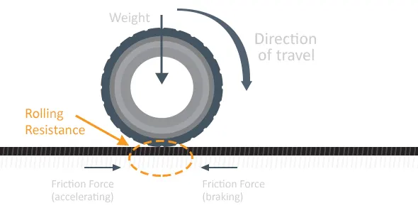
Rolling resistance, sometimes called rolling friction or rolling drag, is the force resisting the motion when a body (such as a ball, tire, or wheel) rolls on a surface. It can be seen in the aircraft takes off from the runway and while landing at the runway with the help of other wheels. The friction between aircraft and runway will be proportional to the normal force exerted by the aircraft on the runway.
F=µ(W-L)
The normal force will be the difference between Weight(W) of aircraft and lift (L), the friction coefficient (µ) will be typically of a magnitude of 0.02 for a standard tarmac runway.
It is the force resisting the motion when a body rolls on the surface. It can be observed in the aircraft when its take-off from the runway and while landing at the runway with their wheels.
- Tyre Pressure:
Aircraft tyres are designed to withstand heavy loads and shocks during landing and take off and also needs to distribute weight evenly. As per research and testing it is found that aircraft tyres are able to sustain pressure upto 800 psi.Generally to note the tyre pressure of an aircraft a special type of sensors are used,its daigram is given below:
There are 2 primary parameters which is hazardous to the aircraft tires:
- Deflation: Here the tire deflates in a controlled ma-nner with minimum dierect consequence to other system.
- Explosive breakup: In this case the tire deflates or bursts in an uncontrolled manner with a probablity of causing damage to other secondary system,which further can cause a major crash landing incidents.
The three major factors that affect tyre performance are,
- Centrifugal force.
- Heat generation.
- Tensile, Compression and Shear Forces.
- Brake Forces when Landing:
Braking an aircraft is a challenging job for most of the pilots especially during landing in a rainy and cross wind environment.-Inorder to encounter this kinds of problem pilots usually make use of spoilers and reverse thust method inorder to have a safe landing so that the energy required to apply brakes on tires can be reduced and henceforth they do not skid.
The Figure shows the forces acting on the aircraft and the wheels during braking time and its electrical equivalent.
where,
The normal force on the aircraft depends on its weight and lift acting on the braking moment. The normal force corresponding to each wheel, considering that each wheel receives one third of the resulting force is described as follows:
N=(W-L)/3
where,
Tr is the counter torque generated by the brake actuator and FMotor is the motor traction. The wheel and aircraftequations are related by the wheel slip. The slips relates the aircraft speed and the wheel speed, as described by the following equation
S=1-(Wr/Wt)
where,
Part B:
6. A. With necessary assumptions, calculate the force and power required to push / pull an aircraft by a towing vehicle.
- Rolling Resistance Force (Frr) = Crr⋅m⋅g
Where, Frr= Rolling Resistsnce Force in N
Crr= Coefficient of Rolling resistsnce
g = Gravity 9.81
- Aerodynamic Force (Fad)=0.5⋅Cd⋅ρ⋅A⋅V2
Where, Fad= Aerodynamic Force in N
Cd = Drag Coefficient
ρ = Air Density in Kg/m^3
A = Frontal Area in m^2
V= Velocity of Vehicle in m/s
- Total Force (Ft) = Frr+Fad
Where, Frr= Rolling Resistance in N
Fad= Aerodynamic Fornce in N
- Power Required (Pr) = Ft⋅V
Where, Ft= Total Force in N
V= Velocity of Vehiclein m/s
Assuming the values for Boeing 777 Airplane,
6.B. Develop the model for the calculated force and power using Simulink.
Blocks Used:
- Constant
- Add
- Product
- Square
- Display
Logic: Rolling Resistance Calculation is achieved by Constant, Add and Product blocks as per above equation. Air Drag Calculation is done by Constant,Add, Product, Square Blocks as per above equation. Both these values are fed as input to Add block to get Total Force. Then this is fed to Product block with Speed block to get the Power. Outputs are shown via Display Block.
Simulink Model:
7. A. Design an electric powertrain with type of motor, it’s power rating, and energy requirement to fulfill aircraft towing application in Simulink. Estimate the duty cycle range to control the aircraft speed from zero to highest. Make all required assumptions. Prepare a table of assumed parameters. Draw a block diagram of powertrain.
Considering the values from above question,
Rolling Resistance force for Aircraf(Frr)=29510.05 N (29.510KN)
Power Required Force Aircraft(Pr)=137.375Kw
Radius of Tyre (r) = 0.813m
Gear Ratio (G)=10
Motor Efficiency (ηm)=95% = 0.95
Transmission efficiency (ηt)=85% = 0.85
Required Torque for the vehicle wheel, Tw=Frr⋅r
Tw=29.510*0.813= 23.99KNm
Motor Torque, Tm=Tw/G⋅ηt
Tm= 23.99/10*0.85= 2.823KNm
Required Motor Torque, Tmr=Tm/ηm
Tmr= 2.823/0.95 = 2.97KNm
Total power Required for Motor Considering all Efficiency, Pt=Pr/ηm*ηt
Pt= 137.375/0.95*0.85 = 170.124kW
If we consider, The towing Vehicle operation was completed in 15 min i.e., 0.25 hours
Total Energy Consumed, Et=Pt⋅t
Et= 170.124*0.25 = 42.53KWh
If we consider the battery capacity=220 kw is used by the towing vehicle then. The duty cycle range to control the speed from O to max speed (3m/s) is given as
Dc=Pt/Pr
Dc=170.124/220=0.7733=77.33%
Therefore the controller will be able to provide a duty cycle ranging from 0 to 77.33% in order to control the towing speed.
7.B. Design the parameters in excel sheet.