Project - Position control of mass spring damper system
Solution:
Blocks used:
Clock - Provides current simulation time
Display - displays data
pulse generator - used to generate a refence signal
Sum - used too add/subtract 2 signals
Gain - multiplies the inputt signal by the gain value specified
Integrator - used to integrate the signal
Derivative - provides the derivative of the signal with respect to time
Scope - displays the output waveform
Transfer function - is used to insert transfer function in the model
Logic:
- The transfer function for the spring mass damper system is obtained
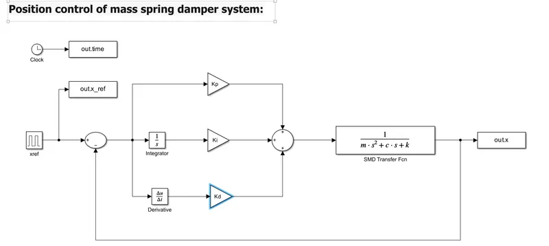
- The simulation model for the system is built in the simulink
- PID controller is added to the model to adjust the force on mass so that it follows the reference signal
- The output position is subtracted from the reference signal to obtain the error signal
- The error signal is passed through proportinal gain block, integrator gain block through a integrator and the derivative gain block through a derivative block. All these signals are added in the sum block and passed into the transfer function block to obtain the position
- The tranfer function block is updated with the transfer function obtained for sring mass damper system
- The design parameters (Kp and Kd) and the poles are found using the matlab code
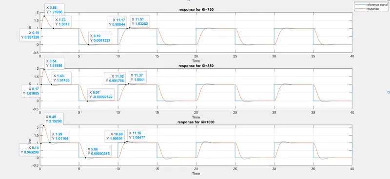
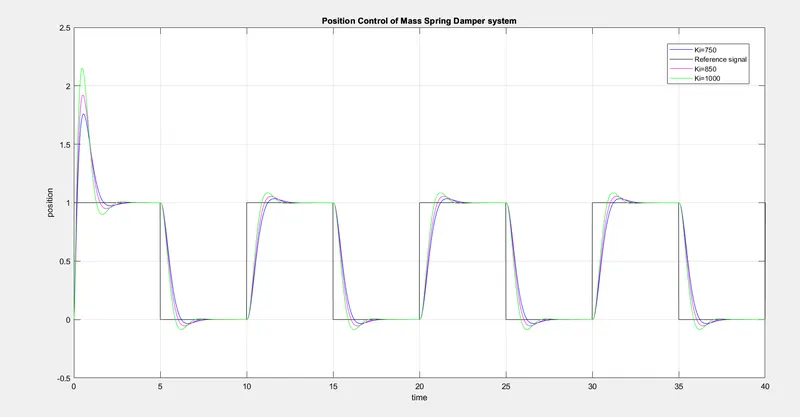
- The graph of time v/s postion is plotted for different values of Ki such that the output follows the reference signal with minimum deviation
Matlab Code:
clear all;
clc;
%Initialising the values
m=3.6;
k=400;
c=100;
wn=sqrt(k/m); %finding the value of wn
fn=wn/(2*pi);
zeta=c/(2*wn*m); %finding the value of zeta
A=[0 1; -k/m -c/m]; %initialsing matrix A
B=[0; 1/m]; %initialising matrix B
%finding poles
p1=-zeta*wn+wn*sqrt(zeta^2-1);
p2=-zeta*wn-wn*sqrt(zeta^2-1);
P=[p1; p2];
%Finding the gains,Kp and Kd
K=place(A,B,P);
Kp=K(1);
Kd=K(2);
Ki=1000;
Simulink screenshot:
Simulink Plots screenshot: