Powertrain system for an Aircraft and basics theory
Project 1: Powertrain for Aircraft in runways
SOLUTIONS:
(1) Search and list out the total weight of various types of aircraft.
Answer:-
The total weight of the aircraft is subdivided into two categories, viz, Design weight limit and Authorized weight limit.
Design Weight limit:
- An aircraft's gross weight is limited by several weight restrictions in order to avoid overloading its structure or to avoid unacceptable performance or handling qualities while in operation.
- Aircraft gross weight limits are established during an aircraft's design and certification period and are laid down in the aircraft's type certificate and manufacturer specification documents.
- The absolute maximum weight capabilities of a given aircraft are referred to as the structural weight limits. The structural weight limits are based on aircraft maximum structural capability and define the envelope for the CG charts (both maximum weight and CG limits).
- An aircraft's structural weight capability is typically a function of when the aircraft was manufactured, and in some cases, old aircraft can have their structural weight capability increased by structural modifications.
Authorized Weight limit:
- Aircraft authorised gross weight limits (also referred to as certified weight limits) are laid down in the aircraft flight manuals (AFM) and/or associated certificate of airworthiness (C of A). The authorised or permitted limits may be equal to or lower than the structural design weight limits.
- The authorised weight limits that can legally be used by an operator or airline are those listed in the AFM and the weight and balance manual.
- The authorised (or certified) weight limits are chosen by the customer/airline and they are referred to as the "purchased weights". An operator may purchase a certified weight below the maximum design weights because many of the airport operating fees are based on the aircraft AFM maximum allowable weight values. An aircraft purchase price is, typically, a function of the certified weight purchased.
- Maximum weights established, for each aircraft, by design and certification must not be exceeded during aircraft operation (ramp or taxying, takeoff, en-route flight, approach, and landing) and during aircraft loading (zero fuel conditions, centre of gravity position, and weight distribution).
- Weights could be restricted on some type of aircraft depending on the aircraft handling requirements; for example aerobatic aircraft, where certain aerobatic manoeuvres can only be executed with a limited gross weight.
- In addition, the authorised maximum weight limits may be less as limited by centre of gravity, fuel density, and fuel loading limits.
The types of weights are defined as follows:-
(i) Manufacture's Empty weight (MEW):- It is the weight of the aircraft as-built and includes the weight of the structure, power plant, furnishings, installations, systems and other equipment that are considered an integral part of an aircraft. This excludes any baggage, passengers, or usable fuel. It is also called as Manufacturer's Weight Empty (MWE) or Licensed Empty Weight.
(ii) Zero-fuel weight:- This is the total weight of the aeroplane and all its contents (including unusable fuel), but excluding the total weight of the usable fuel on board. As a flight progresses and fuel is consumed, the total weight of the aeroplane reduces, but the ZFW remains constant.
(iii)Maximum zero fuel weight (MZFW):- This is the maximum weight allowed before usable fuel and other specified usable agents (engine injection fluid, and other consumable propulsion agents) are loaded.
(iv) Operating empty weight:- It is the basic weight of an aircraft including the crew, all fluids necessary for operation such as engine oil, engine coolant, water, unusable fuel and all operator items and equipment required for flight but excluding usable fuel and the payload.
(v) Payload:- It is the carrying capacity of an aircraft. It includes cargo, people, extra fuel. In the case of a commercial airliner, it may refer only to revenue-generating cargo or paying passengers.
(vi) Maximum takeoff weight (MTOW):- This is the maximum weight at which the pilot of the aircraft is allowed to attempt to take off
(vii) Regulated takeoff weight (RTOW):- Depending on different factors (e.g. flap setting, altitude, air temperature, length of the runway), RTOW or maximum permissible takeoff weight varies for each takeoff. It can never be higher than MTOW.
(viii) Maximum landing weight (MLW):- This maximum weight at which an aircraft is permitted to land.
The following image depicts takeoff weight components.
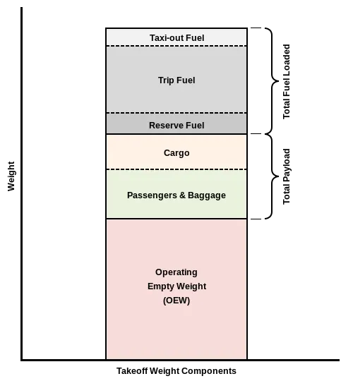
fig(i) The bar diagram representing the takeoff weight components
(ix) Maximum ramp weight (MRW):- It is the maximum weight authorized for manoeuvring (taxiing or towing) an aircraft on the ground. It is also called the maximum taxi weight (MTW).
(x) Aircraft gross weight:- It is the total aircraft weight at any moment during the flight or ground operation. This decreases during the flight due to fuel and oil consumption.
There is major commercial aircraft's weight shown in the below image:
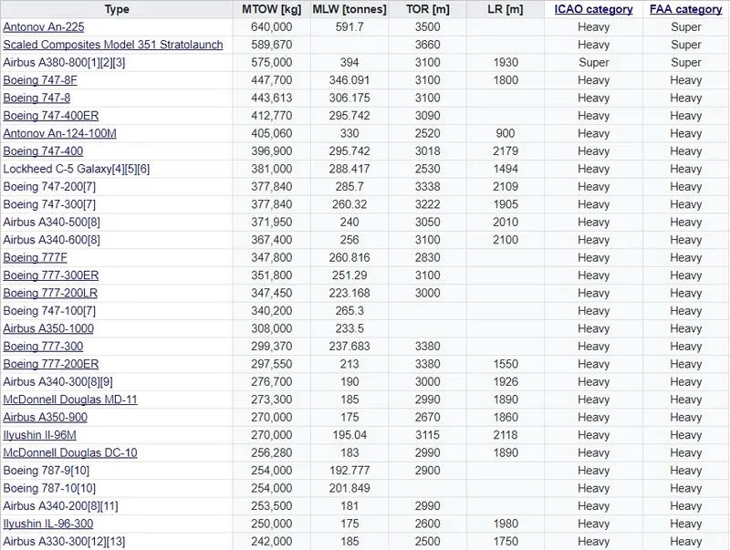
fig(ii) Commerical aircraft weights in tonnes
---------------------------------------------------------------------------------------------------------------------------------------------------------------------------------------------------
(2) Is there any difference between ground speed and airspeed?
Answer:-
There are two different types of speed – ground speed and airspeed.
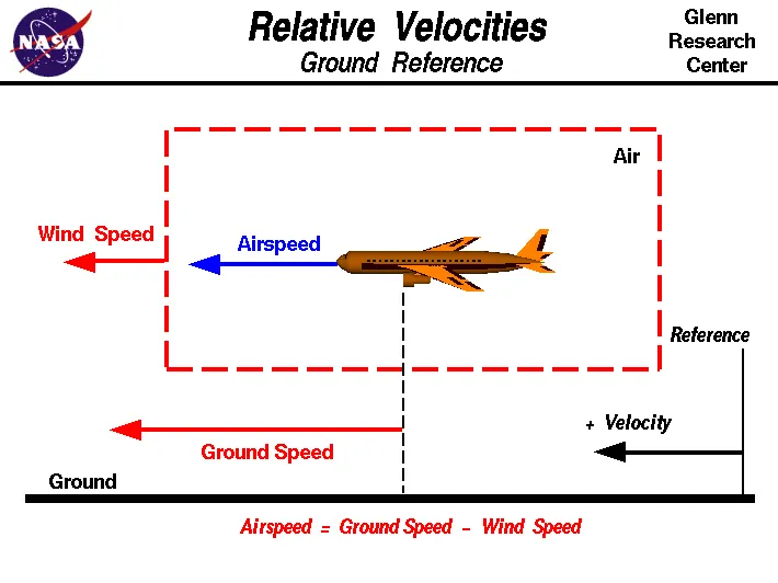
fig(iii) The representation of the relative speed of an aircraft
While ground speed is the aeroplane’s speed relative to the surface of the Earth, airspeed – at least true airspeed – is its speed relative to the air it is flying in.
As mentioned above, true airspeed is simply the speed at which an aircraft is moving relative to the air it is flying in. As such, it’s also the speed at which the air is flowing around the aircraft’s wings.
Ground speed, on the other hand, is the aircraft’s speed relative to the ground. One thing that should be noted here is that it's horizontal rather than vertical speed – an aircraft climbing completely vertically would have a ground speed of zero.
In other words, while airspeed is what determines whether there is enough airflow around an aircraft to make it fly, ground speed is what determines how fast an aircraft will get to its destination.
Also, there is an effect of wind speed on the ground speed. Ground speed is simply the sum of airspeed and wind speed. If the aircraft is flying in the same direction as the wind is blowing, the aircraft experiences tailwind, and its ground speed is higher than its airspeed. On the other hand, if the wind is blowing against the direction the aircraft is travelling in, the aircraft experiences headwind, and its ground speed is lower than its airspeed.
---------------------------------------------------------------------------------------------------------------------------------------------------------------------------------------------------
(3) Why is it not recommended to use aircraft engine power to move it on the ground at Airport?
Answer:-
The aircraft can use its own engine to move on the ground at the airport, but it is not recommended due to the following reasons:
- Some aircraft can reverse using a variable pitch prop or thrust reversing on turbofans but generally reversing is done via pushback tractors. Blasting jet reversers blows debris in the crowded gate area creating foreign object damage hazard for adjacent aircraft, gate equipment or terminal waiting area glass windows.
- The constraint of space unless the aircraft is in a location where it is unwise to taxi under aircraft power.
- For bigger aircraft, the fuel consumption is too high and it cost a lot for just a taxi operation.
- The power used to do so create a lot of noise and fumes.
- It risks foreign object damage to the engines and unnecessary jet blasts.
- Modern planes are huge. It is difficult to navigate such gigantic structures through limited space. An A380 is eight stories high. The pilots won't be able to see anything directly in front of them or anything behind the wings.
- Not every ground crew is certified to start or taxi the aircraft. A tow vehicle is safer, easy to certify ground crews to hook up and tow and the unstarted engine is safer.
Actually, Pushback is for moving the aircraft backwards from the gate, and towing or taxing is the procedure to move the aircraft. These machinery are called as aircraft tugs. Aircraft tugs are real modern marvels, moving aircraft weight hundreds of tons all day, every day. A true pushback tug aims to allow the operator to have excellent visibility of the attaching mechanism between aeroplane and tug.
While moving the aircraft in the reverse direction by applying the forward thrust, care must be taken because the reverse thrust is unsafe when stopped or at low speed. This is because the nose may lift, dropping the tail on to the Tarmac. The cause is the engines being at some considerable height from the ground and the aircraft centre of gravity being just ahead of the main (rear) wheelset. Additionally, once moving backwards, if the aircraft’s own brakes are used, the same can happen, i.e., the plane can sit on its tail.
---------------------------------------------------------------------------------------------------------------------------------------------------------------------------------------------------
(4) How an aircraft is pushed to the runway when it's ready to take off?
Answer:-
The aircraft is pushed to the runway using a taxing vehicle. Taxiing refers to the movement of an aircraft on the ground, under its own power. The aircraft moves on wheels. An aeroplane uses taxiways to taxi from one place on an airport to another; for example, when moving from a terminal to the runway.
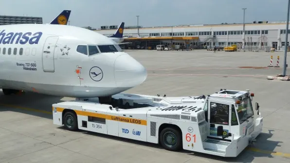
fig (iv) Pushback tug for taxing operation
The aircraft always moves on the ground following the yellow lines, to avoid any collision with the surrounding buildings, vehicles or other aircraft. The taxiing motion has a speed limit. Before making a turn, the pilot reduces the speed further to prevent tire skids. The aircraft that are landing or taking off have higher priority. The other aircraft have to wait for these aircraft before they start or continue taxiing.
The thrust to propel the aircraft forward comes from its propellers or jet engines. Steering is achieved by turning a nose wheel or tail wheel/rudder; the pilot controlling the direction travelled with their feet. The use of engine thrust near terminals is restricted due to the possibility of jet blast damage. This is why the aircraft is pushed back from the buildings by a vehicle before they can start their own engines for taxing. The taxing operation is carried out by an operator sitting in the truck, but some companies are developing a completely autonomous vehicle for the same operation.
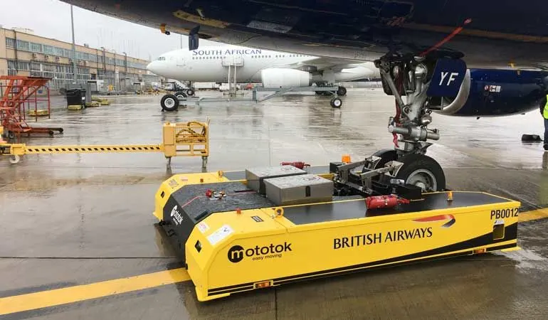
fig (v) Newly developed pushback tug with complete autonomously operated
---------------------------------------------------------------------------------------------------------------------------------------------------------------------------------------------------
(5) Learn about take-off power, tyre design, rolling resistance, tyre pressure, brake forces when landing.
Answer:-
Take-off Power:-
Takeoff is the phase in which an aerospace vehicle leaves the ground and becomes airborne. For aircraft that take off horizontally, this usually involves starting with a transition from moving along the ground on a runway. For a given aircraft, the takeoff speed is usually dependent on the aircraft weight; the heavier the weight, the greater the speed needed. The power required to achieve the take-off speed is Take-off Power.
Trye Design:-
An aircraft tyre is designed to withstand extremely heavy loads while landing, take off, taxing, and parking. The number of wheels required for aircraft increases with the weight of the aircraft, as the weight of the aeroplane needs to be distributed more evenly. They help to absorb the shock of landing and provide cushioning. It also provides the necessary traction for braking and stopping of an aircraft.
Construction:
Carcass plies are used to form the tire. They are sometimes called casing plies. An aircraft tyre is constructed for the purpose it serves.
- They support the weight of an aircraft while it is on the ground.
- It also provides the necessary traction for braking and stopping of an aeroplane.
- Tyre also helps to absorb the shock of landing and provide cushioning the roughness of takeoff, roll-out, and taxi operations.
Unlike an automobile or truck tyre, it does not have to carry a load for a long period of continuous operation. However, an aircraft tyre absorbs the high impact loads of landing, and also it’s operating at high speeds for a short time when required.
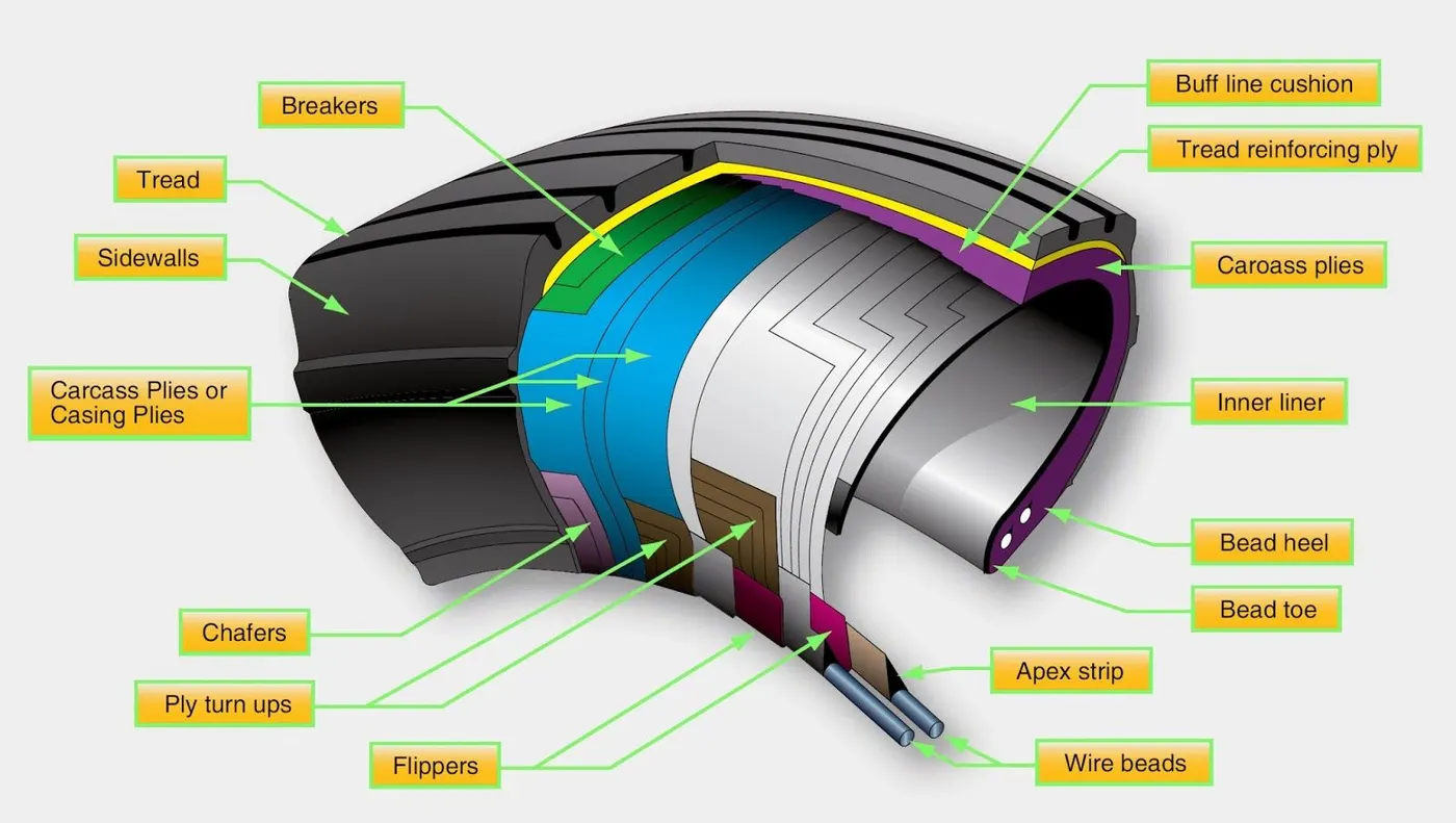
fig(vi) The cut section of the aircraft tyre showing different terminology
Tread: The tread is made of rubber mixed with other additives to obtain the desired level of toughness, durability, and resistance to wear. The tread pattern is designed to aircraft operational requirements, with the ribbed tread design used widely due to its good traction under varying runway conditions.
Sidewall: The sidewall is a protective layer of rubber that covers the outer casing ply. It extends from the tread edge to the bead area.
Tread Reinforcing Ply: One or more layers of fabric that strengthens and stabilizes the tread area for high-speed operation. It also serves as a reference for the buffing process when tires retreat.
Buff Line Cushion: The buff line cushion is made of rubber compound to enhance the adhesion between the tread reinforcing ply and the breakers or casing plies. It is of sufficient thickness to allow for the removal of the old tread when the tire has retreated.
Breakers: Breakers are reinforcing plies of rubber-coated fabric placed under the buff line cushion to protect casing plies and strengthen and stabilize the tread area. They are considered an integral part of the casing construction.
Casing Plies: Alternate layers of rubber-coated fabric (running at opposite angles to one another) provide the strength of the tire.
Wire Beads: Hoops of high tensile strength steel wire that anchor the casing plies and provide a firm mounting surface on the wheel. The outer edge of the bead that fits against the wheel flange is called the bead heel. The inner bead edge is called the bead toe.
Apex Strip: A wedge of rubber affixed to the top of the bead bundle.
Flippers: Layers of rubberized fabric that help anchor the bead wires to the casing and improve the durability of the tire.
Ply Turn ups: The casing plies are anchored by wrapping them around the wire beads, thus forming the ply turnups.
Chafer: A protective layer of rubber and/or fabric located between the casing plies and wheel to minimize chafing.
Liner: In tubeless tires, the liner is a layer of low permeability rubber that acts as a built-in tube and restricts gas from diffusing into the casing plies. In tube-type tires, a thinner liner is used to prevent tube chafing against the inside ply.
Rolling Resistance:-
It is defined as the resisting force created by the motion of the trye with respect to ground. Usually, the rolling resistance will occur at the take-off & landing of the aircraft on the runway.
Tyre Pressure:-
Aircraft tires generally operate at high pressures, up to 200 psi (14 bar; 1,400 kPa) for airliners, and even higher for a business jet. The main landing gear on the Concorde was typically inflated to 232 psi (16.0 bar), whilst its tail bumper gear tires were as high as 294 psi (20.3 bar).
Tests of airliner aircraft tires have shown that they are able to sustain pressures of maximum 800 psi (55 bar; 5,500 kPa) before bursting. During the tests, the tires have to be filled with water, to prevent the test room being blown apart by the energy that would be released by gas when the tire bursts.
Aircraft tires are usually inflated with nitrogen to minimize expansion and contraction from extreme changes in ambient temperature and pressure experienced during flight. Dry nitrogen expands at the same rate as other dry atmospheric gases (normal air is about 80% nitrogen), but common compressed air sources may contain moisture, which increases the expansion rate with temperature.
Brake force when landing:-
Stopping a 200-tonne aircraft landing at 180 mph requires a lot of braking force. To do this, the aircraft have brake units on each wheel powered by the hydraulics system. An electrical signal is sent from the flight deck to hydraulic actuators near the main landing gear. Here, hydraulic fluid at 3,000 pounds per square inch is used to force the brake unit against the wheel, thus slowing it down.
In addition to the brakes, there are two other systems which help slow the aircraft down on landing. The spoilers and the reverse thrust.
Spoiler: The large panels on the top of the wings raise up on touch down are the called the spoilers as they literally spoil the airflow over the wing. This dumps any remaining lift the wings are generating, allowing the wheels to take all the weight and achieve maximum efficiency from the brakes.
Reverse Thrust: The final part of the braking process comes from reverse thrust. Just after the aircraft have touched down, the pilot pulls the two levers on top of the thrust levers to engage the reverse thrust, a sort of “reverse gear” for jet engines.
---------------------------------------------------------------------------------------------------------------------------------------------------------------------------------------------------
(6) With necessary assumptions, calculate the force and power required to push/pull an aircraft by a towing vehicle.
Answer:-
For calculating the force and power to push/pull an aircraft by a towing vehicle, we consider only the rolling resistance force and the aerodynamic drag force and neglecting the Hill climbing force and acceleration force.
Rolling resistance is the resisting force created by the motion of the trye with respect to ground. It is given by:
`F_(rr) = mu_(rr)*m*g`
Where,
`mu_(rr)` = Co-efficient of rolling resistance
`m` = mass of the body in `kg`
`g` = Gravitational acceleration in `m/sec^2`
Aerodynamic drag force cause due to the boundaries of the body and the air near to the boundary are experiencing the higher velocity compared to the air surrounding it. It is given by:
`F_(ad) = 1/2 * rho*A*C_d*V^2`
Where,
`rho` = Aire density in `kg/m^3`
`A` = frontal area in `m^2`
`C_d` = Co-efficient of drag
`V` = Velocity in `m/sec`
Considering an example of Airbus A380 using MATLAB code:
%Force & Power calculation to pull/push Airbus A380

clear all
close all
clc

%Input variables
Cr = 0.02;        %Rolling resistance
g = 9.81;         %Gravitational Acceleration | m/sec^2
rho = 1.22;       %Density | kg/m3
A = 20;          %Frontal area | m^2
Cd = 0.25;        %Co-efficient of drag
V = 9.6;           %Velocity of the vehicle | m/sec
Ma = 573795;      %Weight of aircraft | kg
Mt = 50000;       %Weight of Pushback tug | kg

%Force & Power calculation
Frr = Cr*(Ma+Mt)*g;            %Rolling resistance force
Fad = 0.5*rho*A*Cd*(V^2);      %Aerodynamic drag force
Ft = Frr + Fad;                %Total Traction force
Power = Ft*V/1000;             %Power

%Printing the values in command window
fprintf ('Rolling resistance force = %0.2f N n',Frr)
fprintf ('Aerodyanamic drag force = %0.2f N n',Fad)
fprintf ('Power required by a towing vehicle = %0.2f kW n',Power)

%End od program
Results:
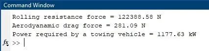
The power required by the towing vehicle is 1177.63 kW.
---------------------------------------------------------------------------------------------------------------------------------------------------------------------------------------------------
(7) Design an electric powertrain with the type of motor, it’s power rating, and energy required to fulfil aircraft towing application. Estimate the duty cycle range to control the aircraft speed from zero to highest. Make all required assumptions. Prepare a table of assumed parameters. Draw a block diagram of the powertrain.
Answer:-
The parameters assumed for designing this vehicle is taken from online references:
| Sr No | Assumed Parameters | Assumed Values |
| 1 | Weight of the Aircraft (kg) | 573795 |
| 2 | Weight of the Towing vehicle (kg) | 50000 |
| 3 | Rolling resistance co-efficient of aircraft | 0.004 |
| 4 | Rolling resistance co-efficient of towing vehicle | 0.001 |
| 5 | The velocity of the aircraft while towing (m/s2) | 9.6 |
| 6 | The density of air medium(rho)(kg/m3) | 1.22 |
| 7 | The frontal area of the Aircraft (m2) | 20 |
| 8 | Co-efficient of drag of the aircraft | 0.02 |
| 9 | Towing vehicle gear ratio 'G' (for high torque output) | 11 |
| 10 | Towing vehicle tyre radius 'r' (m) | 0.635 |
| 11 | Operational time of the towing for one cycle (hr) | 0.25 |
| 12 | Battery armature voltage (V) | 350 |
| 13 | Battery armature current (A) | 350 |
| 14 | Motor terminal voltage for full power output (V) | 630V @ motor terminal |
| 15 | Power converters used | Bidirectional DC-DC Boost converter |
| 16 | Maximum duty ratio for achieving full power (%) | 70 |
Power rating: As per the above calculation, we found that power produced by the motor is 1177.63 kW.
Energy requirement:
Assuming the operational time of the towing truck is around 15 minutes for one cycle;
15 minutes = 0.25 hour
The energy required to fulfil the aircraft towing application is given by
Energy (kWh) = Power(kW)*Time(h) = 1177.63*0.25
Energy(kWh) = 294.4 kWh
Therefore the battery must be able to store the energy of 294.4 kWh and should deliver the energy throughout the runtime in order for the motor to produce the 77.89 kN-m of instantaneous torque.
Motor selection:
Here we have selected a Brushless DC motor type that has a power rating of 128.6 kW and with the gear ratio and transmission, it should be able to deliver 77.89 kN-m of torque.
The battery armature voltage (V) = 350 V (assume)
The battery armature current (A) = 350 A (assume)
For getting the maximum power output from the motor (126.8 KW), the voltage applied to the motor terminals must be 700V (assume) at the motor's positive and negative terminals.
Power Converters:
Here we use a DC-DC boost converter to upscale the voltage level from the battery to the required level so that when supplied to the motor we can get the desired power output from the motor. The bidirectional DC-DC converters find applications in places where battery charging, regenerative braking, and backup power are required. The power flow in a bidirectional converter is usually from a low voltage end such as a battery or a supercapacitor to a high voltage side and is referred to as boost operation. During regenerative braking, the power flows back to the low voltage bus to recharge the battery. As a backup power system, the bidirectional DC-DC converter facilitates the safe operation of the vehicle when ICEs or electric drives fail to drive the motor. The boost converter converts the 350V of the armature voltage to a high voltage level of 900 V.
Speed control of the vehicle:
The electric vehicle uses power from the battery source to drive the motor and then further to drive the wheels in order to move the vehicle. The speed and torque generated from the motor are very important to drive the vehicle as per the Driver's desire. If we connect the battery directly to the motor the motor will spin with a speed and torque characteristics which will be based on the full power of the battery voltage. We do not require full power in all the driving conditions so we need to adopt a power controller between the battery and the motor so that the motor speed may be controlled by the driver to drive the vehicle as desired. For controlling the vehicle power we use the soft switching operation technique here. The amount of power can be controlled by changing the duty cycle value. Considering the losses we take 70 % of the duty cycle to deliver the maximum power of the motor
Motor terminal voltage = Armature voltage * Duty cycle = 900 * 0.7 = 630 V
With 70% Duty Cycle the Voltage at Motor Terminals = 630 V, Which gives the full power with all the gearings, instantaneously. Thus by varying the Duty Cycle value the speed of the vehicle is controlled.
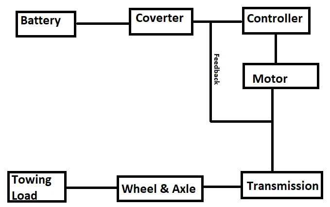
fig(vii) The simple block diagram of the powertrain
Results:
- The reference Aircraft taken here is the commercial aircraft build and so our designed towing pushback tug is a heavy-duty operational vehicle.
- The power requirements are calculated for the particular load to be pushed/pulled and to achieve this power at the motor output, the motor type and its voltage at the terminals are discussed.
- Then the power converters are used to upscale the battery armature voltage to the desired high voltage value so that the motor may spin at full power and required torque can be achieved using a Bidirectional DC-DC Converter.
- Finally, the speed control of the vehicle is done with Switching techniques where the duty cycle adjustment can change the motor speed from minimum to maximum.
---------------------------------------------------------------------------------------------------------------------------------------------------------------------------------------------------
REFERENCE:
- https://en.wikipedia.org/wiki/Aircraft_gross_weight
- https://en.wikipedia.org/wiki/List_of_airliners_by_maximum_takeoff_weight
- https://aviation.stackexchange.com/questions/12956/what-are-What%20are%20different%20types%20of%20weights%20of%20an%20aircraft?
- https://www.knaviation.net/airspeed-and-ground-speed/
- https://www.grc.nasa.gov/www/k-12/airplane/move.html#:~:text=Airspeed%20is%20the%20vector%20difference,speed%20and%20the%20wind%20speed.&text=On%20a%20perfectly%20still%20day,less%20than%20the%20ground%20speed.
- https://en.wikipedia.org/wiki/Pushback#:~:text=In%20aviation%2C%20pushback%20is%20an,called%20pushback%20tractors%20or%20tugs.&text=A%20pushback%20is%20therefore%20the,aircraft%20away%20from%20the%20gate.
- https://news.schiphol.com/how-the-turnaround-process-works/
- https://en.wikipedia.org/wiki/Aircraft_tire#:~:text=Aircraft%20tires%20generally%20operate%20at,294%20psi%20(20.3%20bar).
- https://en.wikipedia.org/wiki/Takeoff
- https://www.aviationhunt.com/aircraft-tyre-construction/
- https://www.aviationpros.com/gse/pushbacks-tractors-utility-vehicles/product/10025557/tld-a380-towbarless-tractor