Project-1: Powertrain for aircraft in runways
1. Search and list out the total weight of various types of aircrafts.
The different terms represent different weights or masses. For each flight, the weights are taken into account for several reasons.
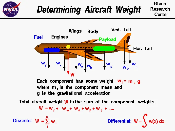
- Manufactre's Empty Weight (MEW) →">→
- Also called Manufacturer's Weight Empty (MWE) or Licensed Empty Weight. It is the weight of the aircraft "as built" and includes the weight of the structure, power plant, furnishings, installations, systems and other equipment that are considered an integral part of an aircraft. This excludes any baggage, passengers, or usable fuel.
-
Zero Fuel Weight (ZFW)→">→
-
This is the total weight of the airplane and all its contents (including unusable fuel), but excluding the total weight of the usable fuel on board. As a flight progresses and fuel is consumed, the total weight of the airplane reduces, but the ZFW remains constant. Maximum zero fuel weight (MZFW) is the maximum weight allowed before usable fuel and other specified usable agents (engine injection fluid, and other consumable propulsion agents) are loaded.
-
Operating Empty Weight (OEW) →">→
-
(Roughly equivalent to basic empty weight on light aircraft). It is the basic weight of an aircraft including the crew, all fluids necessary for operation such as engine oil, engine coolant, water, unusable fuel and all operator items and equipment required for flight but excluding usable fuel and the payload.
- Payload →">→
- It is the carrying capacity of an aircraft. It includes cargo, people, extra fuel. In the case of a commercial airliner, it may refer only to revenue-generating cargo or paying passengers.
- Maximum Takeoff Weight (MTOW) →">→
- This is the maximum weight at which the pilot of the aircraft is allowed to attempt to take off.
- Regulated Takeoff Weight (RTOW) →">→
- Depending on different factors (e.g. flap setting, altitude, air temperature, length of runway), RTOW or maximum permissible takeoff weight varies for each takeoff. It can never be higher than MTOW.
- Maximum Landing Weight (MLW) →">→
- This maximum weight at which an aircraft is permitted to land. The following image depicts takeoff weight components.
- Maximum Ramp Weight (MRW)→">→
- also called maximum taxi weight (MTW). It is the maximum weight authorized for maneuvering (taxiing or towing) an aircraft on the ground.
- Aircraft Gross Weight →">→
- It is the total aircraft weight at any moment during the flight or ground operation. This decreases during flight due to fuel and oil consumption.
Types of Aircraft →">→
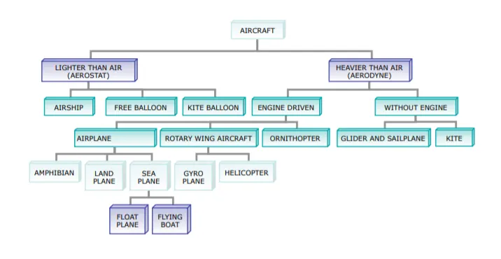
- Aircraft:
- An aircraft is a vehicle that can fly by gaining support from the air. It counters the force of gravity by using either static lift or by using the dynamic lift of an airfoil, or in a few cases the downward thrust from jet engines. Common examples of aircraft include airplanes, helicopters, airships (including blimps), gliders, paramotors, and hot air balloons.
- The human activity that surrounds aircraft is called aviation. The science of aviation, including designing and building aircraft, is called aeronautics. Crewed aircraft are flown by an onboard pilot, but unmanned aerial vehicles may be remotely controlled or self-controlled by onboard computers. Aircraft may be classified by different criteria, such as lift type, aircraft propulsion, usage, and others.
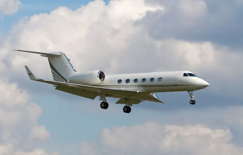
Types of aircraft:
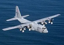
Turboprop Aircraft:
The turboprop aircraft has one or more gas turbine engines. They are both connected to a gearbox that turns the propellers. This is contrary to the pistons or jet engines that are found in the other types of small aircraft. The turboprop airplanes are usually much bigger than the piston aircraft that they resemble and can fly at much higher altitudes of 35,000 feet. They are well suited to flying for 600 to 1000 miles in a single flight, and a much cheaper option to private jets.
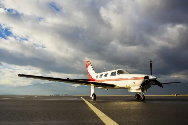
Piston Aircraft:
These resemble turboprop aircraft but are much smaller. They have one more piston-powered engine that is connected to the propellers. They are also incapable of flying at the high altitudes that the turboprop aircraft fly at (15,000 feet) and can cover much less distance (300 to 400 miles). The typical piston aircraft can seat around one to six people, which seats are in rows of two. Piston aircraft don’t need long runways to fly and don’t need traffic control towers to navigate.
Jets:
Jet planes are known for their speed and power as compared to normal aircraft. They achieve maximum efficiency at high speeds and so can even go supersonic (faster than the speed of sound). Jet aircraft can usually go at around Mach 0.8 (609 miles per hour), and fly at altitudes of 49,000 feet. Jets were first developed in 1928 in England but were perfected in Germany in 1936 when Ernst Heinkel led the construction of the first jet plane.
Narrow-body aircraft:
Narrow-body aircraft is also known as single-aisle aircraft since they allow seating in a single row and have a cabin with a diameter of about three to four meters. This allows for up to 6 abreast seating and down to 2-abreast.
The highest seating capacity is 295 passengers. This only occurs with the Boeing 757-300. The size of the fuselage in a narrow-body airplane allows passengers to stand and walk around, but not with much autonomy. There is also room for lavatories and for flight attendants to attend to the travelers. Many executive airlines utilize narrow airplanes with luxury interiors like the Airbus 318 and the Airbus 319.
Wide Body Airlines:
Widebody airliners allow for a lot more room and movement within them as suggested by the name. The cabin diameter in the plane is near five to six meters. The passenger flights are usually pretty comfortable with passengers able to move around comfortably and enough room to accommodate two passenger aisles. There are up to eleven seats abreast.
The seating capacity can go up to 850 passengers in a typical wide-body plane and be at a minimum of 200 passengers. The largest wide-body jets are almost 6 meters wide and accommodate even more passengers. There are several facilities inside including cargo holds, lavatories, and flight attendants.
Airbus:
Airbus is a European manufacturer of airplanes that are registered in the Netherlands but has its services registered in other countries such as France, Germany, and Spain. It has been operational since 1970 and deals in large planes that can carry a large number of passengers. The first Airbus was the A300, and it was the world’s first twin-aisle aircraft with twin engines. A smaller version of the A300, the A310, came into existence shortly after. Variations of the aircraft exist such as the A318, A319, A350, A220, and the A321. These range from airplanes with 2 engines and 2 aisles, to 4 engines and double-deckers with twin aisles.
Military aircraft:
Military aircraft is a term that refers to fixed-wing or rotary-wing aircraft that are operated by a legal or insurrectionary armed service. This could include a noncombatant aircraft, a marine or navy aircraft, or belonging to the air force. This could be meant for surveillance, an attack, or transport.
Total Weight of various types of aircraft:
Antonov An-225 Mriya:
The Antonov An-225 Mriya is a strategic airlift cargo aircraft that was designed by the Antonov Design Bureau in the Ukrainian SSR within the Soviet Union during the 1980s. It is powered by six turbofan engines and is the heaviest aircraft ever built, with a maximum takeoff weight of 640 tonnes (710 short tons; 630 long tons). It also has the largest wingspan of any aircraft in operational service. A second airframe with a slightly different configuration was partially built. Its construction was halted in 1994 because of lack of funding and interest, but revived briefly in 2009, bringing it to 60–70% completion. On 30 August 2016, Antonov agreed to complete the second airframe for Airspace Industry Corporation of China as a prelude to commencing series production.
The Antonov An-225 was initially developed as an enlargement of the Antonov An-124 to transport Buran-class orbiters. The only An-225 airplane was completed in 1988. After successfully fulfilling its Soviet military missions, it was mothballed for eight years. It was then refurbished and reintroduced, and is in commercial operation with Antonov Airlines, carrying oversized payloads. The air lifter holds the absolute world record for an airlifted single-item payload of 189,980 kg (418,830 lb), and an airlifted total payload of 253,820 kg (559,580 lb). It has also transported a payload of 247,000 kg (545,000 lb) on a commercial flight.
Boeing 747-8F:
The 747-400 and earlier versions had proven to be a very popular freighter, carrying around half of the world's air freight. To maintain this position, Boeing designed a freight variant of the 747-8, named the 747-8 Freighter or 747-8F. The company launched the freighter version on November 14, 2005. The 747-8F is the initial model to enter service. As on the 747-400F, the upper deck is shorter than passenger models; the 18-foot-3+1⁄2-inch (5.575 m) stretch is just before and just aft of the wing. 747-8 Freighter was designed with a 975,000 lb (442 t) maximum take-off weight with a payload capability of 308,000 lb (140 t) and a range of 4,390 nmi (8,130 km). Four extra pallet spaces were created on the main deck, with either two extra containers and two extra pallets, or three extra pallets, on the lower deck. The 747-8F is expected to have a 16% lower ton-mile operating cost than the 747-400F and offer a slightly greater range.
Cargolux and Nippon Cargo Airlines were the first customers for the 747-8, placing orders for the freighter variant in November 2005. The firm configuration of the aircraft was finalized in October 2006. Major assembly of the aircraft began on August 8, 2008, and the aircraft first left Boeing's Everett factory on November 12, 2009. The first aircraft was delivered on October 12, 2011, to Cargolux. Boeing announced that initial 747-8F operators had achieved a 1-percent reduction in fuel burn over projections at its six-month service mark.
In June 2015, Boeing predicted new orders for the 747-8F based on its projections of a 4.7% annual increase in air cargo demand.
Ilyushin-II-96M:
The Il-96M is a stretched variant of the Il-96-300. It features a 10 m (30 ft) fuselage stretch, is 15 tonnes (33,000 lb) heavier, is fitted with Western-style avionics, and is powered by four Pratt & Whitney PW2337 engines with a thrust rating of 165 kN (37,000 lbf). Range with 312 passengers in a three-class configuration or 92 tonne (203,000 lb) payload is about 10,400 km (5,600 nmi). This turned it into a true—but vastly more capable—Il-86 successor. Development on the M/T variant stalled when the US Export-Import Bank suspended talks on financing the engines and avionics, following pressure from Boeing. The dispute was later settled following an Aeroflot order for ten Boeing 737-400s—placed in April 1997 in a deal worth US$440 million that was granted a tax exemption by the Russian government. Nevertheless, the financing was blocked again when four Boeing 767-300ERs also ordered by Aeroflot were not included in the accorded exemption.
Lockheed L-1011 Tristar:
The TriStar's internal Lockheed model number is L-093. The TriStar was manufactured in Lockheed facilities in Burbank and Palmdale, California.
Lockheed discovered fairly early on that the TriStar suffered from higher than estimated structural weight, engine weight, and specific fuel consumption. To rectify this problem and to meet performance guarantees, Lockheed developed a structural kit that allowed maximum takeoff weight (MTOW) to be increased on production aircraft from 409,000 to 430,000 pounds (186,000 to 195,000 kg). However, the weight problems affected the weight and desirability of early production L-1011-1 aircraft, known as Group 1 (serial numbers 1002 through to 1012).
Group 1 aircraft have an OEW of 252,700 pounds (114,600 kg), about 12,700 pounds (5,800 kg) higher than later aircraft, while Group 2 aircraft (serial numbers 1013 through 1051) have an OEW of 247,000 pounds (112,000 kg), some 4,700 pounds (2,100 kg) lower. These aircraft, in general, also have a different center of gravity envelopes with the forward center of gravity limit on the early aircraft being more restrictive at higher gross weights. Groups 1 and 2 aircraft (serial numbers 1002 to 1051) are upgradeable only to -50 or -150 specifications, although the Group 1 aircraft (up to serial number 1012) still maintain their operating disadvantages. All L-1011-1 aircraft from serial number 1052 onwards are Group 3 aircraft and are fully upgradeable to all variants up to -250 specifications.
Well, to summarize the weights of the above-mentioned types of aircraft is as follows.
|
Type |
Payload (kg) |
MTOW |
|
Antonov An-225 |
240,000 |
640,000 |
|
Boeing 747-8F |
139,706 |
447,700 |
|
Ilyushin-II 96M |
203,000 |
270,000 |
|
Lockheed L-1011 Tristar |
146,200 |
195,000 |
2. Is there any difference between ground speed and air speed?
Ground Speed:
Ground speed is the horizontal speed of an aircraft relative to the Earth’s surface. It is vital for accurate navigation to the destination that the pilot has an estimate of the ground speed that will be achieved during a flight. An aircraft diving vertically would have a ground speed of zero. The information displayed to passengers through the entertainment system of airline aircraft usually gives the aircraft ground speed rather than airspeed.
Ground speed can be determined by the vector sum of the aircraft's true airspeed and the current wind speed and direction; a headwind subtracts from the ground speed, while a tailwind adds to it. Winds at other angles to the heading will have components of either headwind or tailwind as well as a crosswind component.
An airspeed indicator indicates the aircraft's speed relative to the air mass. The air mass may be moving over the ground due to wind, and therefore some additional means to provide position over the ground is required. This might be through navigation using landmarks, radio-aided position location, inertial navigation system, or GPS. When more advanced technology is unavailable, an E6B flight computer may be used to calculate ground speed. Ground speed radar can measure it directly. Ground speed is quite different from airspeed. When an aircraft is airborne the ground speed does not determine when the aircraft will stall, and it doesn't influence the aircraft's performance such as rate of climb.
AirSpeed:
Airspeed is the speed of an aircraft relative to the air. Among the common conventions for qualifying airspeed are indicated airspeed ("IAS"), calibrated airspeed ("CAS"), equivalent airspeed ("EAS"), and true airspeed ("TAS").
Indicated airspeed is simply what is read on an airspeed gauge connected to a pitot-static system; calibrated airspeed is indicated airspeed adjusted for pitot system position and installation error, and equivalent airspeed is calibrated airspeed adjusted for compressibility effects. True airspeed is equivalent airspeed adjusted for air density and is also the speed of the aircraft through the air in which it is flying. Calibrated airspeed is typically within a few knots of indicated airspeed, while equivalent airspeed decreases slightly from CAS as aircraft altitude increases or at high speeds.
With EAS constant, true airspeed increases as aircraft altitude increases. This is because air density decreases with higher altitude.
The measurement and indication of airspeed are ordinarily accomplished onboard an aircraft by an airspeed indicator ("ASI") connected to a pitot-static system. The pitot-static system comprises one or more pitot probes (or tubes) facing the on-coming airflow to measure pitot pressure (also called stagnation, total, or ram pressure) and one or more static ports to measure the static pressure in the airflow. These two pressures are compared by the ASI to give an IAS reading.
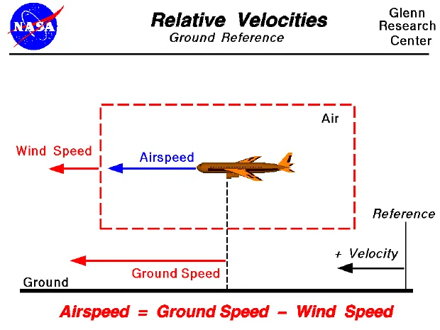
Difference between ground speed and airspeed:
Ground speed is how fast an airplane's shadow would move across the land. If there's a strong wind pushing an aircraft, that's reflected in the ground speed. Airspeed, in contrast, is how fast an airplane is really flying strictly under its own power, which is calculated by subtracting the wind speed from the ground speed. If the wind is blowing in the same direction as the aircraft then the airspeed will be less than the ground speed.
Ground speed determines how fast an aircraft will get to its destination but the airspeed determines whether there is enough airflow around an aircraft to make it fly.
3.Why it is not recommended to use aircraft engine power to move it on the ground at the Airport?
The movement of an aircraft on the ground under its own power is called Taxiing. But to move the aircraft from hanger to the runway, the term used is the taxiways.
Although many aircraft are capable of moving in backward using reverse thrust, as a result, the jet blast or prop wash might cause damage to the terminal building or equipment.
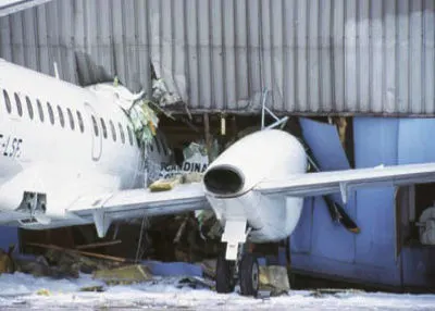
The risks which may arise from engine ground running relate to the potential for loss of control of the aircraft by those persons occupying the pilot seats in the flight deck. In most cases, such persons will be maintenance personnel holding specific company-issued approval for the required tasks. The consequences of loss of control during taxi or towing are the same as apply to these operations generally and this article is concerned only with the risks arising from the static running of one or more aircraft engines. Unwanted consequences from such static running are mainly related to those arising from the unintended movement of the aircraft during engine running - effectively a loss of control especially during high power engine running. Damage can occur to the aircraft itself, other aircraft nearby, or to airside structures. In addition, there is a risk of injury to ground support personnel who may be in relatively close proximity to the aircraft.
Although most aircraft are capable of moving themselves on the ground, it is not typically done due to the following reasons,
- The jet blast from the engines can damage the terminal building and nearby equipment. It can even throw away people standing nearby.
- Engines can blow sand and debris.
- Engines can suck in sand and debris which can cause serious damage to the engine.
- It is easier for the truck driver to see the surroundings better than the pilot sitting in the cockpit with limited windows.
- The pushback truck driver knows the airport better than the pilot.
- The plane engines are very loud. This noise can add up substantially when multiple planes are moving around the airport. It won't be a pleasant experience for people sitting inside the terminal, as most people don't even like the sound of powerful motor-bikes.
- It saves fuel.
- Modern planes are huge. It is difficult to navigate such gigantic structures through limited space. An A380 is eight stories high. The pilots won't be able to see anything directly in-front of them or anything behind the wings.
Actually Pushback is for moving the aircraft backwards from the gate, and towing or taxing is the procedure to move the aircraft. These machineries are called as aircraft tugs. Aircraft tugs are real modern marvels, moving aircraft weight hundreds of tons all day, every day. A true pushback tug aims to allow the operator to have excellent visibility of the attaching mechanism between airplane and tug.
while moving the aircraft in the reverse direction by applying the forward thrust, care msut be taen because reverse thrust is unsafe when stopped or at low speed. This is because the nose may lift, dropping the tail on to the Tarmac. The cause is the engines being at some considerable height from the ground and the aircraft centre of gravity being just ahead of the main (rear) wheel set. Additionally, once moving backwards, if the aircraft’s own brakes are used, the same can happen, i.e., the plane can sit on its tail.
4.How an Aircraft is pushed to the runway when it's ready to take off?
Aircraft is pushed back from the airport gate by vehicles called tugs or tractors. This is called Pushback. The tug might be directly attached to the plane's nose gear with a tow bar, or could be a "wheel-lift" tug. These tugs cradle the nose gear, then lift it up before moving the plane. That gives the tug driver control over the plane's direction during pushback. New taxi technologies are appearing, like pilot-controlled tugs, and electric motors mounted to the plane's landing gear. Both promise to save fuel and reduce airport noise.
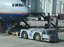
Pushbacks at busy aerodromes are usually subject to ground control clearance to facilitate ground movement on taxiways. Once clearance is obtained, the pilot will communicate with the tractor driver (or a ground handler walking alongside the aircraft in some cases) to start the pushback. To communicate, a headset may be connected near the nose gear. Pushback tractors use a low-profile design to fit under the aircraft's nose. For sufficient traction, the tractor must be heavy, and most models can have extra ballast added.
Since the pilots cannot see what is behind the aircraft, steering is done by the pushback tractor driver and not by the pilots. Depending on the aircraft type and airline procedure, a bypass pin may be temporarily installed into the nose gear to disconnect it from the aircraft's normal steering mechanism.
Once the pushback is completed, the tow bar is disconnected, and any bypass pin removed. The ground handler will show the bypass pin to the pilots to make it clear that it has been removed.The pushback is then complete, and the aircraft can taxi forward under its own power.
5.Take off Power, Tyre Design, Rolling Resistance, Tyre Pressure, Brake forces when Landing?
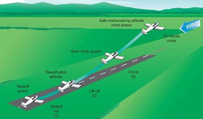
Take-off Power:The amount of power that an engine is allowed to produce for a limited period of time for takeoff. The use of takeoff power is usually limited to 5 min for reciprocating engines and up to 2½ min for gas turbine engines. This may not always be the case.Specifically, with respect to reciprocating engines, it is the brake horsepower developed under standard, sea-level conditions and under the maximum conditions of the crankshaft rotational speed and the engine manifold pressure approved for the normal take-off. It is limited in continuous use to the period of time shown in the approved engine specifications. With respect to gas turbine engines, it is the thrust developed under static conditions at a specified altitude and atmospheric conditions of the rotor shaft rotational speed and gas temperature approved for the normal takeoff. It is limited in continuous use to the period of time shown in the approved engine specifications.
Tyre Design:
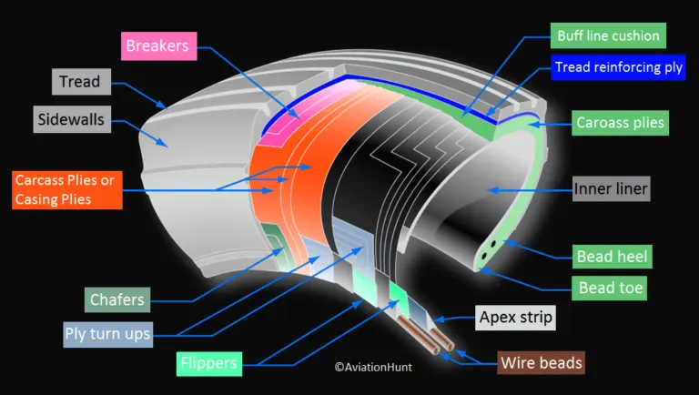
The tires help to absorb the shock of landing and provide cushioning.It also provides the necessary traction for the braking and stopping of an aircraft.
An aircraft tire is designed to withstand extremely heavy loads while landing, take off, taxing, and parking. The number of wheels required for aircraft increases with the weight of the aircraft, as the weight of the airplane needs to be distributed more evenly.
Design:Carcass plies are used to form the tire. They are sometimes called casing plies. An aircraft tire is constructed for the purpose it serves.
- They support the weight of an aircraft while it is on the ground.
- It also provides the necessary traction for the braking and stopping of an airplane.
- Tyre also helps to absorb the shock of landing and provides cushioning for the roughness of takeoff, roll-out, and taxi operations.
Unlike an automobile or truck tire, it does not have to carry a load for a long period of continuous operation. However, an aircraft tire absorbs the high impact loads of landing, and also it’s operating at high speeds for a short time when required.
Aircraft tires are manufactured with tread rubber with conducting compounds to permit earthing of static charges.
Rolling Resistance:
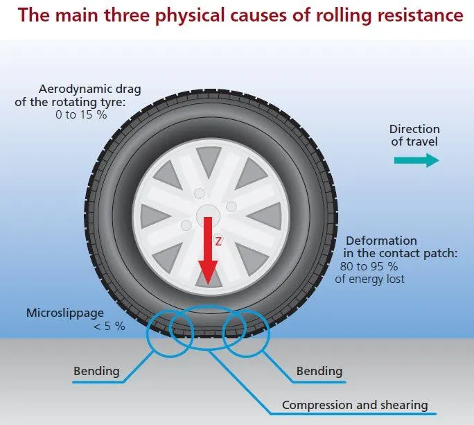
Rolling resistance sometimes called rolling friction or rolling drag is the force resisting the motion when a body rolls on a surface.It is mainly caused by non-elastic effects; that is, not all the energy needed for deformation of the wheel, roadbed, etc.,is recovered when the pressure is removed. Two forms of this are hysteresis losses and permanent (plastic) deformation of the object or the surface. Note that the slippage between the wheel and the surface also results in energy dissipation. Although some researchers have included this term in rolling resistance, some suggest that this dissipation term should be treated separately from rolling resistance because it is due to the applied torque to the wheel and the resultant slip between the wheel and ground,which is called slip loss or slip resistance.
Tyre Pressure:
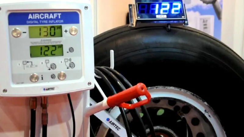
Aircraft tires generally operate at high pressures, up to 200 psi (14 bar; 1,400 kPa) for airliners, and even higher for business jets. The main landing gear on the Concorde was typically inflated to 232 psi (16.0 bar), whilst its tail bumper gear tires were as high as 294 psi (20.3 bar).
Aircraft tires are usually inflated with nitrogen to minimize expansion and contraction from extreme changes in ambient temperature and pressure experienced during flight. Dry nitrogen expands at the same rate as other dry atmospheric gases (normal air is about 80% nitrogen), but common compressed air sources may contain moisture, which increases the expansion rate with temperature.
Landing Brake Forces:
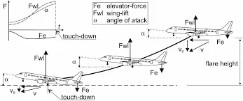
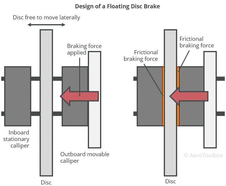
On other aircraft types, the brake units are powered by the hydraulics system. An electrical signal is sent from the flight deck to hydraulic actuators near the main landing gear. Here, hydraulic fluid at 3,000 pounds per square inch is used to force the brake unit against the wheel, thus slowing it down.
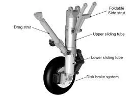
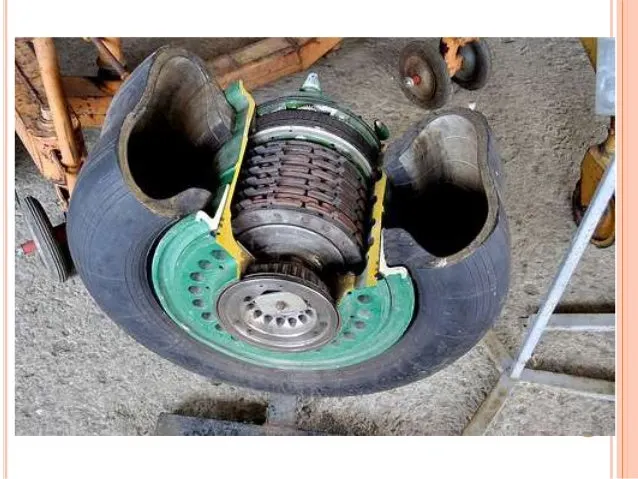
Aircraft Tyre design →">→
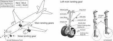
Aircraft wheels are an important component of a landing gear system. With tires mounted upon them, they support the entire weight of the aircraft during taxi, tkeoff, and landing. The typical aircraft wheel is lightweight, strong, and made from aluminium alloy. Some magnesium alloy wheels also exist. Early aircraft wheels were of single piece construction, much the same as the modern automobile wheel.
As aircraft tires were improved for the purpose they serve, they were made stiffer to better absorb the forces of landing without blowing out or separating from the rim. Stretching such a tire over a single piece wheel rim was not possible. A two-piece wheel was developed.
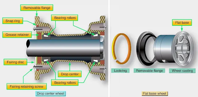
Early two piece aircraft wheels were essentially one-piece wheels wth a removable rim to allow mounting access for the tire.These are still found on older aircraft. Later, wheels with two nearly symmetrical halves were developed. Nearly all modern aircraft wheels are of this two piece construction
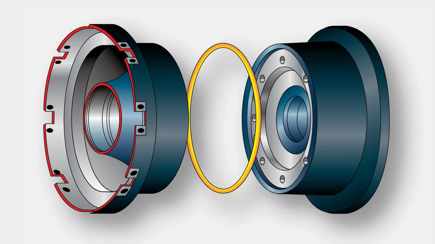
two piece aircraft wheel found on modern airliner →">→
The typical modern two piece aircraft wheel is cast or forged from aluminium or magnesium alloy. The halves are bolted together and contain a groove at the mating surface for an o-ring, which seals the rim sice most modern aircraft utilize tubeless tires. The bead seat area of a wheel is where the tire actually contacts the wheel. It is the critical area that accepts the significat tensile loads from the tire during landing. To strengthen this area during manufacturing, the bead seat area is typically rooled to pre stress it with a compressive stres load. Modern tyres are much more rigid, due to the load bearing requirements, which results in the wheels having to be of two piece construction.
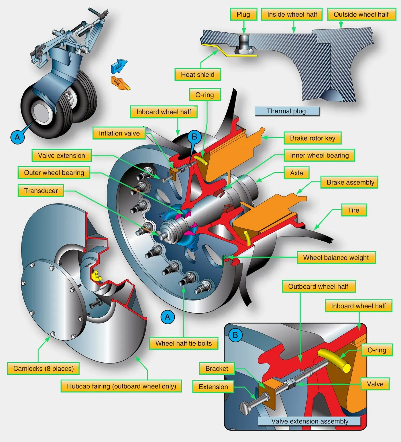
Part B:
6.With necessary assumptions, calculate the force and power required to push / pull an aircraft by a towing vehicle?
Assumption:
Towing Vehicle Mass(kg) - 40000 kg
Mass of the aircraft which act as a payload to the Towing Vehicle(kg) - 150000 kg
Therefore, Total Mass of the towing vehicle(m)=150000+40000 = 190000 kg.
Frontal Area of the vehicle(A) = 18m^2
Speed of the vehicle(v) = 20kmph.
In m/sec;
Speed of the vehicle(v) = 20*5/18 = 5.556m/sec
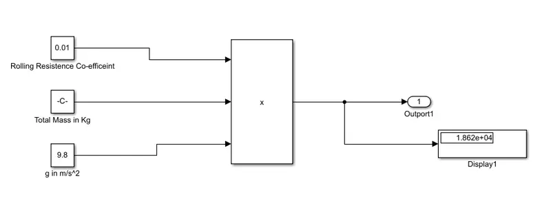
Rolling Resistance Co-efficient(Crr) = 0.01
Now, Rolling Resistance Force(Frr) = C⋅rr m⋅g
=0.01*190000*9.8
= 18,620N.
Similarly, For
Aerodynamic Drag:
Coefficient of Drag for the towing vehicle(Cd_v) = 0.608
Coefficient of Drag for the aircraft(Cd_a) = 0.15
Air Density(ρ) = 1.225kg/m3
Now, Aerodynamic Drag(Fad) = 0.5*(Cd_v + Cd_a)*v^2*ρ*A
= 0.5*(0.608+0.15)*5.556^2*1.225*18
= 257.97N
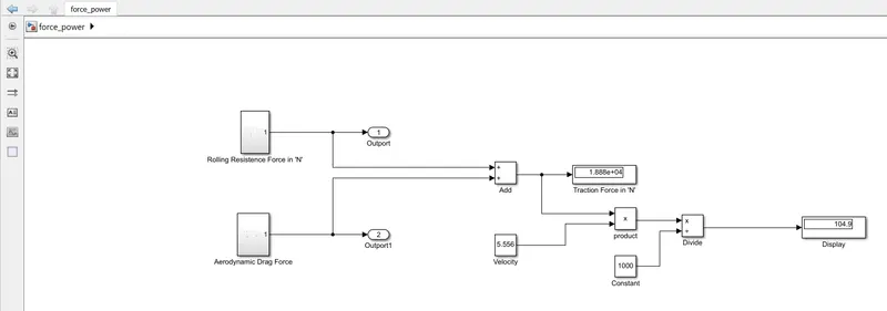
Therefore, Total Force Required to Push/Pull the aircraft by the Towing Vehicle is:
= Frr+ Fad
= 18,620+257.97
= 18,859.97N
Power calculation:
= Frr * V
= 18,859.97 * 5.556
= 104785.993 W
= 104.7 KW.
B. Develop the model for the calculated force and power using Simulink.
- Rolling Resistence Force Calculation:
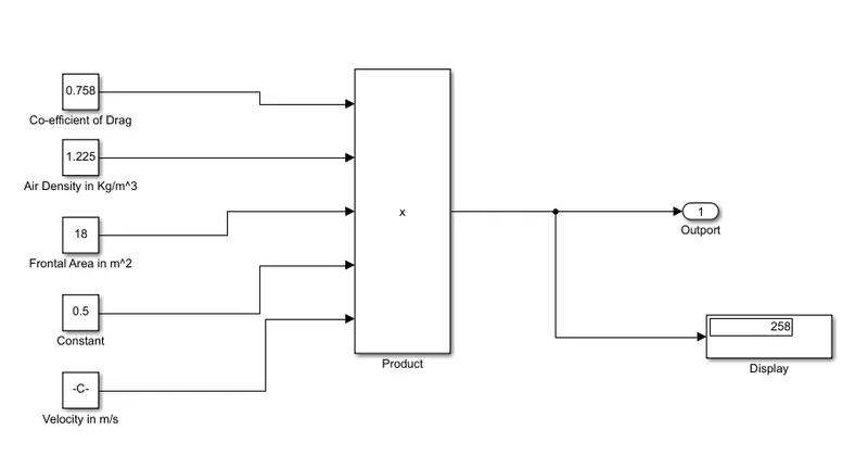
- Aerodynamic Drag Calculation:
- Power Calculation:
7. Design an electric powertrain with type of motor, it’s power rating, and energy requirement to fulfill aircraft towing application in Simulink. Estimate the duty cycle range to control the aircraft speed from zero to highest. Make all required assumptions. Prepare a table of assumed parameters. Draw a block diagram of powertrain.
(Hint :DC7 Block)
B. Also, Design the parameters in excel sheet.
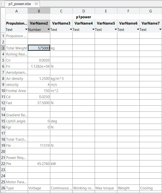
A. Design an electric powertrain with type of motor, it’s power rating, and energy requirement to fulfill aircraft towing application in Simulink. Estimate the duty cycle range to control the aircraft speed from zero to highest. Make all required assumptions. Prepare a table of assumed parameters. Draw a block diagram of powertrain.
Estimation of Duty Cycle:
Based on the calculation done in study 6
The Power Required for towing of the aircraft is 45.26kW.
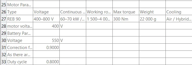
Motor Considred for the drive train is REB 90
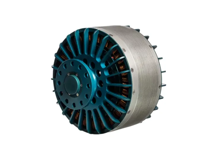
Technical Data:
| Type | Voltage | Continuous / Peak power | Working rotation | Max torque | Weight | Cooling |
| REB 90 | 400–800 V | 60–70 kW / 80 kW | 1 500–4 000 rpm | 300 Nm | 22 000 g |
Air / Hybrid (air + fluid) |
Considering 60kW as continuous power, so the voltage will be 400V
Battery power is considred to be 550v
Duty cycle is given by,[ Vo/Vb]
where Vo is motor required voltage
Vb is battery voltage.
d=400/550⇒0.7272
As there will be losses due to the resistance of FET and Inductance.
Correction factor is considred to be 90%
As there is 10% loss, the voltafge demanded by the motor should be 10% more than required
d=0.7272⋅(1+0.1)=0.799≈0.8
so the voltage demand should be around 440V from the battery.
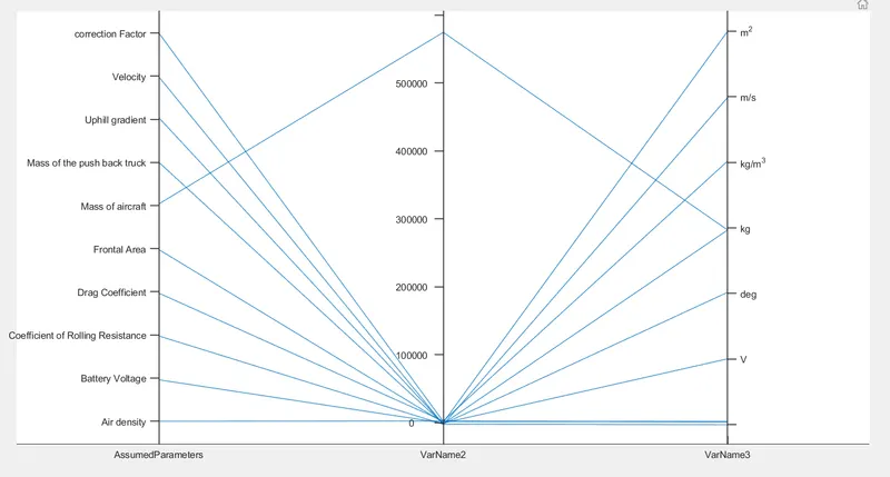
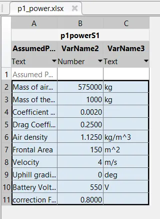
| Assumed Parameters | ||
| Mass of aircraft | 575000 | kg |
| Mass of the push back truck | 1000 | kg |
| Coefficient of Rolling Resistance | 0.002 | |
| Drag Coefficient | 0.025 | |
| Air density | 1.125 | kg/m^3 |
| Frontal Area | 150 | m^2 |
| Velocity | 4 | m/s |
| Uphill gradient | 0 | deg |
| Battery Voltage | 550 | V |
| Correction Factor | 0.8 | |
Block Diagram:
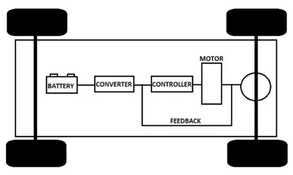
Simulink Model:

Input:
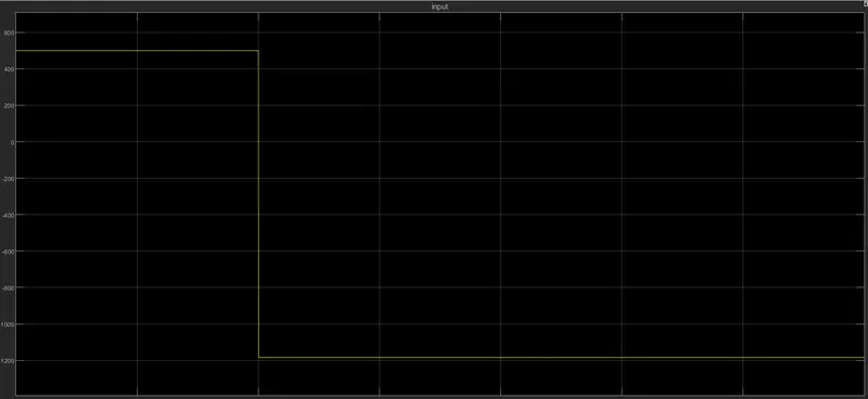
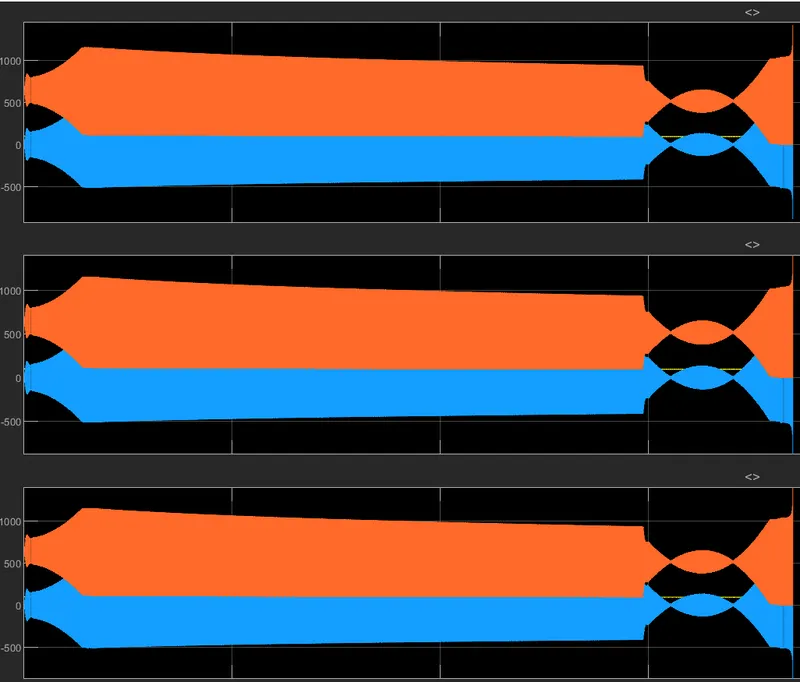
Output:
From the motor:
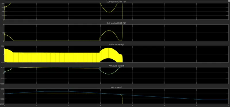
From the Battery:
MATLAB EXCLE SHEET :
OUT-PUT :