Week-6 Challenge: EV Drivetrain
1. Which types of power converter circuits are employed in electric and hybrid electric vehicle?
Electric Vehicles:
An electric vehicle (EV) is a vehicle that uses one or more electric motors or traction motors for propulsion. An electric vehicle may be powered through a collector system by electricity from off-vehicle sources, or may be self-contained with a battery, solar panels, fuel cells or an electric generator to convert fuel to electricity.
Hybrid Electric Vehicles:
A hybrid electric vehicle (HEV) is a type of hybrid vehicles that combines a conventional internal combustion engine (ICE) system with an electric propulsion system. The presence of the electric powertrain is intended to achieve either better fuel economy than a conventional vehicle or better performance. There is a variety of HEV types and the degree to which each function as an electric vehicle (EV) also varies. The most common form of HEV is the hybrid electric car, although hybrid electric trucks (pickups and tractors), buses, boats and aircraft also exist.
Power Electronic Converters: -
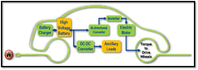
In Electric and Hybrid Electric Vehicles (EV/HEV), the power electronic converters are considered as the key elements that interface their power sources to the drivetrain of the EVs. In order to design highly efficient converters for the EV’s power system, advanced DC/DC and DC/AC converters are required to adapt the output voltage and current levels with high power quality.
The 3 types of converters which are widely used in an Electric Vehicle are:
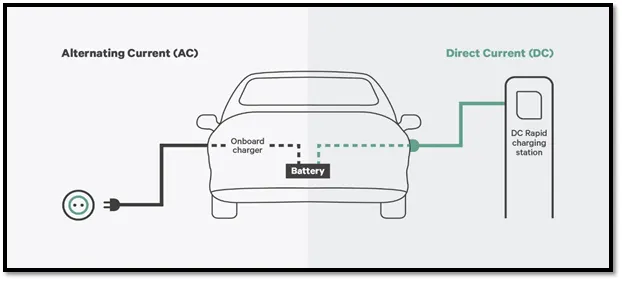
AC – DC Converter (On Board Charger): -
AC to DC converters are most commonly used in Plug-in Hybrid Electric Vehicles (PHEV) & Plug-in Electric Vehicles (PEV). These vehicles get their propulsion power from an external electricity source (charging stations) which is alternating current. The battery needs to be charged using a direct current source. For this purpose, AC to DC converter is employed in a PHEV & PEV.
DC – DC Converter: -
DC-DC converters can be used to interface the elements in the electric power train by boosting or chopping the voltage levels. By introducing DC/DC converters one can choose the voltage variation of the devices and the power of each device can be controlled. The power of the DC/DC converter depends on the characteristics of the vehicle such as top speed, acceleration time from 0 to 100 Km/h, weight, maximum torque, and power profile (peak power, continuous power).
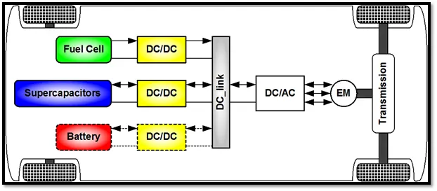
The most common DC/DC converters can be grouped as follows:
Non-isolated converters
The non-isolated converters type is generally used where the voltage needs to be stepped up or down by a relatively small ratio (less than 4:1). And when there is no problem with the output and input having no dielectric isolation. There are five main types of converter in this non-isolated group, usually called the buck, boost, buck-boost, Cuk and charge-pump converters. The buck converter is used for voltage step-down, while the boost converter is used for voltage step-up. The buck-boost and Cuk converters can be used for either step-down or step-up. The charge-pump converter is used for either voltage step-up or voltage inversion, but only in relatively low power applications.
Isolated converters
Usually, in this type of converters a high frequency transformer is used. In the applications where the output needs to be completely isolated from the input, an isolated converter is necessary. There are many types of converters in this group such as Half-Bridge, Full-Bridge, Fly-back, Forward and Push-Pull DC/DC converters. All of these converters can be used as bi-directional converters and the ratio of stepping down or stepping up the voltage is high.
Non-isolated converters:
Buck- A buck converter (step-down converter) is a DC to DC power converter which steps down voltage from its input (supply) to its output (load). It is a class of switched mode power supply (SMPS) typically containing at least two semiconductors a diode and a transistor, although modern buck converters frequently replace the diode with a second transistor used for synchronous rectification and at least one energy storage element, a capacitor,inductor, or the two in combination. To reduce voltage ripple, filters made of capacitors (sometimes in combination with inductors) are normally added to such a converter's output (load-side filter) and input (supply-side filter).
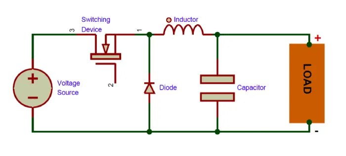
Boost- A boost converter (step-up converter) is a DC to DC converter that steps up voltage from its input (supply) to its output (load). It is a class of switched mode power supply (SMPS) containing at least two semiconductors a diode and a transistor and at least one energy storage element: a capacitor,inductor or the two in combination. To reduce voltage ripple, filters made of capacitors (sometimes in combination with inductors) are normally added to such a converter's output (load-side filter) and input (supply-side filter).
Buck-boost- The buck–boost converter is a type of DC to DC converter that has an output voltage magnitude that is either greater than or less than the input voltage magnitude. It is equivalent to a flyback converter using a single inductor instead of a transformer.
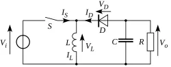
Cuk- The Ćuk converter is a type of buck-boost converter with zero ripple current. Ćuk converter can be seen as a combination of boost converter and buck-converter, having one switching device and a mutual capacitor, to couple the energy.
charge-pump- A charge pump is a kind of DC to DC converter that uses capacitors for energetic charge storage to raise or lower voltage. Charge-pump circuits are capable of high efficiences, sometimes as high as 90–95%, while being electrically simple circuits.
Isolated converters:
Half bridge: A half-bridge converter is a type of DC-DC converter that, like flyback and forward converters, can supply an output voltage either higher or lower than the input voltage and provide electrical isolation via a transformer.
Full bridge: The full-bridge converter adds two additional transistors to the half-bridge converter. This means that four transistors are available to provide power to the output section, so this type of converter is used in power supplies in excess of 1000 Watts. Fig. 1 shows the schematic of the full-bridge converter. Each transistor has a clamping diode connected across its collector-emitter terminals and they are driven alternately in pairs. Transistors T1 and T3 are energized together for one half-cycle, and transistors T2 and T4 are energized together for the other half-cycle. One advantage of the full-bridge converter is that it only requires one capacitor for smoothing the output voltage, whereas the half-bridge converter required two. The full-bridge converter will be used in larger power supplies usually over 1000 Watts. Since this type of converter is more complex, it's normally used in the largest types of power supplies.
Push pull: As the switch-mode power supply has evolved, additional adjustments to the original circuits have been made to get more power from smaller components. This means that the efficiency for the system must be increased. One simple way to do this is to use a center-tapped transformer that utilizes both the top and bottom half-cycles. Fig. 1 shows a schematic of the push-pull converter in which the push-pull converter utilizes a center-tapped transformer for both the primary and secondary windings. The primary winding is controlled by two transistors, which allow one of them to conduct during each half-cycle, so the output is receiving voltage directly through one of them at all times. This means that the efficiency of this configuration is approximately 90%. This allows the overall size for the power supply to be smaller for a comparable power supply whose efficiency is 75% to 80%.
DC – AC Converter (Inverter): -
The DC/AC converter is required to convert the dc power to a suitable ac power for the electrical machine. The power output from battery pack (DC current) is converted using inverter to be used in electric motor (AC current).
References: - https://www.intechopen.com/books/electric-vehicles-modelling-and-simulations/dc-dc-converters-for-electric-vehicles#B14
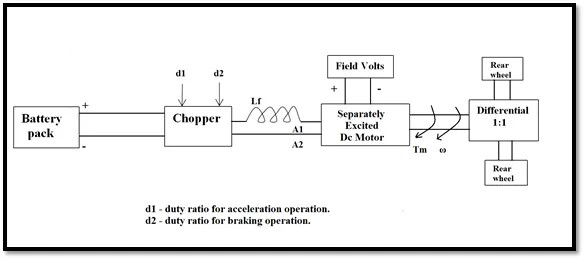
Q2. An Electric Vehicle's powertrain with 72V battery pack in shown in the diagram below. The duty ratio for acceleration operation is 'd1' and for the braking operation the duty ratio is 'd2'.
The other parameters of the electric vehicle is given below,
Motor and Controller Parameters:
Rated Armature voltage=72 V
Rated armature current=400 A
Ra= 0.5Ω, KΦ= 0.7 Volt second
Chopper Switching frequency= 400 Hz
The vehicle speed-torque characteristics are given by the below equation

What is EV steady state speed if duty cycle is 70%?
Given: -
The following input parameters are given: -
Battery pack voltage (V) = 72V
Rated armature current = 400 A
Armature Resistance (Ra) = 0.5Ω
Motor constant (KΦ) = 0.7
Chopper Switching frequency= 400 Hz
Duty Cycle = 70%ω">ω
Solution: -
Vehicle Output Voltage (Vv) is given by: -
Vv = Battery Voltage (V) * Duty Cycle
Vv = 72 * 0.70
Thus, Vehicle voltage = 50.4V
Now, Equation for Vehicle torque is given by: -
Tv=(Vv-ω.K∅)⋅K∅Ra">Tv=(Vv−ω.K∅)⋅K∅Ra
Where;
Tv= Vehicle Torque (N-m)
Vv= Vehicle voltage (Volts)
ω= steady state speed of vehicle (rps)
K∅= Motor constant
Ra= Armature Resistance
Substituting all these values in equation, we get:
Tv=(50.04−0.7⋅ω)⋅0.70÷0.5
Tv=70.56−0.98⋅ω
Tv=24.7+0.0051⋅ω2
Solving these two equations,
70.56−0.98⋅ω=24.7+0.0051⋅ω2
We get a quadratic equation:
0.0051⋅ω2+0.98⋅ω−46.94=0
Since quadratic equation, we get two values of ;
ω= 38.85 rad/s and ω = -230.95 rad/s
We take the positive value;
Steady state speed of vehicle = = 38.85 rad/s or 370 RPM
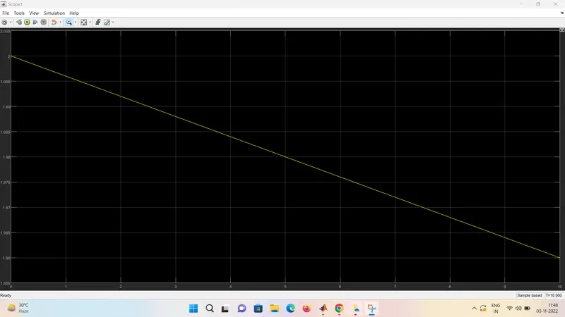
3.Develop a mathematical model of a DC Motor for the below equation using Simulink.
ωω= V/Kϕ -Ra/Kϕ^2 .T
Out-Put Graph Shown Below: Speed Vs Torque
4. Refer to the blog on below topic:
Induction Versus DC brushless motors by Wally Rippel, Tesla
Explain in brief about author’s perspective.
Induction versus DC brushless motor :
According to authors perspective, Firstly he gave the description of DC brushless motor about its parts and specifications and what is called and next description about Induction motor about is component and working of Induction motor. Then he compared the DC brushless and induction which he metioned that 3- phase induction motor can produce output torque and also have an ability to start under the load without any inverter,as of DC brushless motor produces no starting torque when directly connected to fixed frequency utility power and also inverter is needed to start under load.Then he discussed about the limitations of the 3-Phase induction motor they cannot operate from DC; AC is a must. Shaft speed is proportionate to line frequency. Hence, when used with utility power, they are constant speed machines. Finally, when operated from utility power, they have limited starting torque and somewhat limited running peak torque capabilities, when compared to DC type machines.Inverter can be added to 3-Phase induction so that we can supply power from DC source or Battery and also we can get variable speeds and can adjust the frequencies.
Then he discussed as the only main difference between DC brushless and Induction motor is of control code and also the rotor of DC brushless gets less heated at peak torque as that of Induction motor rotor.
Then he discussed about the loses when the motor runs which is the induction machine when operated with a smart inverter has an advantage over a DC brushless machine – magnetic and conduction losses can be traded such that efficiency is optimized. This advantage becomes increasingly important as performance is increased. With DC brushless, as machine size grows, the magnetic losses increase proportionately and part load efficiency drops. With induction, as machine size grows, losses do not necessarily grow. Thus, induction drives may be the favored approach where high-performance is desired; peak efficiency will be a little less than with DC brushless, but average efficiency may actually be better.
He concluded with that DC brushless drives will likely continue to dominate in the hybrid and coming plug-in hybrid markets, and that induction drives will likely maintain dominance for the high-performance pure electrics.
Conclusion:
- Types of power converters used in electric and hybrid electric vehicles explained.
- EV stead speed at 70%duty cycle is 38.915 rad/sec or 371RPM.
- Explained in brief what was author's perspective to Induction VS DC brushless motor.