Project 2 - Modeling of 3 phase Induction Motor Drive
- Model 3 Phase Inverter using Simulink (model the parasitic as well) with a switching frequency of 10Khz using 3 phase Squirrel Cage Induction motor, using V/F method, open loop
Design Parameters:
- Power = 100 HP
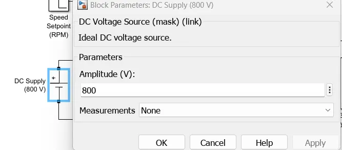
- DC Voltage = 800 V
- Output Voltage = 460 VRMS – line to line
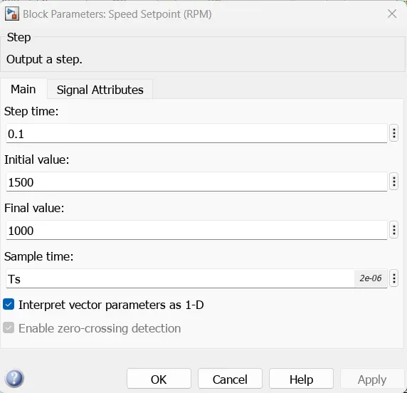
- Initial Speed = 1500 RPM
- Final Speed = 1000 RPM
- Initial Load Torque = 10 Nm
- Final Torque=20 Nm
- Torque Step Time = 0.1 secs
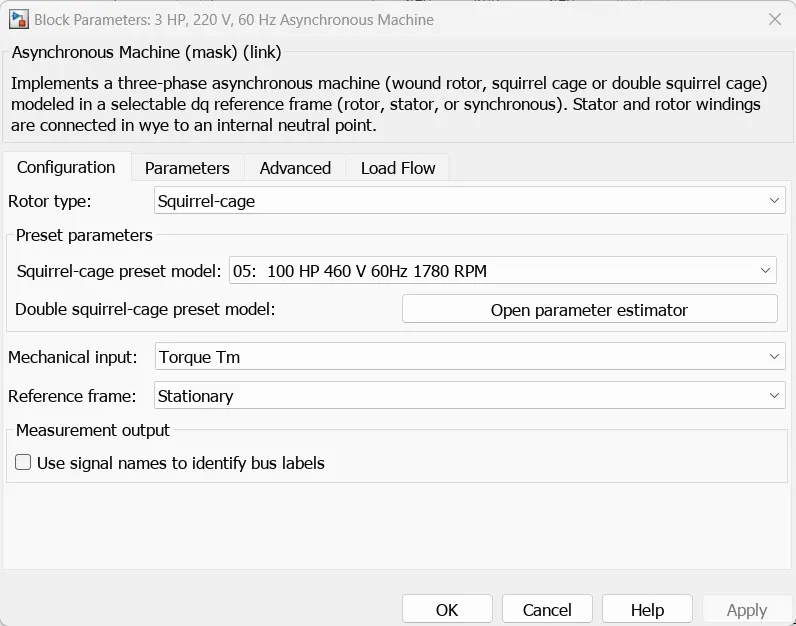
For Induction Motor model – use Asynchronous Machine from Simulink with Squirrel Cage Preset Model – 05 , for 100HP Motor
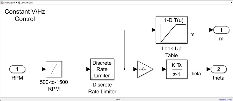
For back emf to speed relation, assume a linear rate from 0.25 to 1, with speed changing from 500 RPM to 2000 RPM
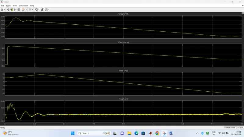
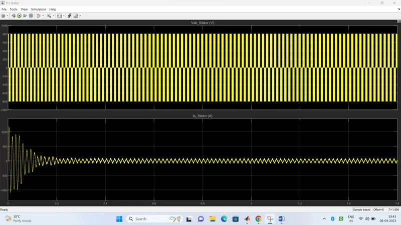
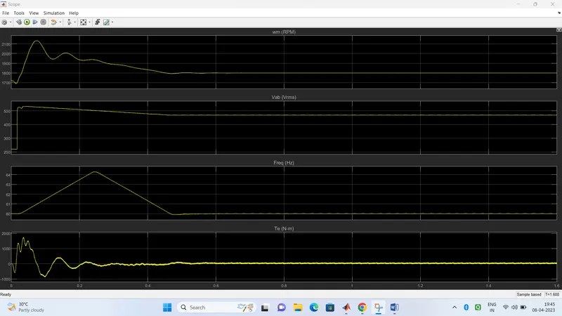
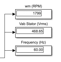
Plot speed, stator voltage (line to line) and frequency.
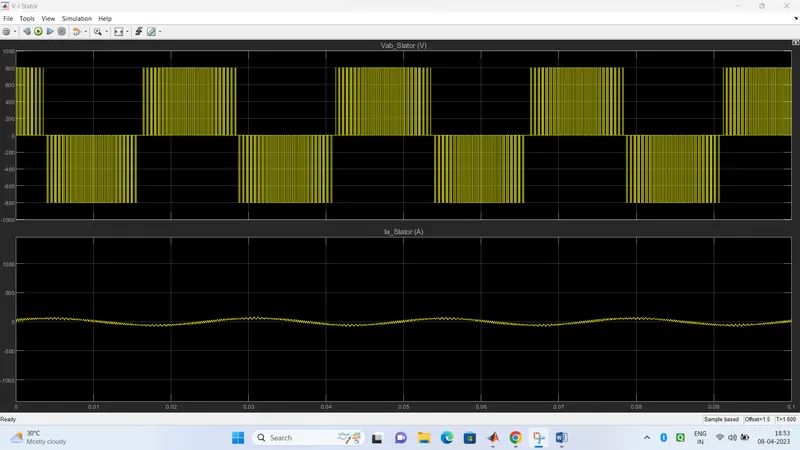
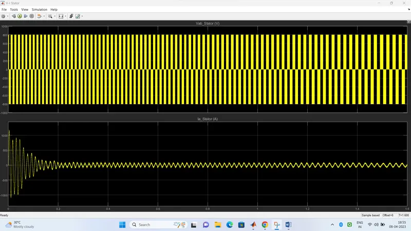
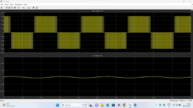
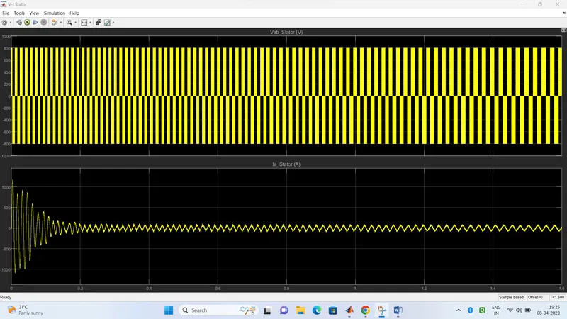
Plot stator line voltage, phase current
initial speed =1500 rpm
final speed=1000 rpm
torque=10 N-M
For Induction Motor model – use Asynchronous Machine from Simulink with Squirrel Cage Preset Model – 05 , for 100HP Motor
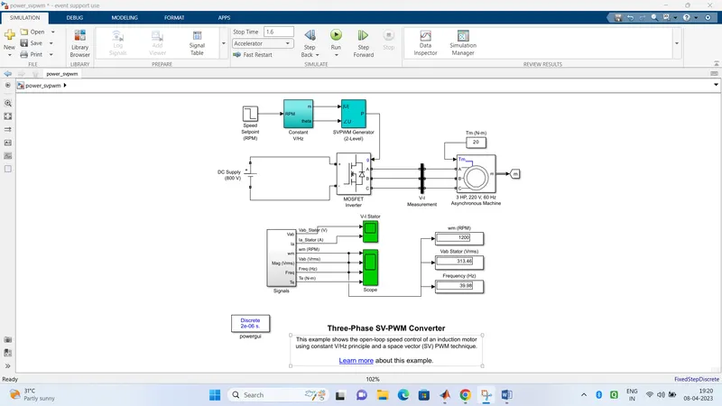
Simulink model:-
Power SVPMW stands for Space Vector Pulse Width Modulation. It is a modulation technique used in power electronics to control the output voltage of a three-phase inverter.
The technique involves generating a space vector diagram that represents the three-phase output voltage of the inverter. The space vector is then split into six smaller vectors, each representing a different switching state of the inverter. By modulating the duty cycle of the switching signals for each vector, the amplitude and phase of the output voltage can be controlled.
Power SVPMW has several advantages over traditional PWM techniques, including higher output voltage quality, higher efficiency, and lower switching losses. It is commonly used in applications such as motor drives, renewable energy systems, and power converters.
In summary, Power SVPMW is a powerful modulation technique used in power electronics to control the output voltage of a three-phase inverter by modulating the duty cycle of the switching signals for each vector.
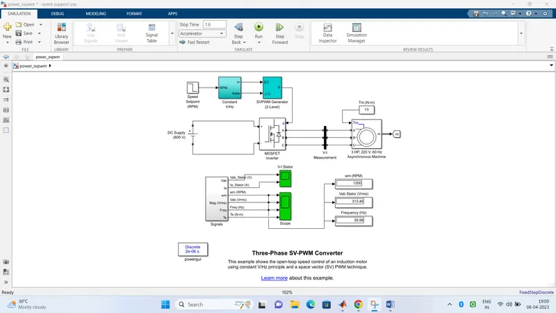
Voltage:-
Step:-
V/HZ control:-
Asynchronous machine:-
Otput waveform:-
V-I STATOR
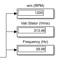
WHEN CONSTANT TORQUE AT 20 N-M:
Otput waveform:-
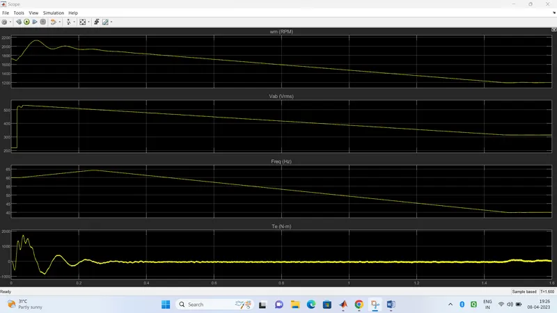
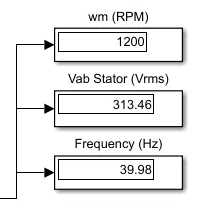
For back emf to speed relation, assume a linear rate from 0.25 to 1, with speed changing from 500 RPM to 2000 RPM
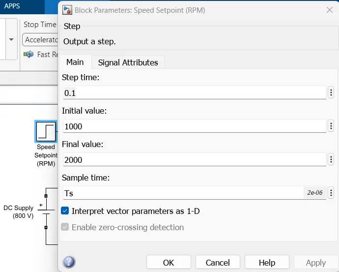
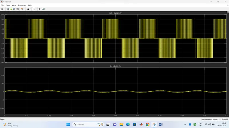
2.Use the 3 phase inductor motor theory to derive the transfer function of 3 phase Induction Motor.
Ans=>
The transfer function of a 3-phase induction motor describes the relationship between the input voltage and the output speed of the motor. To derive this transfer function, we can start with the basic equations governing the behavior of the motor.
The 3-phase induction motor is a type of AC motor that consists of a stator and a rotor. The stator has three windings, typically spaced 120 degrees apart, that are energized with a three-phase AC voltage. This creates a rotating magnetic field that induces a current in the rotor, which in turn produces a torque that drives the motor.
The basic equations that describe the behavior of the motor are:
V_phase = R_phase * I_phase + jX_phaseI_phase ---(1)
where V_phase is the voltage applied to each phase of the motor, R_phase is the resistance of each phase winding, X_phase is the reactance of each phase winding, I_phase is the current flowing through each phase winding, and j is the imaginary unit.
The total torque produced by the motor is given by:
T = (3/2)P(synchronous speed - rotor speed)*R2/S ---(2)
where T is the torque produced by the motor, P is the number of poles in the motor, synchronous speed is the speed of the rotating magnetic field, rotor speed is the speed of the rotor, R2 is the rotor resistance, and S is the slip of the motor.
The slip of the motor is given by:
S = (synchronous speed - rotor speed)/synchronous speed
We can derive the transfer function of the motor by expressing the rotor speed in terms of the input voltage. Assuming a balanced three-phase system, the current in each phase is given by:
I_phase = (1/(jwL_phase))(V_phase - jwM_phaseI_r)
where w is the angular frequency of the AC voltage, L_phase is the inductance of each phase winding, M_phase is the mutual inductance between the stator and rotor windings, and I_r is the rotor current.
Substituting this expression for I_phase into equation (1) and solving for I_r, we get:
I_r = (1/(jwM_phase))[(V_phase/jw*L_phase) - I_phase]
Substituting this expression for I_r into equation (2) and simplifying, we get:
T = (3/2)PR2S[(V_phase/jwL_phase)/((jwM_phase)(synchronous speed - (V_phase/jwL_phase)/((jw*M_phase) + R2))))] ---(3)
Dividing both sides of equation (3) by the input voltage V_phase, we get the transfer function of the motor:
T/V_phase = (3/2)PR2S/((jwL_phase)((jwM_phase)/(synchronous speed - (V_phase/jwL_phase)/((jwM_phase) + R2))))
Simplifying this expression, we get:
T/V_phase = K/(1 + jwTau)
where K is a constant, w is the angular frequency of the AC voltage, and Tau is a time constant given by:
Tau = (L_phase*(jwM_phase + R2))/(jwL_phase*(synchronous speed - (V_phase/jwL_phase)/((jwM_phase) + R2)))
This is the transfer function of the 3-phase induction motor, which describes the relationship between the input voltage and the output speed of the motor.
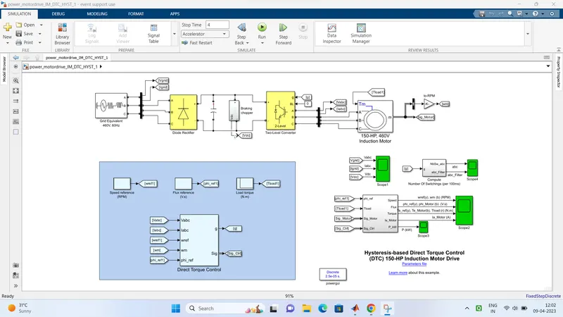
3. Model 3 phase induction motor with a 3 phase inverter using Direct Torque control using an Average Model, Implement both torque and flux control to achieve desired power.
Design Parameters:
- Initial Speed = 0 RPM
- Flux Target = 2.5 webers
- DC Voltage = 500 V;
- Fundamental Frequency = 60 Hz
- Speed Step Time = 0.01 secs
- Determine fundamental speed based upon fundamental frequency
- Determine the switching sequence for direct torque control
- Moment of Inertia = 0.1 Kgm^2
- Load Torque Initial = 0 Nm
- Final Load Torque = 50 Nm
- Torque Step Time = 0.03 secs
Motor Parameters: (Create an Average Model)
- Stator Resistance = 0.5 Ohms
- Rotor Resistance = 0.2 Ohms
- Stator Leakage Inductance = 20 mH
- Rotor Leakage Inductance = 10 mH
- Magnetizing Inductance = 200 mH
- Number of Poles = 4
- Torque to Speed
DTC motor drive:-
DTC is emerging technique for controlling PWM inverter -fed induction motor IM drives. it allows the precies and quick control of the IM flux and torque without calling of complex control algoritham.
To implement both torque and flux control to achieve the desired power, we need to control the stator flux and the electromagnetic torque of the motor. This can be done using two control loops: one for the stator flux and the other for the electromagnetic torque. The control loops use the measured values of the stator currents, stator voltages, and rotor speed to control the motor.
The following steps can be followed to implement DTC using an average model for a three-phase induction motor with a three-phase inverter:
-
Determine the motor parameters: We need to determine the motor parameters such as the stator resistance, rotor resistance, leakage inductance, magnetizing inductance, and the number of poles.
-
Calculate the average values of the motor variables: We need to calculate the average values of the stator voltages, stator currents, and flux in each phase. This can be done using the measured values of the voltage and current in each phase.
-
Calculate the electromagnetic torque: The electromagnetic torque can be calculated using the following equation:
Te = 3/2 * p * (Ld - Lq) * iqs * ids
where Te is the electromagnetic torque, p is the number of poles, Ld and Lq are the direct and quadrature-axis inductances, and iqs and ids are the stator currents in the quadrature and direct axes, respectively.
- Calculate the stator flux: The stator flux can be calculated using the following equation:
ψs = sqrt(ψsd^2 + ψsq^2)
where ψsd and ψsq are the direct and quadrature-axis fluxes, respectively.
-
Control the stator flux: We need to control the stator flux to achieve the desired power. This can be done using a proportional-integral (PI) controller that regulates the stator current in the direct axis (ids). The PI controller adjusts the magnitude and phase of the stator current to control the stator flux.
-
Control the electromagnetic torque: We need to control the electromagnetic torque to achieve the desired power. This can be done using a PI controller that regulates the stator current in the quadrature axis (iqs). The PI controller adjusts the magnitude and phase of the stator current to control the electromagnetic torque.
-
Generate the switching signals for the inverter: Once the desired stator current in the direct and quadrature axes is obtained, the switching signals for the inverter can be generated. The switching signals determine the switching states of the inverter switches.
-
Implement the control algorithm: Finally, the control algorithm can be implemented in a microcontroller or a digital signal processor. The microcontroller or the DSP reads the measured values of the stator currents, stator voltages, and rotor speed, and calculates the switching signals for the inverter. The inverter switches are then controlled using the switching signals to regulate the stator current and the electromagnetic torque.
Simulink model:-
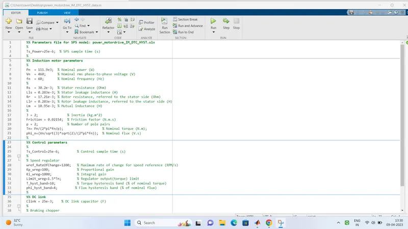
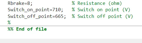
M.File:
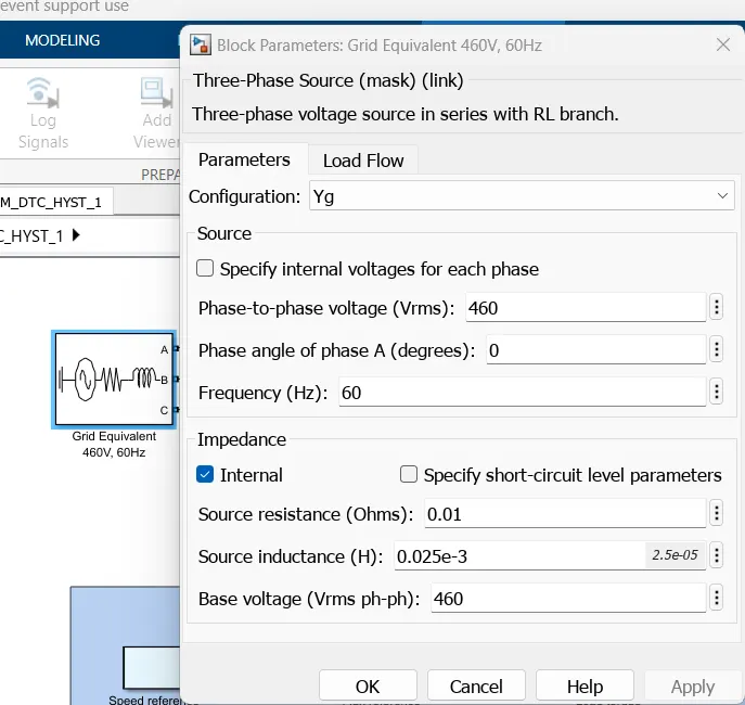
Three phase ac source:-
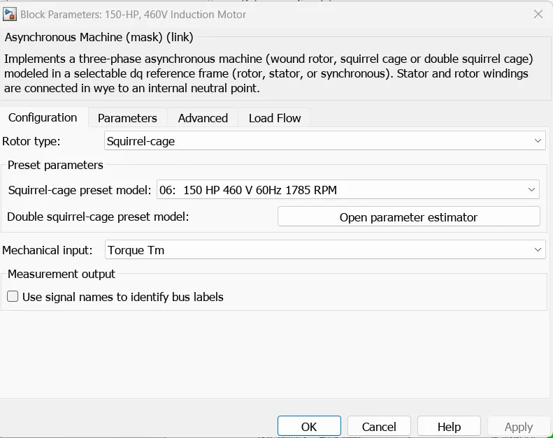
Asynchronous motor:-
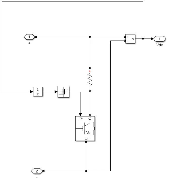
Braking choper:-
Results:-
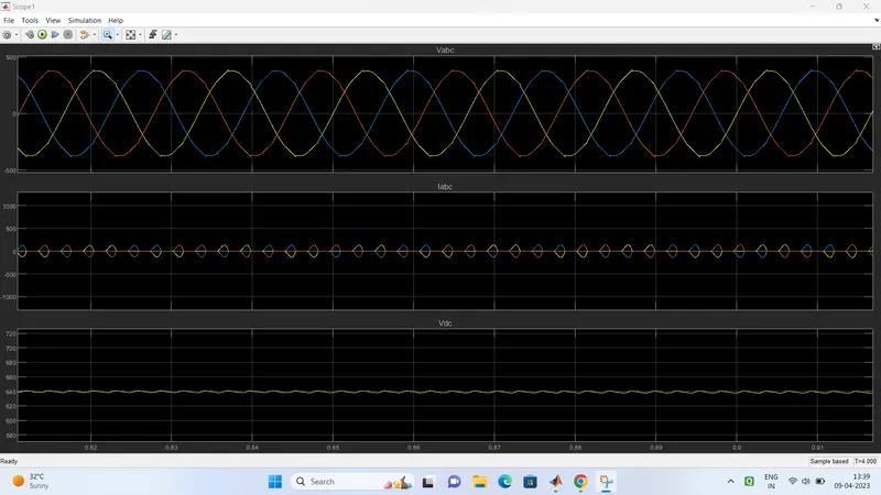
1. Vabc,Iabc and Vdc
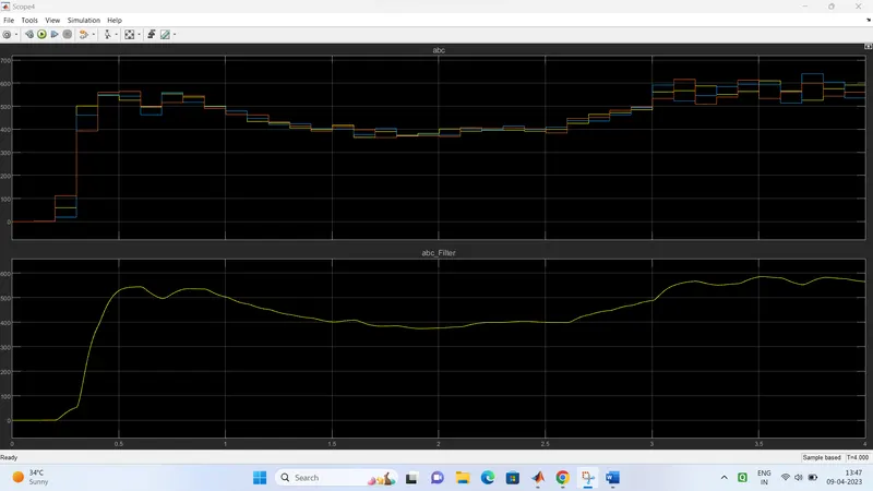
abc,and abc_filter:
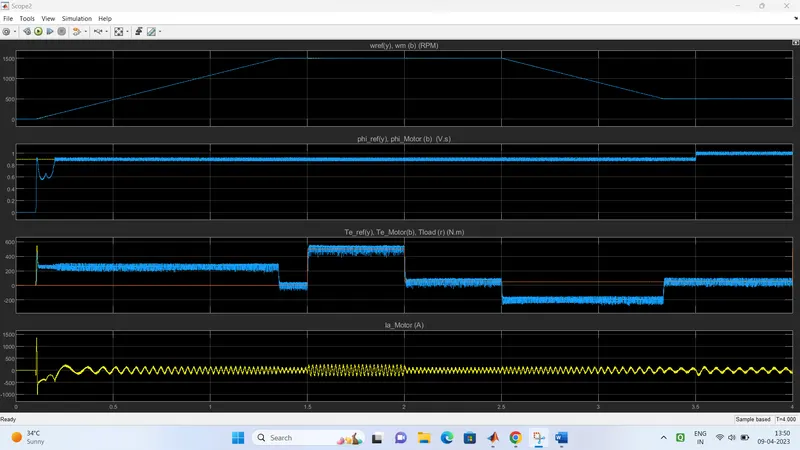
Conclusion:
In summary, to model a three-phase induction motor with a three-phase inverter using DTC, we need to use an average model and control the stator flux and the electromagnetic torque of the motor using two control loops. The control algorithm can be implemented in a microcontroller or a digital signal processor to regulate the motor.