Week - 4
1) WORKING PRINCIPLE OF A WASHING MACHINE :
A washing machine by spinning at 800-1600 rpm helps soap and dirt with it to leave the surface of the cloth via centrifugal force and into outlet pipes hence utilizing centrifugation to both clean and partially dry the clothes loaded in it.Thus
Processes are electrically controlled,such as drum,valves,pump,motor and heating.The Valve Open again and the dirty water
drains out of the drums.The Pump works to help get rid of the water. The valve lets clean water in again into the drums.
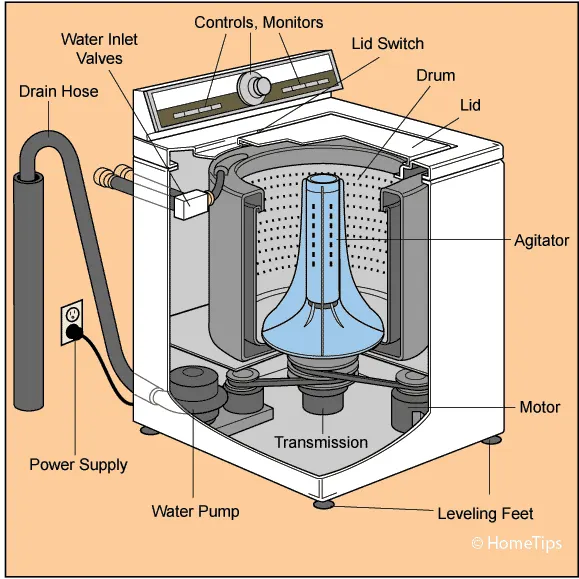
Components of washing machine :
The components of a washing machine that are very important in understanding the working principle of a washing machine is :
Agitator: An agitator is a spindle that is affixed to the centre of the wash drum of an automatic washing machine. The agitator is usually equipped with a fan or vane, and it turns during the machine’s wash cycle to move clothes through the water and, ideally, remove dirt from them.
Drain Pipe: All the dirty water from your wash is pumped out of the machine through the drain pipe.
Motor: As we know that washing machines (domestic) run on a single-phase AC supply and the motor is of a single-phase AC series type which is also called a universal motor. But let us tell you that most domestic washing machines have two motors, one is spinning and the other is used for the drain.
Printed Circuit Board (PCB): A washing machine circuit board is a printed circuit board (PCB)—a board that contains the electrical parts to control machines—that often acts as the brain of a washing machine. Almost every function performed by a washing machine is controlled by a circuit board. The board on ordinary washing machines only tells the washing machine when to fill water or when to wash clothes, but complex washing machines normally will have more advanced boards. Without a circuit board, most washing machines would not be able to function.
Programmer: The programmer used for a washing machine is an important element of the control circuit, responsible for the choice of operation modes. It is one of the most important components that differentiate automatic machines from conventional machines.
Tub: The washing machine consists of two steel tubs. The inner tub is what holds the clothes. It has an agitator in the middle, and the sides are punched with holes so that when the tub spins, the water can drain. The outer tub, which seals in all the water, is attached to the body of the washer. Since the inner tub vibrates and vibrates during the wash cycle, it must be fitted in such a way that it can move around without bumping into other parts of the machine.
Water Inlet Control Valve: Its main responsibility is to manage the ingress of water into your washing machine. The water inlet valve on your washing machine is the part that connects the two water hoses to the machine, and it controls the flow of both hot and cold water.
Water pump: The motor driving the pump can reverse direction. It spins one way when the washer is running the was cycle and recirculates the direction, and it spins another way around when the washer is doing the spin cycle and draining the water.
Timer: It helps to set the wash time for your clothes, which can be set manually or automatically.
Detergent dispenser: detergent dispenser is an important thing in the washing machine. It is used in the washing machine to distribute the appropriate amount of detergent or fabric softener to the drum per cycle.
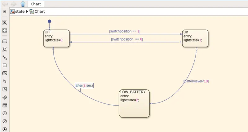
State Flow:
Stateflow is generally used to specify the discrete controller in the model of a hybrid system where the continuous dynamics (i.e., the behavior of the plant and environment) are specified using Simulink.
Specific applications for Stateflow include:
- Mode logic, where each discrete mode of a system is represented by a state.
- Fault management, where the Stateflow chart is used to control how the system responds to faults and failures within a system.
- Task scheduling, where the Stateflow chart is used to schedule when specific tasks occur, either within the Stateflow chart or within the overall Simulink model.
CONTROL LOGIC OF A WASHNIG MACHINE:
It Checks for the extent of dirt and grease,the amount of soap and water to add,direction of spin,and
so on.The machine rebalances washing load to ensure correct spinning.Else,it reduces spinning speed if an imbalance is detected.
Even distribustion of washing load reduces spinning noice.
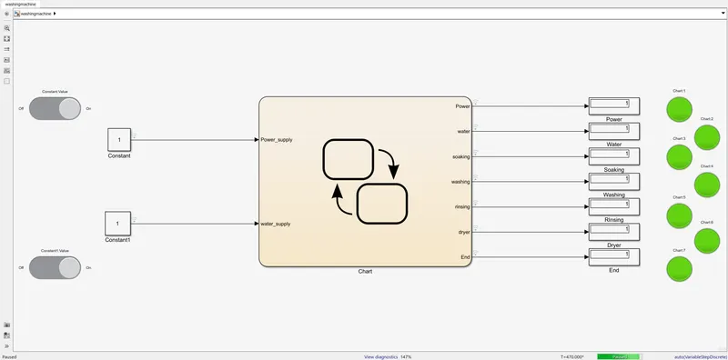
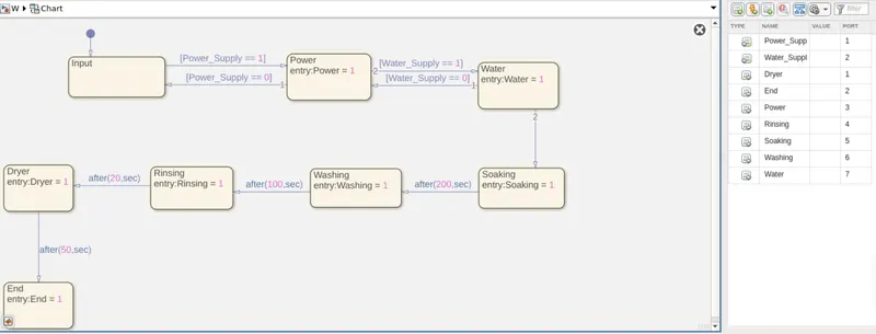
1. Switced OFF when non opertaional
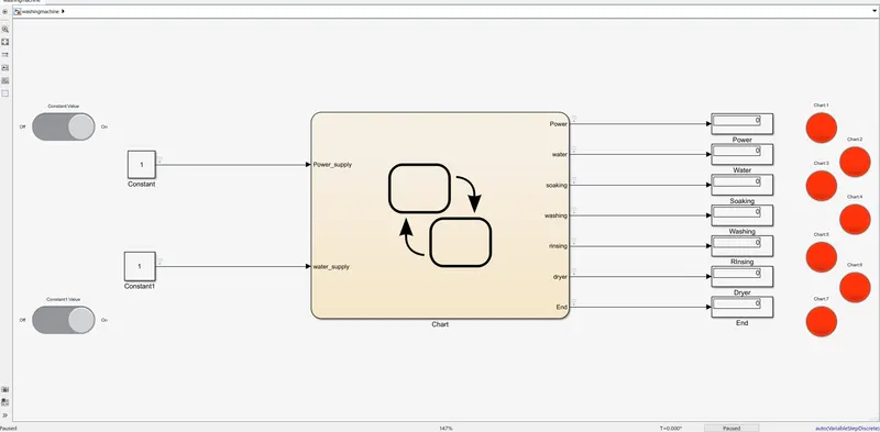
2. Power ON
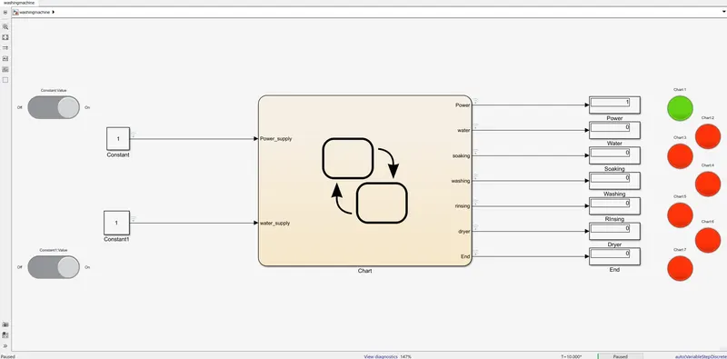
3. Water Supply ON
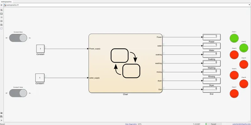
3. Soaking
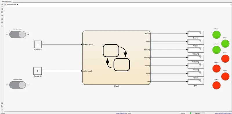
4. Washing ON
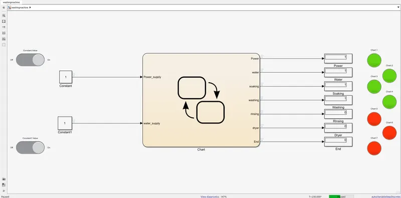
5. Rinsing
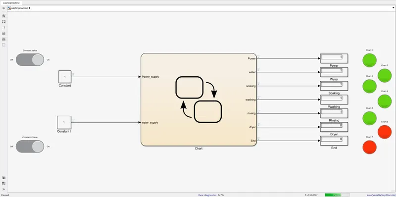
6. Drying
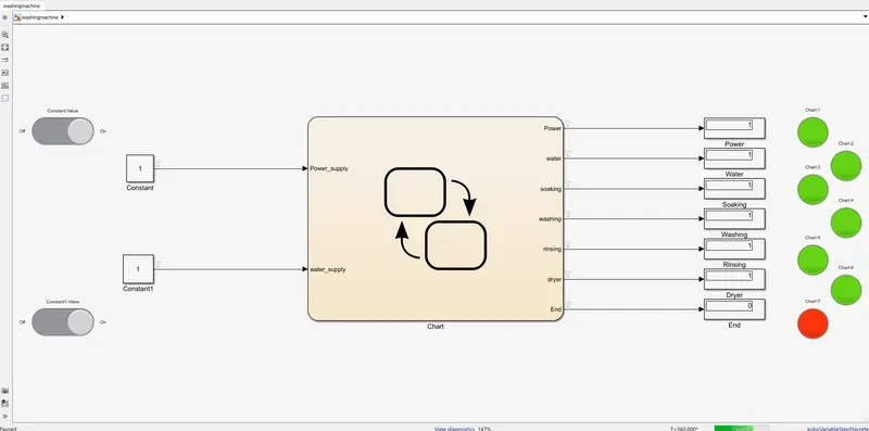
7. END process
This is what it looks like in the State flow chart:
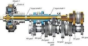
The Transmission operating mechanism:
To effect a gear change, selecting first gear, for example, the driver depresses the clutch, disengaging the input shaft. Using the shift lever, the driver selects the first gear, and the linkage moves the shift fork to connect the 1st-2nd locking collar with 1st gear, locking it to the output shaft. Now, when the clutch is released, engaging the input shaft, the output shaft turns because 1st gear is locked to the output shaft by the locking collar.
As the driver speeds up, selecting 2nd gear simply involved repeating the process, but moving the shift lever to 2nd gear. The shift shaft moves the shift fork to disengage 1st gear and engage 2nd gear. Releasing the clutch engages the input shaft again, this time routing power through 2nd gear. Changing to 3rd gear involves using a second shift linkage, shift fork, and locking collar, this one between 3rd and 4th gears.
Because the countershaft and output shaft turn at different speeds, moving from 1st to 2nd gear, trying to engage a higher gear while the vehicle is moving slower would be like trying to turn the shaft at two different speeds, which is impossible. Synchronizer rings are like tiny clutches, using friction to bring the locking collar and the gear to the same speed, at which point they easily mesh and power can be reapplied.
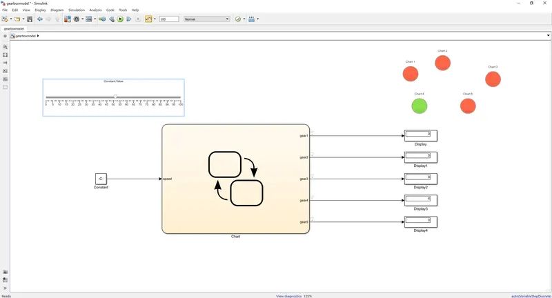
Before we go into the Simulink for the transmission box simulation w need to follow the below conditions for the setup.
Speed Range(km) Gear
0 to 15 1
16 to 25 2
26 to 40 3
41 to 60 4
Above 61 5
and by doing so we do that in a coded pttern in the state flow chart wich we get to see below:
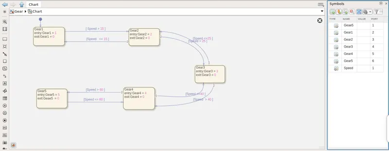
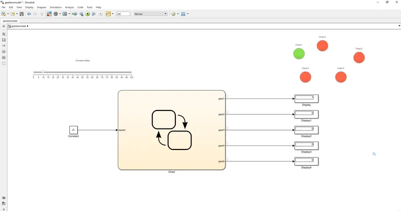
These are the following block setup did we need for the setup:
1. State flow chart
2. Slider
3.Constant
4. Display
5. lamps
and the output is just as similar as it is
0 to 15 1st gear
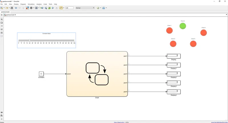
16 to 25 2nd gear
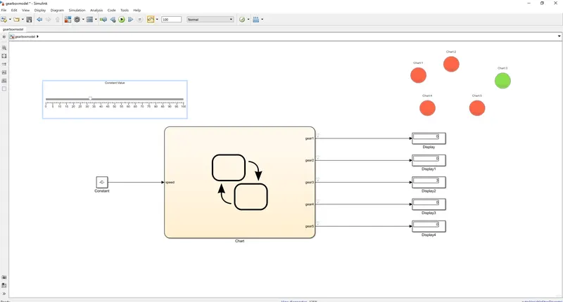
26 to 40 3rd gear
41 to 60 4th gear
Above 61 5th gear

and that's how we did the Gear shift logic in the simulink. As we can see the lamp is lit according to the gear it shows and the gear is at the current running according to the speed we selected from slider.