Project-1: Powertrain for aircraft in runways
PART A:
Question 1) Search and list out the total weight of various types of aircrafts.
Aircraft Gross Weight:
The aircraft gross weight ( also known as the all up weight and abbreviated AUW) is the total aircraft weight at any moimment during the flight or ground operation.
An aircraft's gross weight will decrease during a flight due to fuel and oil consumption. An aircrafts gross weight may also vary during a flight due to payload dropping.
At moment of releasing brakes, the gross weight of an aircraft is equal to its takeoff weight. During flight, an aircraft's gross weight is referred to as the en-route weight or in-flight weight.
Various Type Aircraft Weight:
MTOW = Maximum take-off weight, MLW = Maximum landing weight, TOR = Take-off run (SL, ISA+15°, MTOW), LR = Landing run (SL, ISA+15°, MLW)
| Type | MTOW [kg] | MLW [tonnes] | TOR [m] | LR [m] | ICAO category | FAA category |
|---|---|---|---|---|---|---|
| Antonov An-225 | 640,000 | 591.7 | 3500 | Heavy | Super | |
| Scaled Composites Model 351 Stratolaunch | 589,670 | 3660 | Heavy | Super | ||
| Airbus A380-800 | 575,000 | 394 | 3100 | 1930 | Heavy | Super |
| Boeing 747-8F | 447,700 | 346.091 | 3100 | 1800 | Heavy | Heavy |
| Boeing 747-8 | 443,613 | 306.175 | 3100 | Heavy | Heavy | |
| Boeing 747-400ER | 412,770 | 295.742 | 3090 | Heavy | Heavy | |
| Antonov An-124-100M | 405,060 | 330 | 2520 | 900 | Heavy | Heavy |
| Boeing 747-400 | 396,900 | 295.742 | 3018 | 2179 | Heavy | Heavy |
| Lockheed C-5 Galaxy | 381,000 | 288.417 | 2530 | 1494 | Heavy | Heavy |
| Boeing 747-200 | 377,840 | 285.700 | 3338 | 2109 | Heavy | Heavy |
| Boeing 747-300 | 377,840 | 260.320 | 3222 | 1905 | Heavy | Heavy |
| Airbus A340-500 | 371,950 | 240 | 3050 | 2010 | Heavy | Heavy |
| Airbus A340-600 | 367,400 | 256 | 3100 | 2100 | Heavy | Heavy |
| Boeing 777F | 347,800 | 260.816 | 2830 | Heavy | Heavy | |
| Boeing 777-300ER | 351,800 | 251.29 | 3100 | Heavy | Heavy | |
| Boeing 777-200LR | 347,450 | 223.168 | 3000 | Heavy | Heavy | |
| Boeing 747-100 | 340,200 | 265.300 | Heavy | Heavy | ||
| Airbus A350-1000 | 308,000 | 233.5 | Heavy | Heavy | ||
| Boeing 777-300 | 299,370 | 237.683 | 3380 | Heavy | Heavy | |
| Boeing 777-200ER | 297,550 | 213.00 | 3380 | 1550 | Heavy | Heavy |
| Airbus A340-300 | 276,700 | 190 | 3000 | 1926 | Heavy | Heavy |
| de Havilland Comet 1 | 50,000 | Medium | Large | |||
| Douglas DC-6A | 48,600 | Medium | Large | |||
| Douglas DC-6B | 48,500 | Medium | Large | |||
| Embraer 190[19] | 48,000 | 43 | 2056 | 1323 | Medium | Large |
| Caravelle III | 46,000 | Medium | Large | |||
| Fokker 100 | 46,000 | 39.95 | 1621 | 1350 | Medium | Large |
| Douglas DC-6 | 44,000 | Medium | Large | |||
| Avro RJ-85 | 42,000 | 36.74 | Medium | Large | ||
| Handley Page Hermes | 39,000 | Medium | Large | |||
| Embraer 175[20] | 37,500 | 32.8 | 2244 | 1304 | Medium | Large |
| Bombardier CRJ900[21] | 36,500 | 33.345 | 1778 | 1596 | Medium | Large |
| Embraer 170[22] | 36,000 | 32.8 | 1644 | 1274 | Medium | Large |
| Bombardier CRJ700 | 33,000 | 30.39 | 1564 | 1478 | Medium | Large |
| Douglas DC-4 | 33,000 | Medium | Large | |||
| Vickers Viscount 800 | 30,400 | Medium | Large | |||
| Bombardier Q400 | 28,000 | 28.01 | 1219 | 1295 | Medium | Large |
| Bombardier CRJ200 | 23,000 | 21.319 | 1918 | 1479 | Medium | Large |
| ATR 72-600 | 22,800 | 22.35 | 1333 | 914 | Medium | Large |
| Saab 2000 | 22,800 | 21.5 | 1300 | Medium | Large | |
| Embraer ERJ 145 | 22,000 | 19.3 | 2270 | 1380 | Medium | Large |
| ATR 42-500 | 18,600 | 18.3 | 1165 | 1126 | Medium | Small |
| Saab 340 | 13,150 | 12.930 | 1300 | 1030 | Medium | Small |
| Embraer 120 Brasilia | 11,500 | 11.25 | 1560 | 1380 | Medium | Small |
| BAe Jetstream 41 | 10,890 | 10.570 | 1493 | 826 | Medium | Small |
| Learjet 75[23] | 9,752 | 8.709 | 1353 | 811 | Medium | Small |
| Pilatus PC-24[24] | 8,300 | 7.665 | 893 | 724 | Medium | Small |
| Embraer Phenom 300[25] | 8,150 | 7.65 | 956 | 677 | Medium | Small |
| Beechcraft 1900D | 7,765 | 7.605 | 1036 | 853 | Medium | Small |
| Cessna Citation CJ4[26] | 7,761 | 7.103 | 1039 | 896 | Medium | Small |
| de Havilland Hercules | 7,000 | Medium | Small | |||
| Embraer Phenom 100 | 4,800 | 4.43 | 975 | 741 | Light | Small |
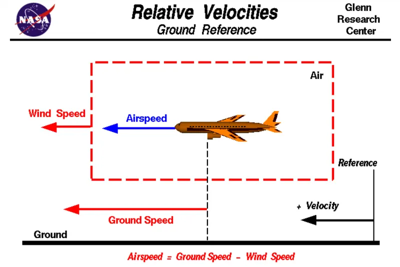
Question 2 ) Is there any difference between ground speed and air speed?
| Ground Speed | Air Speed |
| Ground speed is the airplane's speed relative to the surface of the earth | Airspeed is the speed relative to the air it is flying in. |
| Ground speed is what determines how fast an aircraft will get to its destination. | Airspeed is what determines whether there is enough airflow around an aircraft to make it fly. |
| Ground speed is simply the sum of airspeed and windspeed | It is independent of ground speed. |
Question 3) Why is it not recommended to use aircraft engine power to move it on the ground at Airport?
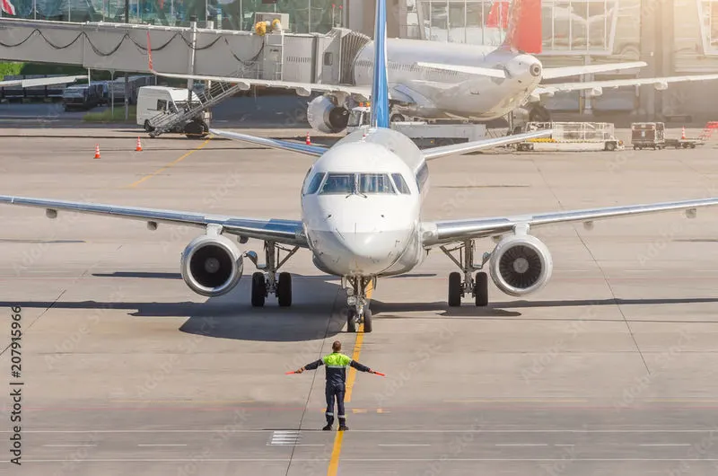
For movement on the ground the aircraft uses it own engine power, which is called taxing.
Although many aircrafts are capable of moving in backward using reverse thrust, as result the jet blast or prop wash might cause damage to the terminal building or equipment. Engine close to ground may also blow sand and debris forward and then suck them in to the engine, causing damage to the engine. Therefore there are push back trucks in the airport. A pushback truck lifts the front weel of the aircraft, their role in most airports is to move the aircraft away from the parking spot on to the taxiways, which is called towing.
Unwanted consequences mainly arising from the unintended movement of the aircraft during engine running.
- Effectively a loss of control can happen, especially during high power engine running. Damage can occur to the aircraft itself, other aircraft nearby or to airside structures.
- There is a risk of injury to ground support personnel who may be in relatively close proximity to the aircraft.
- It is easier for truck driver to see the surroundings better than the pilot sitting in the cockpit withl imited window. The pushback driver knows the airport better than the pilot.
- It also saves fuel, virgin Atlantic had proposed a new system in which push back truck will move the aircraft all the way to runway to save fuel and reduce impact of environment.
- The plane engines are very loud. When more than one plane will add up their sound, than it will not be pleasent for passangers and others near airport.
Question 4) How an aircraft is pushed to runway when its ready to take off?
An aircraft is pushed to runways by two methods:
i) Taxiing - is the movement of an aircraft on the ground, under its own power, in contrast to towing or pushback where the aircraft is moved by a tug. The aircraft usually moves on wheels, but the term also includes aircraft with skis or floats (for water-based travel).
An airplane uses taxiways to taxi from one place on an airport to another; for example, when moving from a hangar to the runway. The term "taxiing" is not used for the accelerating run along a runway prior to takeoff, or the decelerating run immediately after landing, which are called the takeoff roll and landing rollout, respectively.
The thrust to propel the aircraft forward comes from its propellers or jet engines. Reverse thrust for backing up can be generated by thrust reversers
Steering is achieved by turning a nose wheel or tail wheel/rudder; the pilot controls the direction travelled with their feet. Larger jet aircraft have a tiller wheel on the left side of the cockpit that acts as a steering wheel allowing the nosewheel to be turned hydraulically.
When taxiing, aircraft travel slowly. This ensures that they can be stopped quickly and do not risk wheel damage on larger aircraft if they accidentally turn off the paved surface. Taxi speeds are typically 16 to 19 kn (30 to 35 km/h;)
ii) Towing
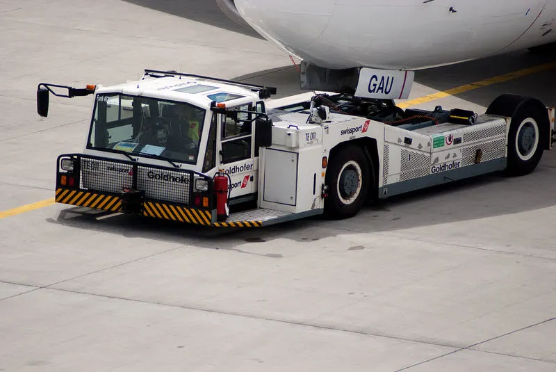
Movement of most aircraft around the airport and hangars is usually accomplished by towing with a towing vehicle or ‘tug’. The aircraft is attached it to the tow vehicle by the use of a towbar or other specialized methods that connect to or raise the nose or landing gear off the ground.
The forward movement of an aircraft, usually with engines off, using the power of a specialised ground vehicle attached to or supporting the nose landing gear. It may occur for the movement of both in service and out of service aircraft. This will affect the promulgation of procedures and the required qualification for those occupying the flight crew seats on the aircraft during the manoeuvre. As part of out of service repositioning of aircraft supervised by maintenance personnel, it may follow the Pushback from a nose-in gate of an empty aircraft with engines off.
Question 4) Learn about take off power, tyre design, rolling resistance, tyre pressure, brake forces when landing.
Take Off Power:
Takeoff is the phase of flight in which an aerospace vehicle leaves the ground and becomes airborne. For aircraft traveling vertically, this is known as liftoff.
Take off performance can be predicted using a simple measure of the acceleration of the aircraft along the runway based on force equilibrium.
The forces involved will be,
T – Thrust of propulsion system pushing aircraft along runway.
D – Aerodynamic Drag of vehicle resisting the aircraft motion.
F – Rolling resistance friction due to the contact of wheels or skids on the ground.
During take-off run the imbalance in these forces will produce an acceleration along the runway
dV/dt = (T - D - F)/m
where dV/dt is the acceleration along the runway and m is the mass of the vehicle.
Tyre Design:
An aircraft tire or tyre is designed to withstand extremely heavy loads for short durations. The number of tires required for aircraft increases with the weight of the aircraft, as the weight of the airplane needs to be distributed more evenly. Aircraft tire tread patterns are designed to facilitate stability in high crosswind conditions, to channel water away to prevent hydroplaning, and for braking effect.
Aircraft tires also include fusible plugs (which are assembled on the inside of the wheels), designed to melt at a certain temperature. Tires often overheat if maximum braking is applied during an aborted takeoff or an emergency landing. The fuses provide a safer failure mode that prevents tire explosions by deflating in a controlled manner, thus minimizing damage to aircraft and objects in the surrounding environment.
Carcass plies are used to form the tire. They are sometimes called casing plies. An aircraft tyre is constructed for the purpose it serves.
- They support the weight of an aircraft while it is on the ground.
- It also provides the necessary traction for braking and stopping of an aeroplane.
- Tyre also helps to absorb the shock of landing and provide cushioning the roughness of takeoff, roll-out, and taxi operations.
Unlike an automobile or truck tyre, it does not have to carry a load for a long period of continuous operation. However, an aircraft tyre absorbs the high impact loads of landing, and also it’s operating at high speeds for a short time when required.
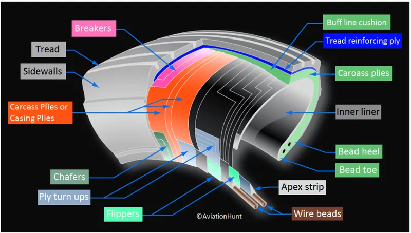
Technical aspects of the tyre:
Retreading – Retreading is methods of restoring a worn tyre by renewing the tread area or by renewing the tread area plus one or both sidewalls. Repairs are included in the tyre retreading process.
Load Rating – Load rating is the maximum permissible load at a specified inflation pressure.
Ply Rating – Ply Rating is used to identify the maximum recommended load rating and inflation pressure for a specified tyre. It is an index of tyre strength.
Speed Rating – The speed rating is the maximum takeoff speed to which the tyre has been tested.
Skid Depth – Skid depth is the distance between the tread surface and the deepest groove as measured in the mould.
Rolling Resistance:
Rolling resistance, sometimes called rolling friction or rolling drag, is the force resisting the motion when a body (such as a ball, tire, or wheel) rolls on a surface. It is mainly caused by non-elastic effects; that is, not all the energy needed for deformation (or movement) of the wheel, roadbed, etc., is recovered when the pressure is removed. Two forms of this are hysteresis losses (see below), and permanent (plastic) deformation of the object or the surface (e.g. soil).
The "rolling resistance coefficient" is defined by the following equation:

- where
 is the rolling resistance force
 is the dimensionless rolling resistance coefficient or coefficient of rolling friction (CRF), and
 is the normal force, the force perpendicular to the surface on which the wheel is rolling.
Tyre Pressure:
Airplane wheel/tire assemblies are inflated to high pressures, often in excess of 200 pounds per square inch (psi). Because the pressure in a nitrogen bottle or tire-servicing cart can be as high as 3,000 psi, connecting the nitrogen source directly to the wheel without a regulator subjects the wheel to sudden high pressure that can exceed the design limits for the wheel, the wheel tie bolts, or the tire.
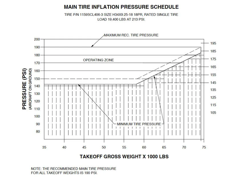
Aircraft tyre pressure chart
Brake forces when landing:
The brake units are powered by the hydraulics system. An electrical signal is sent from the flight deck to hydraulic actuators near the main landing gear. Here, hydraulic fluid at 3,000 pound per square inch is used to force the brake unit against the wheel, thus slowing it down.
the hydraulic system and all its associated architecture and instead used electricity to power the brakes. When the pilots press on the brake pedals, an electrical signal is sent to the brake unit on the wheel. Here, electrically powered actuators are used to press the carbon brake disc against the wheel, slowing it down.
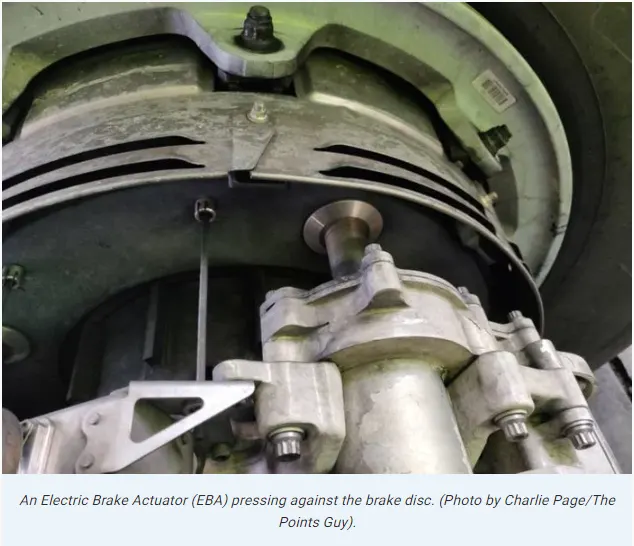
These then send signals to the four Electronic Brake Actuator Controllers (EBAC) which control the rate of braking on the wheels. Each wheel has four Electric Brake Actuators (EBA), a kind of piston which presses against the carbon brake discs.
The brake disks themselves are made up of two parts. Firstly, there are the rotors. These are connected to the wheel by drive tabs (in the video below they are the black rectangles on the rotor disks). As these drive tabs are in contact with the inside of the wheel, they spin at the same speed. Depending on the brake manufacturer, there are either four or five of these rotors on each brake assembly.
The second part of the disks are the stators. These sit around each rotor and are fixed in place and thus don’t move. As the wheel turns, the rotors spin round inside the stators.
When the brakes are applied, the four EBAs apply pressure to the first stator. This in turn squeezes the stationary stators up against the spinning rotors and it’s this friction which slows the wheel down.
PART B:
Question 6. A.) With necessary assumptions, calculate the force and power required to push / pull an aircraft by a towing vehicle.
The different forces and power required to push / pull an aircraft by a towing vehicle is been doscussed on 5th question
Now, the given data is taken from the towing truck TMX-150-9 & Aircraft Airbus A319
Given Data:
- Mass of the truck= 8300 Kg
- Mass of aircaft = 75500 Kg
- Length of Aircraft = 33.84m
- Velocity of Truck = 25Kmph
- Height of the aircraft = 11.76m
- Air density = 1.225 Kg/m^3
- Drag coefficient (Cd) = 0.75
- Rolling resistance coefficient (μrr) = 0.013
- Gravitational constant(g) = 9.8 Nm
Calculation for Rolling Resistance (Frr)
Frr = μrr * m* g
m = Mass of the truck + Mass of aircraft = 8300 + 75500
m = 83800 Kg
Substituting values in the formula
Frr = 0.013 * 83800 *9.8
Frr = 10676.12 Nm
Calculation of aerodynamic drag(Fad)
Fad = 0.5 * ρ * cd *A * V^2
Velocity of truck (m/sec) = 25/3.6 = 6.95 m/sec
Area = Length of the aircraft * Height of aircraft = 33.84 * 11.76
Area = 392.544 m^2
Fad = 0.5*1.225*0.75*392.544*6.95^2
Fad = 8816N
Total Force required to push/Pull an aircraft by a towing vehicle is
F_total = Frr + Fad = 10676.12 + 8816
F_total = 19492.12N
Power = F_total * Velocity = 19492.12* 6.95
Power = 135.470 kW
Question 6B) Develop the model for the calculated force and power using Simulink.
The simulink model of above calculated force is:
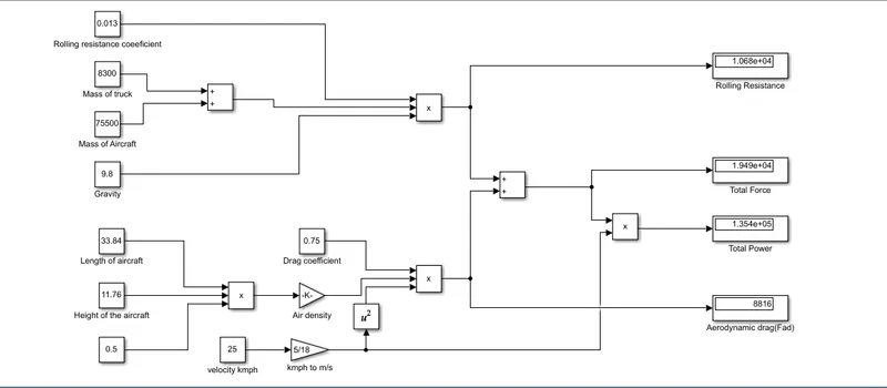
- The Frr and Fad is calculated using the formula stated in above question using add , product , gain and square blocks and displayed in the display block
- total force is result summation of Frr and Fad values which is obtained using add block and displayed in the display block
- Total power is obtained by the product of force and velocity and displayed in the display block.
Question 7. A). Design an electric powertrain with type of motor, it’s power rating, and energy requirement to fulfill aircraft towing application in Simulink. Estimate the duty cycle range to control the aircraft speed from zero to highest. Make all required assumptions. Prepare a table of assumed parameters. Draw a block diagram of powertrain.
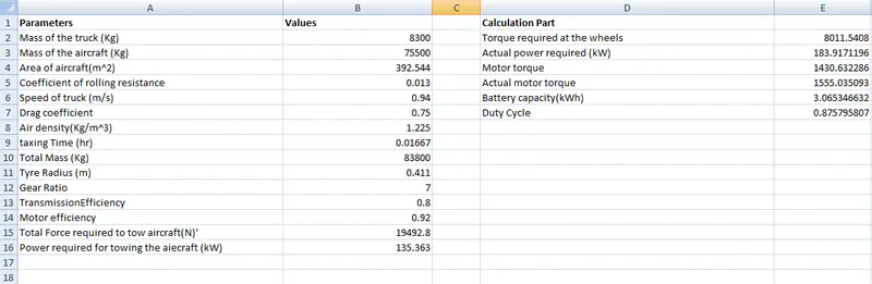
- In the 6th question we found the power required for towing a aircraft
- 315/70 R15 is the tyre specification for towing truck TMX-150-9
Data for Designing:
- Force required to tow the aircraft = 19492.8N
- Power required for towing Aircraft = 135.363 Kw
- Tyre radius of towing truck = 0.411m
- Gear Ratio = 7
- Transmission Efficiency(ηt) = 80%
- Motor Efficiency(ηm) = 92%
Calculation
Torque required at the wheels(Tw)
Tw = Total force * Tyre Radius = 19492*0.411
Tw = 8011.212Nm
Actual power required(Pac)
Pac = ( power required)/(ηt*ηm) = 135.363/(0.8*0.92)
Pac = 183.917 Kw
To Calculate motor Torque(Tmac)
Tm = (Tw)/(Gear ratio* ηt) = 8011.212/(0.8*7)
Tm = 1.430 kNm
Actual Motor Torque (Tmac)
Tmac = Tm/ηm = 5.6/0.92
Tmac = 1.555kNm
To calculate battery capacity
The Towing truck takes 15 minutes for taxing
15 min = 0.016667 hours
Battery Capacity = Pac*hours = 0.016667*183.917
Battery Capacity = 3.067kWh
The battery can deliver the power output of 3.067kWh if i use 210 kW battery i can run the towing truck easily
Duty Cycle Calculation
Duty cycle = power req (Pac)/power rated (battery capacity) = 183.917/210
Duty cycle = 0.875
To run the towing tractor for 15 min with speed of 7 m/s the duty cycle is varies between (0 - 0.875)
At 0.875 the towing tractor reaches its maximum speed of 7m/sec.
Drivetrain Model
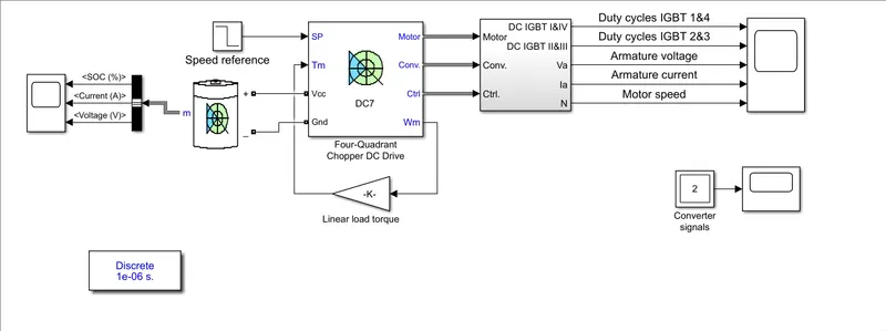
Inputs:
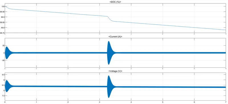
From the above plot we can understand the battery SOC , Voltage and current
- at the starting time we can see the sudden rush of starting current
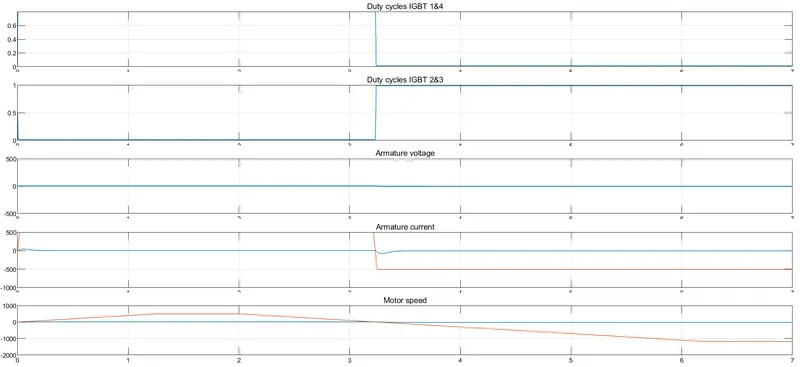
- From the above plot we can see the duty cycle of the power converter
- The duty cycle is sett as 87% for the battery usageof the battery power
- By using the DC7 converter the motor is tested in both forward and reverse direction.
Question B. Also, Design the parameters in excel sheet.