Project-1: Powertrain for aircraft in runways
** This assignment is for the 13th batch live session**
AIM:
Part A:
1. Search and list out the total weight of various types of aircraft.
2. Is there any difference between ground speed and airspeed?
3. Why is it not recommended to use aircraft engine power to move it on the ground at the Airport?
4. How an aircraft is pushed to the runway when it's ready to take off?
5. Learn about take-off power, tire design, rolling resistance, tyre pressure, and brake forces when landing.
ANSWERS:
1. list out the total weight of various types of aircraft.
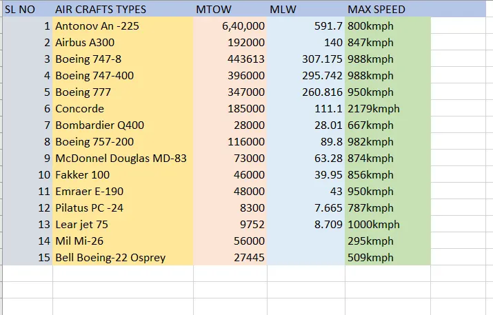
MTOW = Maximum take-off weight,
MLW = Maximum landing weight,
MAX Speed = Maximum Speed.
Maximum Landing Weight:
The maximum landing weight (MLW) is the maximum aircraft gross weight due to design or operational limitations at which an aircraft is permitted to land.
The operation landing weight may be limited to a weight lower than the maximum landing weight by the most restrictive of the following requirements. Aircraft also have a maximum take-off weight (MTOW) which is almost always higher than the maximum landing weight, so that an aircraft can weigh less upon landing due to burning fuel during the flight
> Aircraft performance requirements for a given altitude and temperature
> landing field length requirements,
> approach and landing climb requirements.
> Noise requirements
Maximum Take-Off Weight
The maximum take-off weight (MTOW) or maximum gross take-off weight (MGTOW) or maximum take-off mass (MTOM) of an aircraft is the maximum weight at which the pilot is allowed to attempt to take off, due to structural or other limits. It is the heaviest weight that should be limited to ensure the aircraft can fly safely during take-off. The analogous term for rockets is gross lift-off mass or GLOW. MTOW is usually specified in units of kilograms, or pounds. regulated take-off weight", varies according to flap setting, altitude, air temperature, length of the runway, and other factors. It is different from one take-off to the next, but can never be higher than the MTOW.
Here MTOW is the heaviest weight at which the aircraft has been shown to meet all the airworthiness requirements applicable to it. MTOW of an aircraft is fixed and does not vary with altitude, air temperature, or the length of the runway to be used for take-off or landing. At its MTOW an aircraft complies with all the structural and performance requirements. This MTOW of the aircraft is fixed.
2. Difference between ground speed and airspeed:
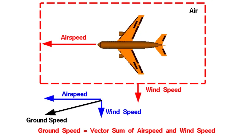
Ground speed:
Ground speed is the sum of airspeed and wind speed.
If the aircraft is flying in the same direction as the wind is blowing, the aircraft experiences tailwind, and its ground speed is higher than its airspeed.
It is the horizontal speed of an aircraft relative to the ground.
It is vital for accurate navigation that the pilot has an estimate of the ground speed that will be achieved during each leg of a flight an aircraft heading vertically would have a ground speed of zero. For a reference point picked on the ground, the aircraft moves relative to the reference point at the ground speed to the wind speed must be done according to rules for vector comparison.
It is measured using GPS and indicated airspeed is measured using sensors on the plane called pitot tubes.
Ground speed can be determined by the vector sum of the aircraft's true airspeed and the current wind speed and direction.
Airspeed:
Airspeed = Ground speed Wind speed
airspeed is the speed at which an aircraft is moving relative to the air it is flying in.
it's also the speed at which the air is flowing around the aircraft's wings.
Its speed is relative to air.
the common conventions for qualifying airspeed are indicted airspeed (1AS), calibrated airspeed (CAS), equivalent airspeed (EAS), true airspeed (TAS), and density airspeed.
Airspeed cannot be directly measured from a ground position but must be computed from the ground speed and the wind speed.
Airspeed is the vector difference between the ground speed and the wind speed.
3. Why is it not recommended to use aircraft engine power to move it on the ground at the Airport?
> The engine creates a space where any equipment can suck or pull into the engine if anything is too close to it when it is running.
> Flammable materials or oils or gases near get absorbed and get blasted because of rupture speed which can get heat around it.
> The noise obtained from the plane is higher which may affect humans and also the animals' ears and bodies due to the high decibels of sound. And also fumes gave more heat.
> People and things can damage if they are near the plane. Because air intake is very powerful it forms like a little cyclone which can suck human bodies easily.
> The engine outlook or body may get damaged due to ground force or by any other causes.
> Due to this high suction force, the small particles near the engine like dust particles, stones, papers, plastic, etc pull into the engine which may damage the engine or its parts.
Also, this will cause a lot of pollution and carbon emission and noise pollution, etc.
4. How an aircraft is pushed to the runway when it's ready to take off?
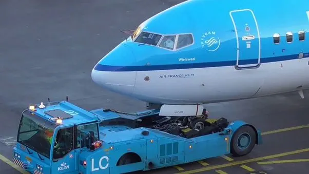
The aircraft is pushed onto a runway with the help of a towing vehicle also known as a tow tractor when it is ready for take-off.
Taxi-Ing the aircraft involves moving it along the ground from where it has been parked, up to the start of the runway. During taxi-Ing, there are other checks which need to be done, mainly to ensure that the steering on the groundworks as it should do.
When the pilot calls 'ready for departure', there are several possible answers he could get from Air Traffic Control. He may be asked to hold his position, especially if other aircraft are waiting to take off. He may be asked to line up and wait', which means he can start on the runway, and position the aircraft ready to move down the runway or the take-off roll.
The take-off roll or ground roll is the portion of the take-off procedure during which the airplane is accelerated from a standstill to an airspeed that provides sufficient lift for it to become airborne.
But if anything seems wrong during the take-off roll, the pilot will abort the take-off, which means he will apply the brakes and come to a halt on the ground before the end of the runway. Aborted take-offs happen to all aircraft, Large and small though quite rarely.
Pushback is an airport procedure during which an aircraft is pushed backward away from an airport gate by an external power. Pushbacks are carried out by special, low-profile vehicles called pushback tractors or tugs.
Although many aircraft are capable of moving themselves backward on the ground using reverse thrust, the result might cause damage to the terminal building or equipment. Engines close to the ground may also blow sand and debris forward and then suck them into the engine, causing damage to the engine. A pushback is therefore the preferred method to move the aircraft away from the gate.
Once the pushback is completed, the towbar is disconnected, and any bypass pin is removed. The ground handler will show the bypass pin to the pilots to make it clear that it has been removed. The pushback is then complete, and the aircraft can taxi forward under its power. the take-off is an important part of flying. It is usually not difficult, but many things can go wrong. So, the take-off should be treated with care and caution to ensure a safe flight.
5. Learn about take-off power, tire design, rolling resistance, tyre pressure, and brake forces when landing.
Take-off is the phase of flight in which an aerospace vehicle leaves the ground and becomes airborne. The take-off and initial climb are two of the most critical safety phases of the aircraft flight. The combined analysis of both phases is referred to as the aircraft take-off performance. Take-off performance can be predicted using a simple measure of the acceleration of the aircraft along the runway based on force equilibrium.
The forces involved will be,
T- Thrust of propulsion system pushing aircraft along the runway
D-Aerodynamic Drag of vehicle resisting the aircraft motion.
F Rolling resistance friction due to the contact of wheels or skids on the ground.
During the take-off run, the imbalance in these forces will produce an acceleration along the runway.
dv/dt = (T-D-F)/m
Where 'dv/dt' is the acceleration along the runway and 'm' is the mass of the vehicle.
The take-off distance consists of two parts, the ground run, and the distance from where the vehicle leaves the ground until it reaches 50 ft (or 15 m). The sum of these two distances is considered the take-off distance.
Tyre design:
Two types of tires are used in an aircraft application:
bias-ply tires and radial tires.
The basic difference between a radial tyre and a bias (cross-ply) tyre is the lay of the plies within the tyre carcass. The remainder of the tyre is very similar in construction in both.
Radial tyres have a feature of a rigid belt and flexible carcass which provides a greater number of landings and less rolling resistance. It has fiber stands of the ply fabric oriented at 90° to the direction of radiation and the tyre sidewall. This restricts flexibility bidirectional flexibility of the sidewall while it strengthens the tyre to carry heavy loads. Due to their unique construction, radial tyres are resistant to penetration ad cuts.
Due to stiffer thread, they distribute weight evenly. Thus, providing greater traction. Radial tyres have an advantage in terms of reducing the heat better. It can only a small portion of the radial tyre will be affected in case of any damage of this type. these tyres have the word RADIAL On the sidewall.
Bias/Cross-ply Tyre
It has the fabric bias oriented with and across the direction of rotation and the sidewall.
Since fabric can stretch on the bias, the tyre is flexible and absorb loads. Tyre strength is obtained by adding piles. It is cut-resistant in the sidewall area. These tyres do not offer as much smoothness in terms of riding quality. More than in aircraft this is used in heavy-duty carriage trucks and buses. One of the best advantages of this type of method is that if there is any cut in the tread area, it can affect only a small portion of the tyre.
Rolling Resistance:
The force that resists the motion of a body rolling on a surface is called the rolling resistance or the rolling friction.
The rolling resistance can be expressed as
Fr = c W/r
Where
Fr = rolling resistance or rolling friction (N)
C = rolling resistance coefficient
W = m * ag
m = mass of body (kg, Ib)
ag acceleration of gravity (9.81 m/s2) radius of wheel (mm, in)
Rolling resistance sometimes called rolling friction or rolling drag is the force resisting the motion when a body (such as a ball, tire, or wheel) rolls on a surface.
It can be seen in the aircraft taking off from the runway and while landing on the runway with the help of other wheels.
The friction between the aircraft and the runway will be proportional to the normal force exerted by the aircraft on the runway.
F = µ(W-L)
The normal force will be the difference between the Weight(W) of the aircraft and lift (L), and the friction coefficient (u) will be typically of a magnitude of 0.02 for a standard tarmac runway. it is the force resisting the motion when a body rolls on the surface. It can be observed in the aircraft when it take-off off from the runway and while landing on the runway with its wheels.
Tyre pressure
Aircraft tyres operate at such high extremes of pressure, load, and speed, that their care and service are critically important for the short durations. It's generally operated at high pressures, up to 200 psi (14 bar; 1,400 KPa) for airliners, and even higher for business jets. The main landing gear on the Concorde was typically inflated to 232 psi (16.0 bar), whilst its tail bumper gear tires were as high as 294 pas (20.3 bar). So, the most important action an operator can take to prevent tire-related events is to maintain proper tire inflation pressure. The no of tyre required for aircraft increases with the weight of the aircraft, as the weight of the airplane needs to be distributed more evenly. If we fail to keep aircraft tires properly, inflated can lead to very serious consequences. One relatively easy way to help avoid those consequences is to check tire pressures regularly and service them as necessary. Tyres and tubes should be stored in a cool, dry place out of direct sunlight.
Brake force when landing:
Aircraft brakes stop a moving aircraft by converting its kinetic energy to heat energy using friction between rotating and stationary discs located in brake assemblies in wheels. As of now, All modern commercial aircraft have automatic brake systems. Just like a car, these systems also have an anti-lock braking system (ABS) that prevents the tires from sliding down a wet runway. Stopping a 200-tonne aircraft landing at 180 mph requires a lot of braking force. Bringing an aircraft down to the runway from 37,000 feet is one part of the challenge. It's over until the aircraft is safely parked at its gate.
To calculate the brake force required to stop the aircraft, we have to first estimate the kinetic energy carried by it mainly used for the electrical breaking as well and this can be determined by
E = ½ mv^2
Aircraft breaks are two types
> Steel brakes were used for years as a standard in the aviation sector. They are relatively heavy and can only withstand temperatures up to 2,000°C (3,600°F). They must be replaced after an average of 1,000 landings.
> Carbon brakes have become the standard on newer aircraft in the meantime. They are considerably lighter than steel brakes. Now the steel is replaced with carbon breaks. they are much sturdier, having the ability to withstand temperatures of up to 3,000°C (5,400°F). Even the service life is longer. Carbon brakes can handle 2,000 landings on average. But carbon brakes are more expensive than steel brakes.
Part B:
6. A. With necessary assumptions, calculate the force and power required to push / pull an aircraft by a towing vehicle.
B. Develop the model for the calculated force and power using Simulink.
7. A. Design an electric powertrain with type of motor, it’s power rating, and energy requirement to fulfill aircraft towing application in Simulink. Estimate the duty cycle range to control the aircraft speed from zero to highest. Make all required assumptions. Prepare a table of assumed parameters. Draw a block diagram of powertrain.
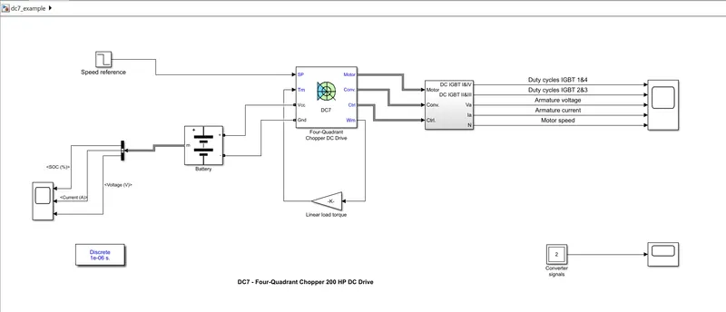
(Hint :DC7 Block)
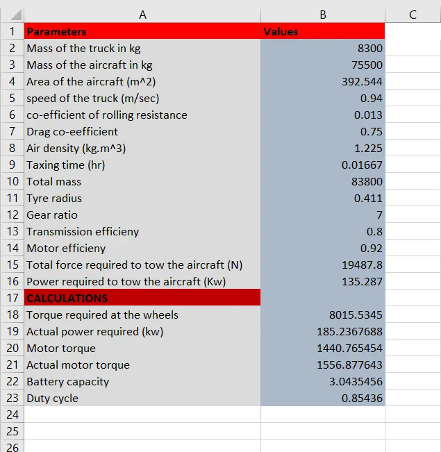
B. Also, Design the parameters in excel sheet.
ANSWERS:
6. A. With necessary assumptions, calculate the force and power required to push/pull an aircraft by a towing vehicle.
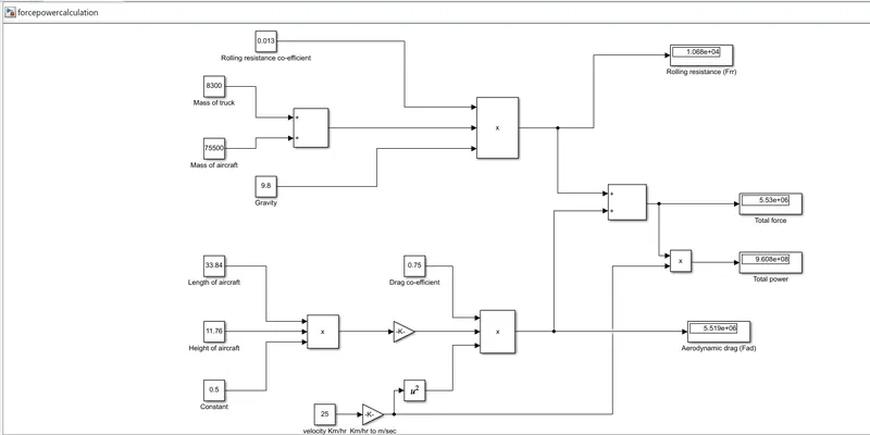
B. Develop the model for the calculated force and power using Simulink.
Let the force acting on the aircraft are rolling resistance force and aerodynamic force which can be calculated as follows;
Rolling resistance force:
Frr = µrr * m * g
Where;
µrr = co-efficient of rolling resistance = 0.002
m = mass of the craft
g = gravitational force
Lets take the gross weight of the aircraft = 50,000kg
Therefore;
Frr = 0.002 * 50000*10
Frr = 1000 N
- Aerodynamic force
Fad = ½*Cd*ρ*A*V2
Where;
Cd = drag co-efficient = 0.025
ρ = air density = 1.125
Area(A) = 150 m^2
Velocity = 4m/s
Therefore;
Fad = ½*0.025*1.125*150*4^2
Fad = 33.75 N
As the vehicle is moving with a low speed, the aerodynamic force is neglected hence the total force acting on it will be 1000N
The forces required to push/pull an aircraft by a towing vehicle are rolling resistance and aerodynamic drag force.
Let us consider a towing truck TMX-150-9 and an Aircraft airbus A319
Specification:
Mass of the truck = 8300 Kg
Mass of the aircraft = 75,000 Kg
Length of the aircraft = 33.84m
The velocity of the truck = 25 Kmph
Height of the aircraft = 11.76 m
Air density = 1.125 kg/m^3
Drag co-efficient Cd = 0.75
Rolling resistance co-efficient µrr = 0.013
Gravitational constant g = 9.8 Nm
- Calculation of rolling resistance Frr
Frr = µ*m*g
m = mass of the truck + mass of the aircraft = 8300+75500
m = 83800 kg
Frr = 0.013*83800*9.8
Frr = 10676.12 Nm
ii) Calculation of Aerodynamic drag
Fad = ½*Cd*ρ*A*V2
Velocity of the truck in m/sec = 25/3.6 = 6.95 m/sec
Area = length of the aircraft*Height of the aircraft = 33.84*11.76
Area = 392.544 m^2
Fad = 0.5 * 1.125 * 0.75 * 392.544 * 6.95^2
Fad = 8816 N
The total force required to push /pull an aircraft by a towing vehicle is
Ftotal = Frr + Fad
Ftotal = 10676.12 + 8816
Ftotal = 19492.8 N
The total power required to push /pull an aircraft by a towing vehicle is
Power = Ftotal * velocity = 18258.8 * 6.95
Power = 135.363 Kw
b)
Model link:
7.
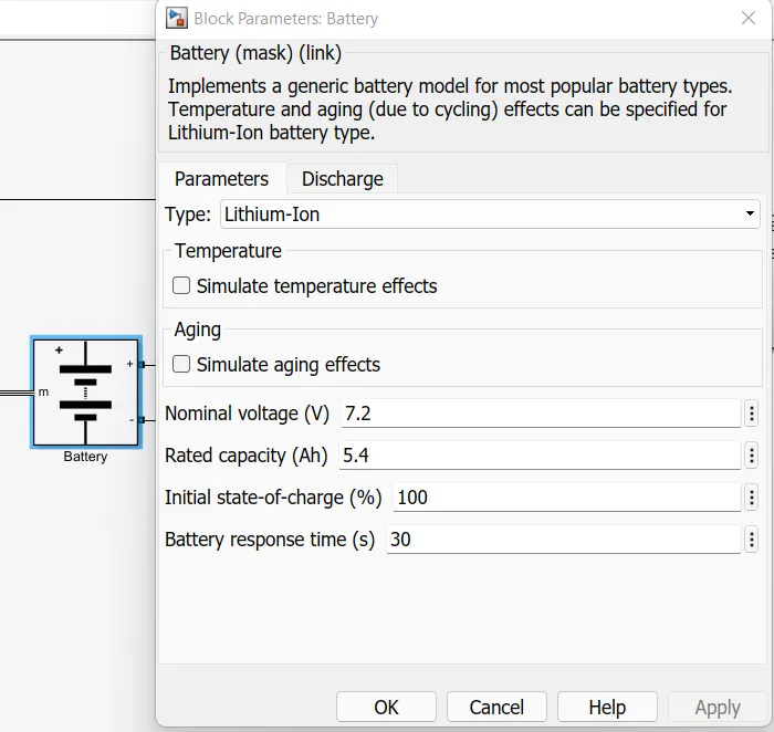
Generic battery block in older version 2018a
CALCULATION:
Specification of towing truck:
Tyre specification: 315/70R15
Towing truck model: TMX-150-9
Designing data:
Force required to tow the air craft: 19492.8 N
Power required for towing the aircraft = 135.363 KW
Tyre radius for the towing truck = 0.411 m
Gear ratio = 7
Transmission efficiency =80 %
Motor efficieny = 92%
Calculation:
Torque required at the wheels (Tw)
Tw = total force * tyre radius = 19492*0.411
Tw = 8011.212 Nm
Actual power required Pac
Pac = (Power required)/(Transmission efficiency * Motor efficieny)
Pac = 135.363/(0.8*0.92)
Pac = 183.917 KW
Therefore, the motoring power rate should be 190KW
To calculate motor torque Tm
Tm = (Tw)/(Gear ratio*transmission efficiency)
Tm = 8011.212/(0.8*7)
Tm = 1.430 KNm
Actual motor torque (Tmac)
Tmac = TM/(motor efficiency) = 5.6/0.92
Tmac = 1.555 KNm
To calculate battery capacity
The towing tractor takes 15 minutes for taxing therefore 15min = 0.016667 hours
Battery capacity = Pac * hours = 0.01667 *183.917
Battery capacity = 3.067 KWh
Duty cycle calculation:
Duty cycle = (power required (Pac))/battery capacity = 183.917/210
Therefore Duty cycle = 0.875
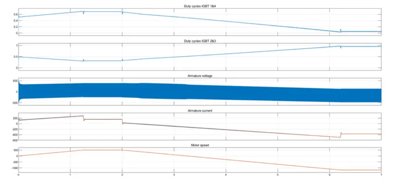
Output:
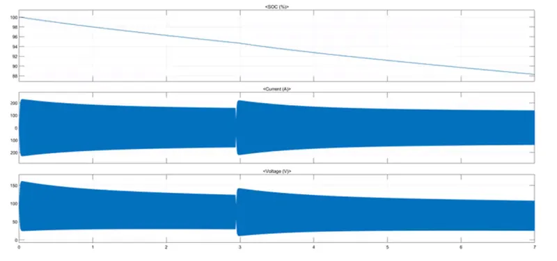
INPUTS:
CALCULATION IN EXCEL:
FILE LINK: