Project-1: Powertrain for aircraft in runways
Aim- study about Towing of aircraft at airport and make models of the Towing application used in the aviation industries.
objectives-
Part A:
1. Search and list out the total weight of various types of aircrafts.
2. Is there any difference between ground speed and air speed?
3. Why is it not recommended to use aircraft engine power to move it on the ground at Airport?
4. How an aircraft is pushed to runway when its ready to take off?
5. Learn about take off power, tyre design, rolling resistance, tyre pressure, brake forces when landing.
Part B:
6. A. With necessary assumptions, calculate the force and power required to push / pull an aircraft by a towing vehicle.
B. Develop the model for the calculated force and power using Simulink.
7. A. Design an electric powertrain with type of motor, it’s power rating, and energy requirement to fulfill aircraft towing application in Simulink. Estimate the duty cycle range to control the aircraft speed from zero to highest. Make all required assumptions. Prepare a table of assumed parameters. Draw a block diagram of powertrain.
B. Also, Design the parameters in excel sheet.
Part -A
[1]
There are different aircrafts with different weight carring capacity. some of are listed below.
| Aircraft name | length(feet) | Cerb Weight(lbs) | Total Weight(lbs) |
| Cessa 172 | 27 | 1450 | 2450 |
| Citation Jet M2 | 42 | 6990 | 10700 |
| Boeing 762-300 | 185 | 195000 | 400000 |
| Boeing 787-800 | 186 | 264500 | 502500 |
| Boeing 777-300 | 242 | 354000 | 660000 |
| Boeing 747-400 | 232 | 407000 | 910000 |
| Airbus A320 | 123 | 82000 | 170000 |
| Airbus A330 | 210 | 274000 | 507000 |
| Airbus A380 | 240 | 610700 | 1234600 |
[2]
The relative speed between aircraft and the ground is called Ground speed. whereas relative speed between aircraft and the wind is called Air speed of the aircraft. Airspeed is nothing but the speed of air respective to the wing of the aircraft. there are no difference in the Airspeed and Ground speed when surronding air is stationary or not moving.
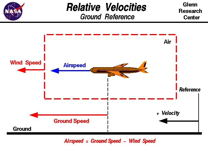
As shown in above figure there is a REFERENCE point at the ground so we are measuring all the speed with respect to the ground, so as shown the wind speed is in the direction of the aircraft(It can be any direction). The Vector Difference Between Ground speed and wind speed can be called as Air speed i.e.
Air speed = Ground speed - Wind speed
When we talk about lift force, It is refered to the Air speed and when we talk about the velocity of the aircraft and distance and time between stops, we're refering to the Ground speed.
[3]
When we talk about the mobility of the aircraft at airport from one point to another we use Towing vehicle. we can also use the Engine of the aircraft alone to propel the aircraft but most of the Aircraft uses Jet Engine which uses fuel to heat up the air and make a thrustive force by forcing this air to the narrow opening of the Jet engine (Newtons third law of motion), so this Jet wind is very powerful Itself to damage the Equipment or surronding of the Aircraft, therefore we do not use the Jet engines of the plane to move the aircraft at the airport.
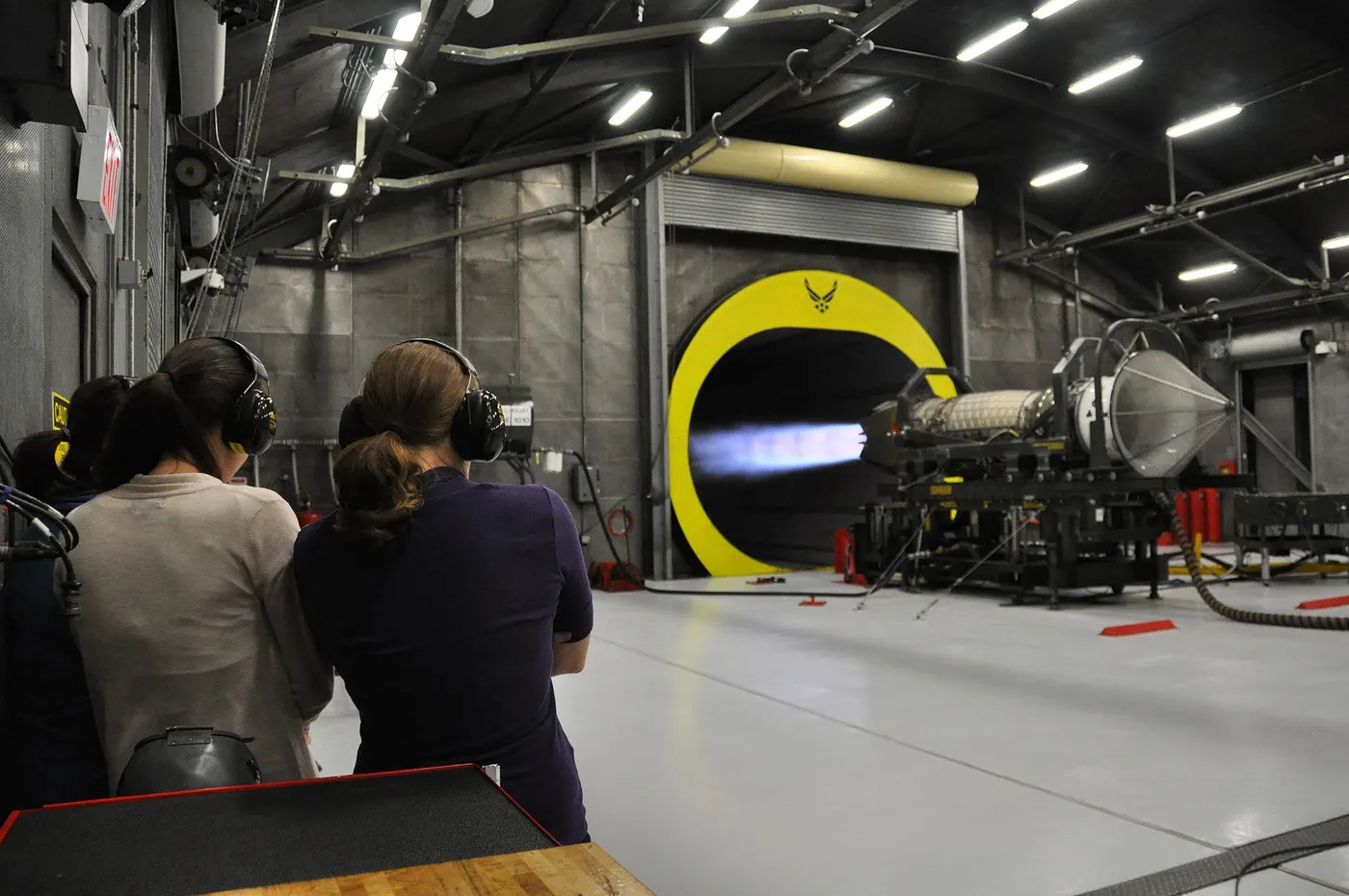
Turbines are also used in the engine to provide initial momentum to the air and It sucks air ahead of engine so it is very crucial that nothing should be come ahead of Jet engine when It is operated otherwise It will be sucked and cut into pieces or could damage engine Itself.
The working personnals safety is most concern so for safety purpose and to avoid accidents at the airport we minimize the aircraft engine use at the ground.
[4]
The aircraft after Refueling and boarding of the passenger and baggage, The aircraft is ready to depart but it is in the parking place so to move the Aircraft from parking to the runway a Towing vehicle pushed it to the runway by a towbar atteched oto the nose wheel or in mordern version, by actually lifting the aircraft. that is more reliable and reqiure less time to couple or decouple the vehicle.
After The towing vehicle move to the Aircraft to the runway at the position to take off, It will be decoupled and send back to ready the aircraft to takeoff. then after recieving permission from air traffic controller the piolet starts the aircraft engine and aircraft moves my propulsion of the aircraft engine.
[5]
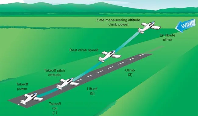
Take off power- Takeoff power is the power required by the aircraft engine to overcome the rolling resistance and airdrag forces and safely leave the earth surface with certain climb rate so that aircraft will successfully takeoff from the runway. Take off power may or maynot be the maximum engine power and it is usually large in value.
for takeoff we need to move aircraft from zero speed to takeoff speed and more untill aircraft will be reach certain altitude, so acceleration
`(dV)/(dt)=(T-D-F)/m`
where,
V = Velocity
T = Thrust by engine
D = Air drag force
F = Rolling resistance force
m = mass of the aircraft
so the Power Required by the Aircraft engine is,
Power(shaft) = `(T*V)/eta`
where,
`eta =` 50-80% depending upon the tyre of propeller system used.
Tyre Design- The aircraft tyre is not an ordinary tyres like heavy vehicle used, there are following consideration when we decide to make an aircraft Tyre,
1. They support the weight of an aircraft while it is on the ground.
2. They provide traction for braking under landing conditions.
3. They absorb shock of landing and cushioning the roughness of takeoff, rollout and taxi operations.
4. They should withstand Heavy load at high inflation for short durations.
To meet this conditions, Tyre should have to design and make accordingly.
There are high quality tread and a good number of ply material between the tread and deepest groove, with a sidewall reinforced with bead to withstand high pressure and temperature.
In aviation industries usually tube less tyres are preffered with radial construction as they shows better strength with large life span.
Modern Aircraft tyres are made conductive to discharge the static charges accumulated in the aircraft during flight.
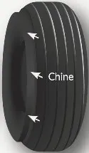
Aircraft Tyre are design with chines in nose wheel to divert runway water.
Treading- Tread is the outer most part of the tyre and it is made of rubber with some composite materials.
Ply- Ply is the synthetic fabric, which is used for the reinforcement of the tread or rubber and the multiple layer of ply used in order to increase strength of tyres.
Filling Gas- In order to withstand high temperature, inert gas like nitrogen are used in the aviation industries tyres.
Rolling Resistnce- like all vehicles the friction between tyre and runway is proportional to the normal force exertedby the aircraft.
`F=mu(W-L)`
Normal force will be the difference between weight of aircraft and lift. and rolling resistance coefficient is usually in the range of 0.02 in the runway of aircraft.
Tyre pressure- Tyre pressure in the aviation industries are usually more than 200psi (inflation 220psi fir Boeing 777-300) and upto 400psi depending on the applicaton and weight of the aricraft. Aircraft tyre is made to easily withstand 800psi of inflation.
Brake Force when landing- Braking is nothing but the reduction of speed of the aircraft. brakes converts kinetic energy into heat energy to reduce the aircraft speed, Brakes provide this critical stopping function during landings to enable aircraft to stop within the length of the runway.
At landing The aircraft (say Airbus A320, weight 77 metric tons) the speed of the aircraft is usually 250km/h and as soon as its tyre touch the ground and apply a certain force at the wheels(6300kg), The Brakes fla apply followed by thrust reversal. The actual brake are used as the third brake system. so after aircraft reached 140 km/h speed then the disc brakes are applied and usually create high temperature (200C)
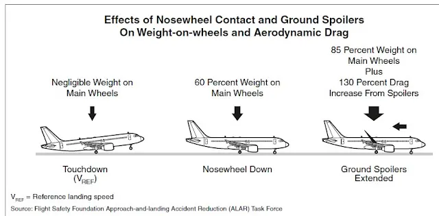
modern Aircraft use Disc brakes with electro-mechanical actuators to have better braking and reliability.
Part B-
6[A]-
To Push-Pull the aircraft the towing vehicle needs to provide enough power to pull/push the aircraft weight and huge inertia with the same forces acts on the vehicle and aircraft both.
for understanding purpose, in this case we consider Airbus A320 with total weight of 77 metric tons and we consider rolling resistance coefficient of 0.02 and air drag coefficient of 0.25 approximetly(both aircraft and towing vehicle).
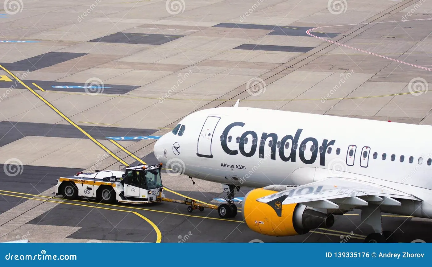
now make a table with all asumtion parameters.
| 1. | Aircraft total weight | 77000 kg |
| 2. | Towing vehicle weight | 20000 kg |
| 3. | Rolling resistance coefficient (mu) | 0.02 |
| 4. | Airdrag coefficient (Cd) |
0.25 |
| 5. | Frontal area |
15 m^2 |
| 6. | max aceleration required | 2 m/s^2 |
so we calculate the fgollowing forces acting on the vehicle,
Rolling resistance Force, `Frr= mu *m*g`
Air Drag Force, `Fad=1/2rho *A*Cd*V^2`
Acceleration Power, Acc Force = m*a
Acc power = `(Delta K.E.)/t`
= `1/2*m*((V^2-0^2)/t)` {from rest to V velocity}
Now make a exel file for all calculations,
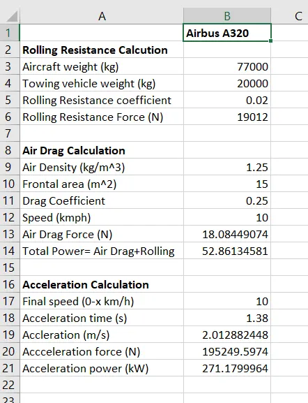
Here we can see for accelerating the towing vehicle (with Airbus A30) for 0 to 10 km/h with amost 2 m/s^2 acceleration we need Total power of = 52.86+271.18 = 324.04 kW (rolling resistance+ airdrag+acceleration).
and the total force required is = 19012+18.08+195249 = 214,279 Newtons.(approx.)
6[B]-
Here we consider following points
1. There are Rolling resistance and Air drag force both forces work on vehicle continuesly but accelerating force required by vehicle is the function of inertia of the vehicle system.
2. In starting, the inertia is in rest position so accelerating force requires is high but at the final velocity 10 km/h (2.7778 m/s) the vehicle is moving at final velocity in support with inertia so there are no more accelerating force required.
3. unlike accelerating force the accelerating power is calculated by considering total energy given by the motor to accelerate the vehicle. It is calculated seperately because at starting the instaneous power is zero (ie. F*V) and at final velocity the instantaneous power is maximum but to calculate actual power required, we have to take average of these values.
Now develope the simulink model.
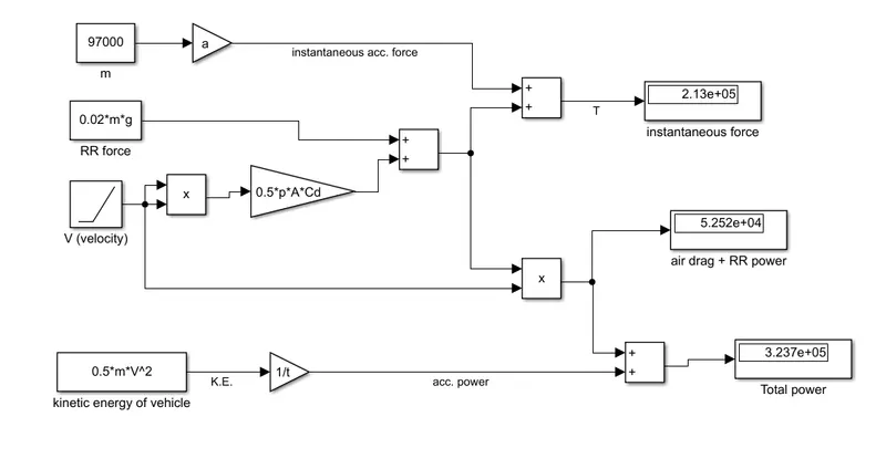
The up most part is the force required for acceleration ie. F=ma, and it is required as long as there is acceleration present is the vehicle. second part is Rolling resistance force and air drag force which is calculated by implementing following formulae
Rolling resistance Force, `Frr= mu *m*g`
Air Drag Force, `Fad=1/2rho *A*Cd*V^2`
here we take V(velocity) as 10 km/s(2.77778 m/s) with the ramp slop of 2 (acceleration m/s^2) the final velocity achieve at t=1.38sec. therefore we run the simulation for t=1.38 secs. then this force is added with the acceleration force and total thrust required by aircraft will be calculated(T in newtons).
Air drag power and Rolling Resistance (RR) power is calculated with following equation
P = F*V (which is continous)
and the accelerating power is implemented by following equation,
Acc power = `(Delta K.E.)/t`
= `1/2*m*((V^2-0^2)/t)` {from rest to V velocity}
then both powers are added with Add block and we got the total power required by the Towing vehicle in order to push/pull the Airbus A320. (213kN,323.7kW)
7[A]-
Aim- Design an electric powertrain with type of motor, it’s power rating, and energy requirement to fulfill aircraft towing application in Simulink. Estimate the duty cycle range to control the aircraft speed from zero to highest. Make all required assumptions. Prepare a table of assumed parameters. Draw a block diagram of powertrain.
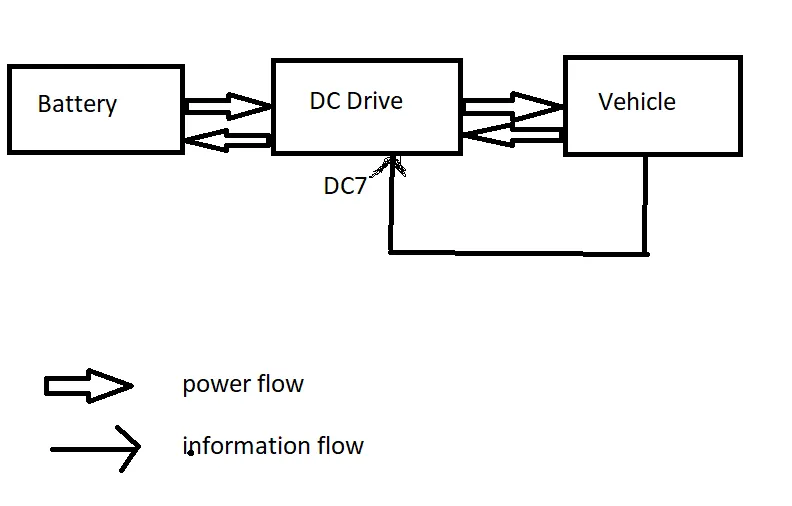
Method to strike- first we have to decide how we gonna make a model to achieve the goal. so as per Hint we use DC7 block. there are several advatages when we use DC7 block as it is a Four quadrant chooper and it directly gives the Duty cycle of converter circuit for a certain load demand.
DC7 chopper is fully automated DC Drive, and we do not to worry about implementing the control circuit but we follow the application oriented simulation to see the results.
while using DC7 block we can only have motor speed output and we have to give Torque as a feedback, so in order to do that we use Vehicle force model to calculate the Force required by the vehicle and then we convert this force to Torque as per radius of wheel and gear ratio.
DC7 Drive is supplied by a lithium-ion batterypack with 520V nominal voltage and 100Ah battery capacity, which is detailed matlab model that auto adjust their charging and discharging parameters according to the specification of battery.
Block Diagram of power train-
Calculations-
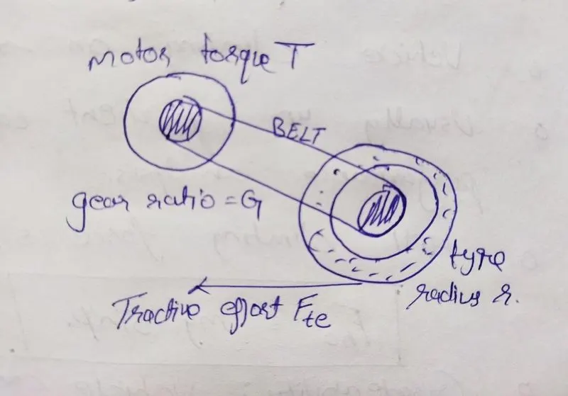
The speed of motor is available at the output of the DC7 Drive block, this speed is then converted into velocity of vehicle by following equation,
`V=r/G*omega`
where, r & G are the radius of driving wheel and nominal gear ratio.
then the vehicle forces that is rolling resistance and airdrag forces is added to calculate the force required to run the vehicle.
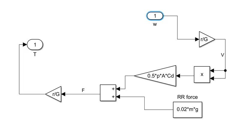
after that the force is converted into torque required by the motor by following equation,
`T=(F*r)/G`
Now at the model for a sec.
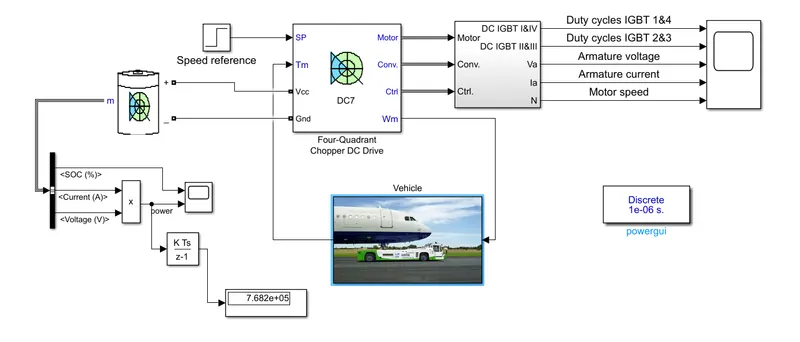
Here we can see that the model is made with the DC Drive (DC7) and all necessary blocks with a battery which voltage and current will give the power taken by the model.
Here we take initial velocity zero to the final velocity V=15 km/h (4.167 m/s) that gives equivalent the motor speed,
`omega=G/r*V`
`omega=15/0.6*4.167`
`omega=104.175`
and the speed in rpm
N=`(104.175xx60)/(2pi)`
N= 995 rpm
so we specify the DC7 block parameters,
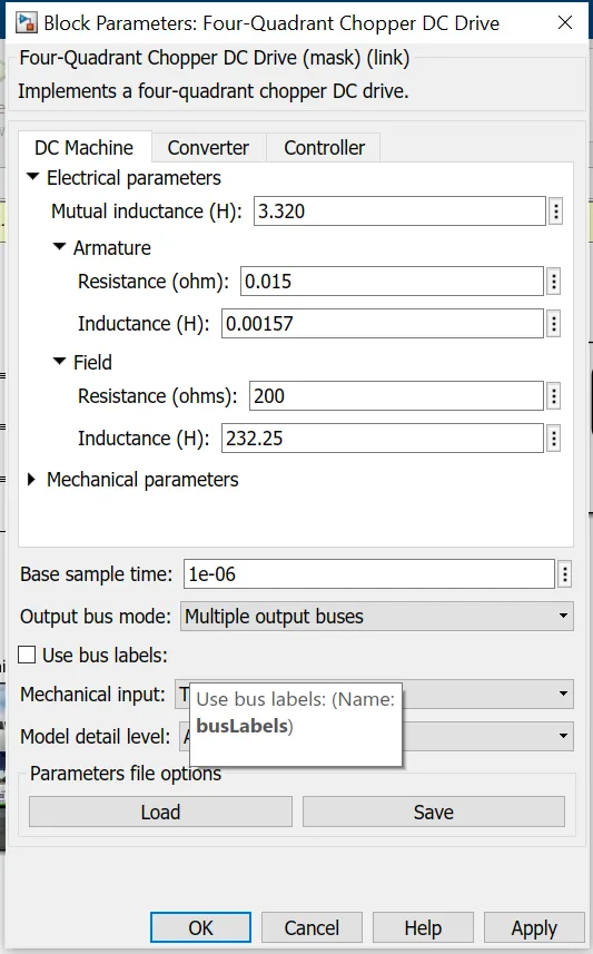
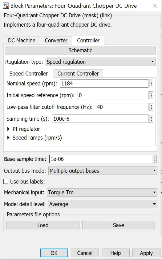
now we run the model with average model model setting to visualise the output of the model
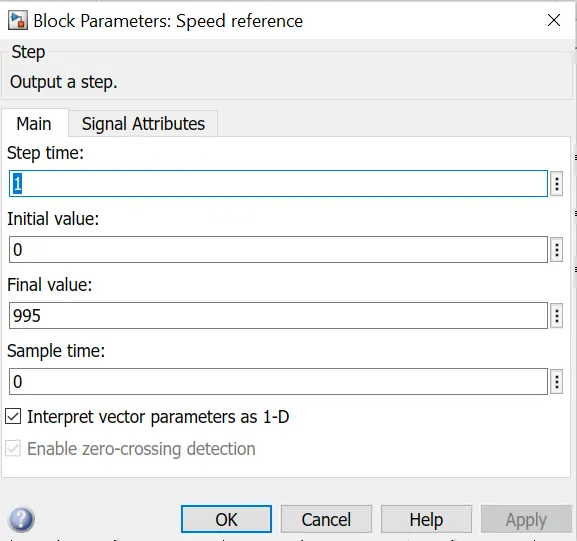
we take speed reference as a step signal as following cofiguaration
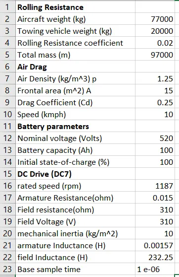
we now make a table for all assumed parameters
Results-
Now take a look at results,
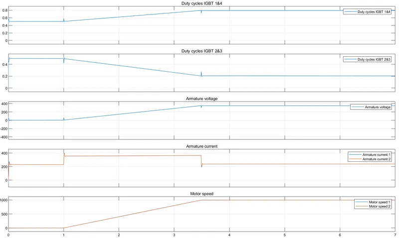
Here we can see that the speed of motor is almost zero(other than some constant losses) untill 1 sec after that speed starts to increase and duty cycle of the forward sswitches(1&4) increases from 0.5 to 0.8 (aprox.) and the reverse switches(2&3) duty cycle is change by 0.5 to 0.2 so that the output voltage(ie. around 400V) is such that motor will run at 995 RPM.
Now see at the power required for this operation which is battery current and voltage.
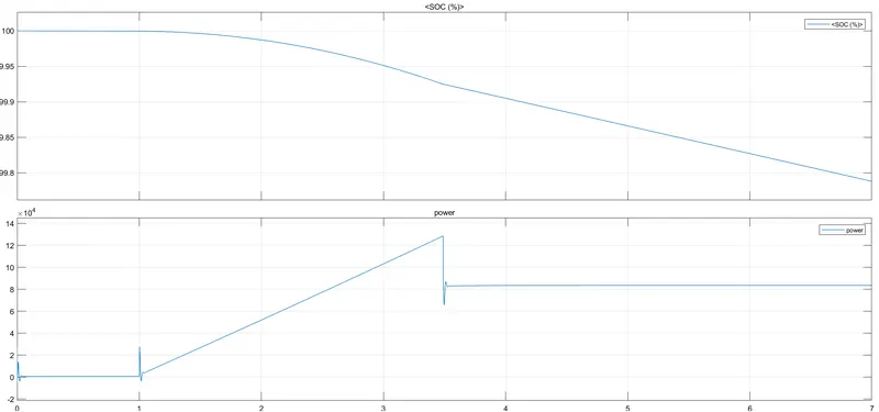
The power from battery is zero untill 1 sec as there is no work done but after that power increases and gone to 130kW max and then return to the 80kW to maintain the speed of 15 km/h and the total energy required for 7sec of simulation will be 455.3 Joules and battery SoC after this operation is around 99.8%.
7[B]-
parameters in Excel sheet is attached.