Project-1: Powertrain for aircraft in runways
Part A:
- Search and list out the total weight of various types of aircrafts.
- Is there any difference between ground speed and air speed?
- Why is it not recommended to use aircraft engine power to move it on the ground at Airport?
- How an aircraft is pushed to runway when its ready to take off?
- Learn about take-off power, tyre design, rolling resistance, tyre pressure, brake forces when landing.
Part B:
6. a.With necessary assumptions, calculate the force and power required to push / pull an aircraft by a towing vehicle.
b.Develop the model for the calculated force and power using Simulink.
7.a. Design an electric powertrain with type of motor, it’s power rating, and energy requirement to fulfil aircraft towing application in Simulink. Estimate the duty cycle range to control the aircraft speed from zero to highest. Make all required assumptions. Prepare a table of assumed parameters. Draw a block diagram of powertrain. (Hint: DC7 Block)
b.Also, Design the parameters in excel sheet.
AIM:
- Search and list out the total weight of various types of aircrafts:
The vehicle which is manufactured to fly in the air is called an aircraft. All these have the propellers and wings or machinery to run through the air; however, they may vary according to sizes, types, usage, and more.
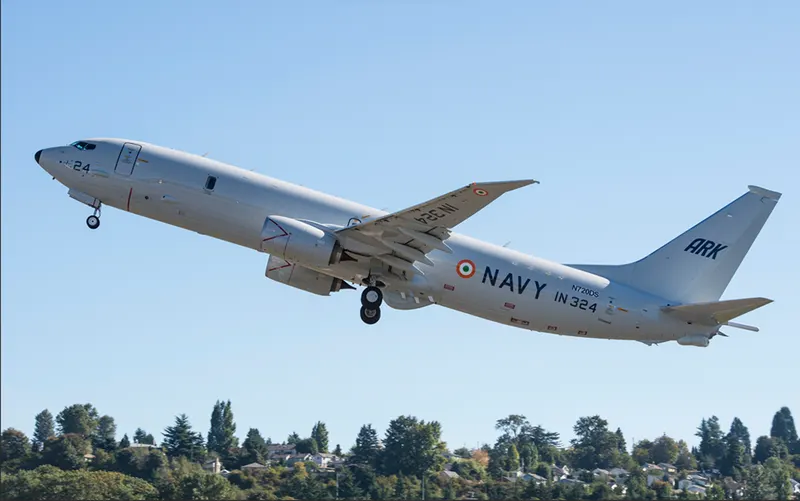
There are various types and categories of Airplanes and Helicopters are the most common types of aircrafts we may know. But what you may miss out on are different and several other categories in aircraft that you may not know. airplane from light to heavy and having different load capacities. Some of the airplanes are listed below, and also from helicopters to gliders to cargo planes, fighter jets, balloons, and more, there are numerous other aircraft types and categories. Some of them are
|
S.no |
Aircrafts types |
MTOW |
MLW |
MAX Speed |
|
1. |
Antonov An-225 |
640,000 |
591.7 |
800kmph |
|
2. |
Airbus A300 |
192,000 |
140 |
847kmph |
|
3. |
Boeing 747-8 |
443,613 |
306.175 |
988 kmph |
|
4. |
Boeing 747-400 |
396,900 |
295.742 |
988 kmph |
|
5. |
Boeing 777 |
347,800 |
260.816 |
950 kmph |
|
6. |
Concorde |
185,000 |
111.1 |
2179 kmph |
|
7. |
Bombardier Q400 |
28,000 |
28.01 |
667 kmph |
|
8. |
Boeing 757-200 |
116,000 |
89.9 |
982 kmph |
|
9. |
McDonnell Douglas MD-83 |
73,000 |
63.28 |
874 kmph |
|
10. |
Fokker 100 |
46,000 |
39.95 |
856 kmph |
|
11. |
Embraer E-190 |
48,000 |
43 |
950 kmph |
|
12. |
Pilatus PC-24 |
8,300 |
7.665 |
787 kmph |
|
13. |
Lear jet 75 |
9,752 |
8.709 |
1000 kmph |
|
14. |
Mil Mi-26 |
56,000 |
295 kmph |
|
|
15. |
Bell Boeing V-22 Osprey |
27,445 |
509 kmph |
Here MTOW = Maximum take-off weight, MLW = Maximum landing weight, MAX Speed = Maximum Speed.
These are the name of few aircraft having specification about their different weight in Ton and max speed.
Maximum Landing Weight
The maximum landing weight (MLW) is the maximum aircraft gross weight due to design or operational limitations at which an aircraft is permitted to land. The operation landing weight may be limited to a weight lower than the maximum landing weight by the most restrictive of the following requirements. Aircraft also have a maximum take-off weight (MTOW) which is almost always higher than the maximum landing weight, so that an aircraft can weigh less upon landing due to burning fuel during the flight
- Aircraft performance requirements for a given altitude and temperature
- landing field length requirements,
- approach and landing climb requirements.
- Noise requirements
Maximum Take-Off Weight
The maximum take-off weight (MTOW) or maximum gross take-off weight (MGTOW) or maximum take-off mass (MTOM) of an aircraft is the maximum weight at which the pilot is allowed to attempt to take off, due to structural or other limits. It is the heaviest weight which should be limited in order to ensure the aircraft can fly safely during take-off. The analogous term for rockets is gross lift-off mass, or GLOW. MTOW is usually specified in units of kilograms, or pounds. regulated take-off weight", varies according to flap setting, altitude, air temperature, length of runway and other factors. It is different from one take-off to the next, but can never be higher than the MTOW.
Here MTOW is the heaviest weight at which the aircraft has been shown to meet all the airworthiness requirements applicable to it. MTOW of an aircraft is fixed and does not vary with altitude, air temperature, or the length of the runway to be used for take-off or landing. At its MTOW an aircraft compiles with all the structural and performance requirements. This MTOW of the aircraft is fixed.
- Is there any difference between ground speed and air speed?
Ground speed:
Ground speed is simply the sum of airspeed and wind speed. If the aircraft is flying in the same direction as the wind is blowing, the aircraft experiences tailwind, and its ground speed is higher than its airspeed. It is the horizontal speed of an aircraft relative to the ground. It is vital for accurate navigation that the pilot has an estimate of the ground speed that will be achieved during each leg of a flight. An aircraft heading vertically would have a ground speed of zero. For a reference point picked on the ground, the aircraft moves relative to the reference point at the ground speed to the wind speed must be done according to rules for vector comparison.
It is measured using GPS, and indicated airspeed is measured using sensors on the plane called pitot tubes. Its speed relative to ground.
Ground speed can be determined by the vector sum of the aircraft’s true airspeed and the current wind speed and direction.
a headwind subtracts from the ground speed, while a tailwind adds to it. Winds at other angles to the heading will have components of either headwind or tailwind as well as a crosswind component.
Air speed:
airspeed is simply the speed at which an aircraft is moving relative to the air it is flying in. As such, it’s also the speed at which the air is flowing around the aircraft’s wings. Its speed relative to air. the common conventions for qualifying airspeed are,
indicted airspeed (IAS), calibrated airspeed (CAS), equivalent airspeed (EAS), true airspeed (TAS), and density airspeed.
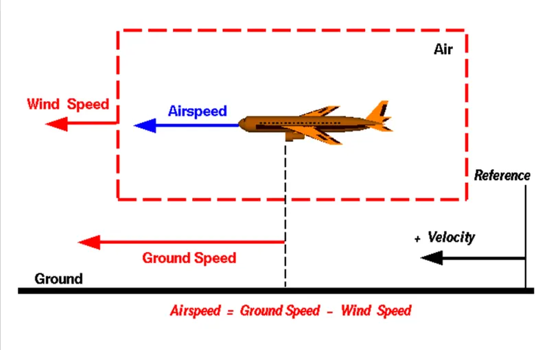
Airspeed cannot be directly measured from a ground position, but must be computed from the ground speed and the wind speed. Airspeed is the vector difference between the ground speed and the wind speed.
Airspeed = Ground speed – Wind speed
So, the main difference between the Ground speed and Air speed is the relative speed with respect to a reference point, where the Ground speed is the relative speed with reference a point on ground while the Airspeed is the relative speed with reference to the air medium in which it flies.
- Why is it not recommended to use aircraft engine power to move it on the ground at Airport?
As we known that the gross weight of the aircraft is high, which is hundreds of tons and it differ from one aircraft to another. to move the aircraft from one place to another it will require a huge amount of power which is produced by the aircraft engines. But, to move the aircraft from hanger to the parking space where the passengers may embark on the plane, by using the aircraft engine is not economical and safe.
To move the aircraft for shorter distance such as moving to places from hanger to parking bay if we use aircraft engine power, it consumes a lot of costly fuel which is not advisable and mostly It seems most danger to run that much of huge engine to run on ground with unlimited speed. Some of the reasons that we can identify to not to use aircraft engine power on ground are,
- The engine creates a space where any equipment can suck or pulled into engine if anything is too close to it when it is running.
- Flammable materials or oils or gases which is near get observed and get blast because of rupture speed which can get heat around it.
- The noise obtained from the plane is higher which may affect human and also the animals’ ears and body due to high decibels sound. And also fumes gave more heat.
- People and things can damage if they are near to the plane. Because air intake is very powerful which it forms like a little cyclone which can suck human bodies easily.
- The engine outlook or body my get damage due to ground force or by any other causes.
- Due to this high suction force the small particles near to the engine like dust particles, stones, papers, plastic etc pulls to the engine which may damage the engine or its parts.
- . Also, this will cause a lot of pollution and carbon emission and noise pollution etc.
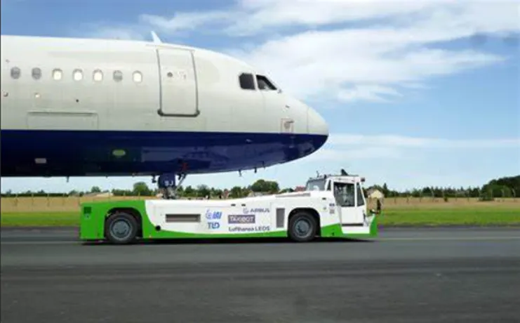
This is why, we utilize a tow tractor to move aircraft from one place to another for shorter distances.
- How an aircraft is pushed to run away when its ready to take off?
The aircraft is pushed onto a runway with the help of a towing vehicle also known as tow tractor when it is ready for take-off.
Taxi-Ing the aircraft involves moving it along the ground from where it has been parked, up to the start of the runway. During taxi-Ing, there are other checks which need to be done, mainly to ensure that the steering on the ground works as it should do.
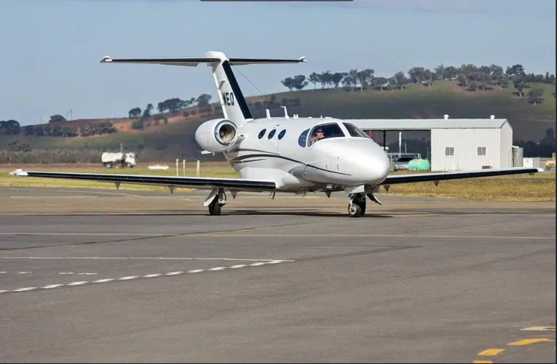
taxiing
When the pilot calls ‘ready for departure’, there are several possible answers he could get from Air Traffic Control. He may be asked to hold his position, especially if other aircraft are waiting to take off. He may be asked to ‘line up and wait’, which means he can taxi to the start of the runway, and position the aircraft ready to move down the runway or the take-off role. The take-off rolls or ground roll is the portion of the take-off procedure during which the airplane is accelerated from a standstill to an airspeed that provides sufficient lift for it to become airborne. But if anything seems wrong during the take-off roll, the pilot will abort the take-off, which means he will apply the brakes and come to a halt on the ground before the end of the runway. Aborted take-offs happen to all aircraft, large and small, though quite rarely.
Pushback is an airport procedure during which an aircraft is pushed backwards away from an airport gate by external power. Pushbacks are carried out by special, low-profile vehicles called pushback tractor or tugs.
Although many aircraft are capable of moving themselves backwards on the ground using reverse thrust, the resulting that might cause damage to the terminal building or equipment. Engines close to the ground may also blow sand and debris forward and then suck them into the engine, causing damage to the engine. A pushback is therefore the preferred method to move the aircraft away from the gate.
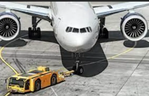
Pushback at busy aerodromes is usually subject to ground control clearance to facilitate ground movement on taxiways. Once clearance is obtained, the pilot will communicate with the tractor driver to start the pushback.
Since the pilots cannot see what is behind the aircraft, steering is done by the pushback tractor driver and not by the pilots. Depending on the aircraft type and airline procedure, a bypass pin may be temporarily installed into the nose gear t disconnect it from the aircraft’s normal steering mechanism.
Once the pushback is completed, the towbar is disconnected, and any bypass pin removed. The ground handler will show the bypass pin to the pilots to make it clear that it has been removed. The pushback is then complete, and the aircraft can taxi forward under its own power.
the take-off is an important part of flying. It is usually not difficult, but there are many things which can go wrong. So, the take-off should be treated with care and caution to ensure a safe flight.
- Learn about take-off power, tyre design, rolling resistance, tyre pressure, brake forces when loading:
Take-off Power:
A normal take-off is one in which the airplane is headed into the wind, or the wind is very light. Fr aircraft traveling vertically, which is known as lift-off. If the aircraft that is take off horizontally, this usually Involves starting with a transition from moving along the ground or runway. Also, the take-off surface is firm and of sufficient length to permit the airplane to gradually accelerate to normal lift-off and climb-out speed, and there are no obstructions along the take-off path. Usually, the engines are run at full power during take-off.
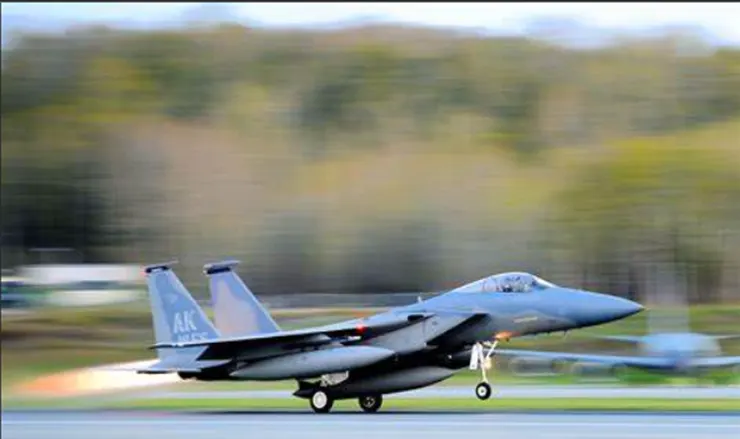
Take-off is the phase of flight in which an aerospace vehicle leaves the ground and becomes airborne. The take-off and initial climb are two of the most critical safety phases of the aircraft flight. The combined analysis of both phases is referred to as the aircraft take-off performance. Take-off performance can be predicted using a simple measure of the acceleration of the aircraft along the runway based on force equilibrium.
The forces involved will be,
T – Thrust of propulsion system pushing aircraft along runway.
D – Aerodynamic Drag of vehicle resisting the aircraft motion.
F – Rolling resistance friction due to the contact of wheels or skids on the ground.
During take-off run the imbalance in these forces will produce an acceleration along the runway.
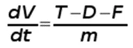
Where ‘dV/dt’ is the acceleration along the runway and ‘m’ is the mass of the vehicle.
For light aircraft, usually full power is used during take-off. Large transport category (airliner) aircraft may use a reduced power for take-off, where less than full power is applied in order to prolong engine life, reduce maintenance costs and reduce noise emissions. In some emergency cases, the power used can then be increased to increase the aircraft's performance.
The take-off distance consists of two parts, the ground run, and the distance from where the vehicle leaves the ground to until it reaches 50 ft (or 15 m). The sum of these two distances is considered the take-off distance.
There are four forces which helps the aircraft to take off:
- Thrust: It is a force that moves an aircraft in the direction of the motion. It is created with a propeller, jet engine, or rocket. Air is pulled in and then pushed out in an opposite direction. One example is a household fan.
- Drag: It is the force that acts opposite to the direction of motion. It tends to slow an object. Drag is caused by friction and differences in air pressure. An example is putting our hand out of a moving car window and feeling it pull back.
- Weight: It is the force caused by gravity.
W = mg
- Lift: It is the force that holds an airplane in the air. The wings create most of the lift used by airplanes.
The main points to remember by these forces are,
If Thrust is greater than drag, the plane moves forward.
If Drag is greater than thrust, the plane moves backwards.
If Lift is greater than Weight, the plane moves upwards.
If Weight is greater than Lift, the plane stays on the ground and can’t fly.
Therefore, Take-off power = total force * Velocity
For smaller aircrafts like turboprop, we use full power for take-off.
Because they don’t have take-off power settings. But in aircrafts like Jet plane, they take-off power settings so they don’t have to take the full power.
Tyre Design:
Designing aircraft tires is a very intense undertaking. The tyre is designed to withstand heavy loads while landing, take-off, taxing, and parking. An essential part of aircraft tire design, Finite Element Method (FEM) technology is utilized to predict tire component stress-strain and heat generation characteristics. The number of wheels required for aircraft increases with the weight of the aircraft as the weight of the aeroplane needs to be distributed more evenly. Tyres are critical components of aircraft. The choice of tyre totally depends on the aircraft manufacturer. Aircraft tyre generates more heat during landing. Aircraft drags the wheel until they match the rotational velocity of wheels. Due to this heat generates. However, each tyre is built to operate within a given temperature. This is known as vulcanization temperature. During the course of its use, if the tyre is heated past the vulcanization temperature, it begins to wear gradually.
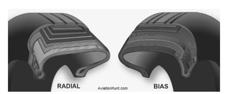
Two types of tires are used in an aircraft application: bias-ply tires and radial tires.
The basic difference between a radial tyre and bias (cross-ply) tyre is the lay of the plies within the tyre carcass. The remainder of the tyre is very similar in construction in both.
Radial Tyre:
Radial tyres having a feature of rigid belt and flexible carcass which providing a greater number of landings and less rolling resistance. It has fibre stands of the ply fabric oriented at 900 to the direction of radiation and the tyre sidewall. This restricts flexibility bidirectional and the flexibility of the sidewall while it strengthens the tyre to carry heavy loads. Due to their unique construction most, radial tyres are resistant to penetration ad cuts. Due to stiffer tread, they distribute weight evenly. Thus, provide greater traction. Radial tyres have an advantage in term of reducing the heat better. It can only a small portion of the radial tyre will be affected in case of any damage in this type. these tyres have the word RADIAL on the sidewall.
Bias-ply Tyre:
It has the fabric bias oriented with and across the direction of rotation and the sidewall. Since fabric can stretch on the bias, the tyre is flexible and absorb loads. Tyre strength is obtained by adding piles. It is cut resistant is sidewall area. These tyres do not offer as much smoothness in terms of riding quality. More than in air craft this use in heavy-duty carriage trucks and buses. The one of the best advantages in this type method is that if there is any cut in the tread area, it can affect only a small portion of tyre.
Today Almost all airliners are using Radial tyre. Bias is an older design, and it’s mainly used for road vehicles. Radial tires are more expensive than bias-ply tyres. Radial tires are in demand because of their lower life cycle cost and long-term value.
Rolling Resistance:
The force that resists the motion of a body rolling on a surface is called the rolling resistance or the rolling friction.
The rolling resistance can be expressed as
Fr = c W /r
where Fr = rolling resistance or rolling friction (N)
c = rolling resistance coefficient
W = m * ag
m = mass of body (kg, lb)
ag = acceleration of gravity (9.81 m/s2)
r = radius of wheel (mm, in)
Rolling resistance, sometimes called rolling friction or rolling drag, is the force resisting the motion when a body (such as a ball, tire, or wheel) rolls on a surface. It can be seen in the aircraft takes off from the runway and while landing at the runway with the help of other wheels. The friction between aircraft and runway will be proportional to the normal force exerted by the aircraft on the runway.
F=µ(W-L)
The normal force will be the difference between Weight(W) of aircraft and lift (L), the friction coefficient (µ) will be typically of a magnitude of 0.02 for a standard tarmac runway.
It is the force resisting the motion when a body rolls on the surface. It can be observed in the aircraft when its take-off from the runway and while landing at the runway with their wheels.
Tyre Pressure:
- Aircraft tyres operate at such high extremes of pressure, load, and speed, their care and service are critically important for the short durations. It’s generally operated at high pressures, up to 200 psi (14 bar; 1,400 kPa) for airliners, and even higher for business jets. The main landing gear on the Concorde was typically inflated to 232 psi (16.0 bar), whilst its tail bumper gear tires were as high as 294 psi (20.3 bar). So, The most important action an operator can take to prevent tyre-related events is to maintain proper tire inflation pressure. The no of tyre required for aircraft increases with the weight of the aircraft, as the weight of the airplane needs to be distributed more evenly. If we fail to keep aircraft tires properly, inflated can lead to very serious consequences. One relatively easy way to help avoid those consequences is to check tire pressures regularly and service them as necessary. Tyres and tubes should be stored in a cool, dry place out of direct sunlight.
Following by these actions we may get the most value out of your tires and contribute to the safe operation of your aircraft.
- Perform daily pressure checks with a calibrated gauge.
- Target the highest pressure recommended in the AMM or POH (105 percent of operating pressure).
- Care should be taken that tires do not come in contact with oil, gasoline, jet fuel, hydraulic fluids or similar hydrocarbons. Rubber is attacked by these in varying degrees.
- tires should be stored vertically on tyre racks.
- When tyres are going to be subjected to ambient temperature differences between two locations in excess of 27°C, inflation pressures should be adjusted to the colder temperature prior to take-off
- Inaccurate gauges are a major source of improper inflation pressures. Gauges should be checked periodically and recalibrated as necessary.
Rated pressure is the maximum inflation pressure to match the load rating. Temperatures should be between 0°C and 30°C. Aircraft tire pressures are given for an unloaded tire; i.e, a tire not on an airplane. When the rated load is applied to the tire, the pressure increases by 4% as a result of a reduction in air volume. Each tyre pressure gauge is calibrated to an accuracy of +/-1% allowing optimum aircraft tyre pressure settings to be achieved.
The 100mm pressure gauge dial face allows instant visibility of the tyre pressure making the operators task very efficient in any environment.
There are three major factors that affect tyre performance they are,
- Centrifugal force.
- Heat generation.
- Tensile, Compression and Shear Forces.
Brake force when landing:
Aircraft brakes stop a moving aircraft by converting its kinetic energy to heat energy by means of friction between rotating and stationary discs located in brake assemblies in wheels. As now All modern commercial aircraft have automatic brake systems. Just like a car, these systems also have an anti-lock braking system (ABS) that prevents the tires from sliding down a wet runway. Stopping a 200-tonne aircraft landing at 180 mph requires a lot of braking force. Bringing an aircraft down to the runway from 37,000 feet is one part of the challenges. It’s over until the aircraft is safely parked at its gate.
To do this either hydraulic brakes or electric brakes are used. Brakes provide this critical stopping function during landings to enable airplanes to stop within the length of the runway.
And here Hydraulic brakes put on weight of the circuit to stop the plane. Now a days designers use electric brake system. The aim of brake force when landing is to minimise the distance. For that A large amount of brake is required to stop the aircraft after landing on the runway since the speed of the aircraft is quite high in the range of 250-300 kmph. In order to calculate the brake force required to stop the aircraft, we have to first estimate the kinetic energy carried by its mainly used for the electrical breaking as well and this can be determined by,
E = ½. m.v2
Actually, aircraft breaks are two types
Steel brakes
Steel brakes were used for years as standard in the aviation sector. They are relatively heavy and can only withstand temperatures up to 2,000°C (3,600°F). They must be replaced after an average of 1,000 landings.
Carbon brakes
Carbon brakes have become the standard on newer aircraft in the meantime. They are considerably lighter than steel brakes. Now the steel is replacing with carbon breaks. they are much sturdier, having the ability to withstand temperatures of up to 3,000°C (5,400°F). Even the service life is longer. Carbon brakes can handle 2,000 landings on average. But carbon brakes are more expensive than steel brakes.
Aircraft braking systems includes some other terms are:
- Disc brakes in the landing gear used to break the wheels while touching the ground. These are operated hydraulically or pneumatically. In most modern aircrafts they are activated by the top section of the rudder pedals.
- Thrust reverse allow thrust from the engines to be used to slow the aircraft.
- Air brakes work by increasing air drag on the flight surface.
In construction of aircraft breaks, A major design point around which aircraft brakes are designed is the worst-case scenario of rejected take-off (RTO) at the maximum rolling speed.
- A. With necessary assumptions, calculate the force and power required to push / pull an aircraft by a towing vehicle:
B. Develop the model for the calculated force and power using Simulink:
Towing vehicle: the vehicle which hangers or attached to the aircraft front vehicle to move forward or backward in the airport usually with engines off. The ground vehicle attached to or supporting the nose wheel is towing or tug. These aircraft nose is attached to the tow vehicle by the use of towbar or other specialised methods. It is used for the movement of both in service and out of service aircraft.
The forces required to push / pull an aircraft by a towing are rolling resistance force and aerodynamic drag force.
Rolling resistance force: - Rolling resistance force is the force resisting the motion when a body (such as a ball, tire, or wheel) rolls on a surface.
Its governing equation or the equation of rolling resistance is given as
Frr = Crr*m*g
were,
Frr = force of rolling resistance.
Crr = Rolling resistance coefficient.
m = Mass of the body.
g = acceleration due to gravity.
2)Aerodynamic Drag Force: - the force which resists the motion of a body with air is called aerodynamic drag force.
The equation for this aerodynamic drag force is,
Fd = ρϑ2CDA
were,
Fd = drag force
ρ = density of the air
ϑ = flow velocity relative to the object
Cd = drag coefficient
A = reference area
Calculation: -
For calculation
Let us assume some calculating parameters,
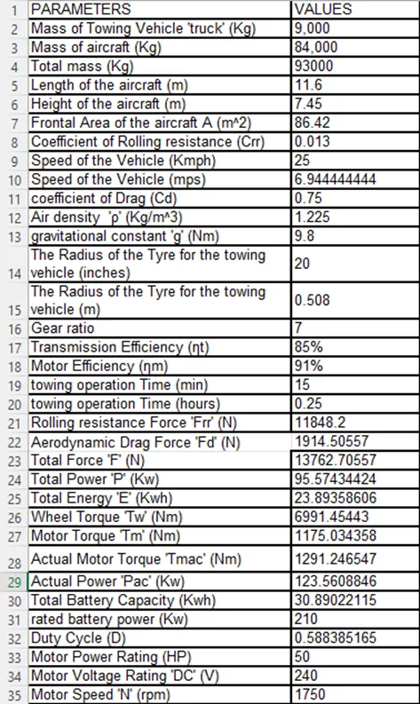
Mass of the truck (Towing Vehicle) = 9,000 kg
Mass of aircraft = 84,000kg
Total mass(m) = 9000+84000=93,000kg
Length of the aircraft = 11.6 m
Height of the aircraft = 7.45 m
Frontal Area of the aircraft (A)= 86.42 m2
Speed of the truck (towing vehicle) = 25Kmph
Converting it into m/sec
ϑ= 25 * (1000/3600) =6.9445 m/sec
Drag coefficient (Cd) = 0.75
Air density (ρ) = 1.225kg/m3
Rolling resistance coefficient (Crr) = 0.013
Gravitational constant (g) = 9.8 Nm
Taxing time = 15 mins (time used to take or move the aircraft to particular location)
= 15/60 hrs
= 0.25 hrs
Calculating Rolling resistance Force (Frr) = Crr*m*g
=0.013*93,000*9.8
Rolling resistance Force (Frr) =11848.2 N
Calculating Aerodynamic Drag Force (Fd) = 0.5*ρ*Cd*A*v^2
=0.5*1.225*0.75*86.42*6.9445^2
Aerodynamic Drag Force (Fd)=1914.5 N
Therefore, the total force required to push/pull he aircraft by the towing vehicle
(F) = Frr+Fd
=11848.2 + 1914.5
=13762.7 N
Calculating the power required to run the vehicle
Power (p) = Force*Velocity
=13762.7*6.9445
=95.575kW
Energy required for towing to move the aircraft,
Energy (E)= total power * time in hrs
= 95.575 * 0.25
= 23.893 Kwh
B.Developing the model for the calculated force and power using Simulink: -
To develop the model for the equation that we calculated above we use some Blocks the that we Blocks Used are,
1)Constant
2)Sum
3)Product
4)Square
5) Gain
6) Display
Simulink Model: -
The model of the Simulink for the Force, Power and Energy is look like as below,
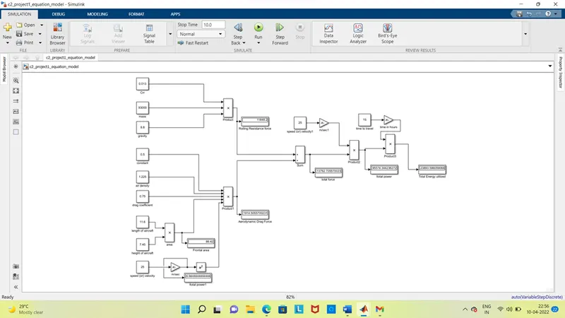
Explanation: -
In order to understand the above Simulink model, we have to observe the equation from the start.
- To calculate the value of rolling resistance force (Frr) we used product block to multiply the values Crr which is coefficient of rolling resistance, mass(m) & gravity (g)which are to be entered in the Constant block.
- Similarly for calculating Aerodynamic Drag force (Fd) we have to multiply the Air density, drag coefficient, Frontal area of aircraft (A), velocity in m/sec from kmph which is converted by the gain block with value (5/18) and a constant value 0.5 which are to be entered in constant block with the product blocks.
- For calculating power, we have to multiply both total force (F) which is the addition of the rolling resistance force (Frr), and Aerodynamic Drag force (Fd) by sum block and velocity in m/sec for this we have used product block (P=F*V)
- For the energy we multiplied the power with the time in hours by the product block.
- In order to convert velocity in Kmph to m/sec we have multiplied it with 5/18 by using the gain block.
- For squaring uses square block.
- To convert time from minutes to hours we used the gain block with the value (1/60)
- To see the answers, we used the display block which is used to see the numerical values.
- A.Design an electric powertrain with type of motor, it’s power rating, and energy requirement to fulfil aircraft towing application in Simulink. Estimate the duty cycle range to control the aircraft speed from zero to highest. Make all required assumptions. Prepare a table of assumed parameters. Draw a block diagram of powertrain. (Hint: DC7 Block)
B.Also, Design the parameters in excel sheet.
Based on the calculations done in 6A.
Force required to push/pull the aircraft = 13762.7 KN
Power required = 95.575 Kw
Energy required = 23.893 Kwh
Let us assume some other required parameters,
The Radius of the Tyre for the towing vehicle = 20 inches = 0.508 m
Gear ratio = 7
Transmission Efficiency (ηt) = 85%
Motor Efficiency (ηm) = 91%
calculation,
Torque required for the wheels (Tw)
Tw = Total Force * Tyre Radius in meters
= 13762.7 * 0.508
Wheel torque Tw = 6991.45 Nm
Torque required for motors (Tm)
Tm = Wheel torque / (Gear ratio*ηt)
= Tw / (Gear ratio*ηt)
= 6991.45 / (7*0.85)
Motor torque (Tm) = 1175 Nm
Actual motor torque (Tmac)
Due to some losses in the motor torque because of the mechanical equipment or friction or rotational losses it takes more torque so their efficiency become less let’s take example (91%)
Therefore, the actual motor torque.
Tmac = motor torque / motor efficiency
= Tm / ηm
= 1175 / 0.91
= 1291.2 Nm
Similarly, the actual power required by the motor also changes due to the losses because of all these losses it requires more power so the efficiency of this motor power is reducing which is 77% (0.85*0.91).
Therefore, the actual power is,
Pac = Total power / total efficiency
= 95.575 / (0.85*0.91)
= 95.575 / 0.77
= 124.123 Kw
Total battery capacity:
The total energy consumed also called as a battery capacity which is the product of the total actual power required for the vehicle with time in hours.
Total battery capacity = total actual power required * time in hours
= 124.123 * 0.25
= 31.03 Kwh
So, the battery capacity for this condition is the 31.03 Kwh to run the towing vehicle smoothly or we can say easily we use the battery with range of 210 kw.
Duty cycle:
Here now for this condition that is to run the vehicle for 15 min with speed of 6.9445 m/sec the duty cycle range is,
Duty Cycle (D) = actual Required Power / Rated power (battery range)
= 124.123/210
Duty cycle (D) = 0.59
So, to run the towing vehicle for 15 min with the speed of 7 m/sec the duty cycle varies from 0 to 0.59 i.e., it varies between (0, 0.59)
Here at 0.59, it towing vehicle or tug reaches the max speed 6.9945 or 7 m/sec
Therefore, the controller will be able to provide a duty cycle ranging from 0 to 59% in order to control the towing speed.
The motor with ratings that we have to use to fulfil all these conditions is the power50HP/ 210 Kw, voltage 240V DC, speed 1750 rpm,
Simulink Diagram of powertrain: -
The Simulink diagram for this model of the power train is designed based on the reference model ‘DC7’ which is shown below,
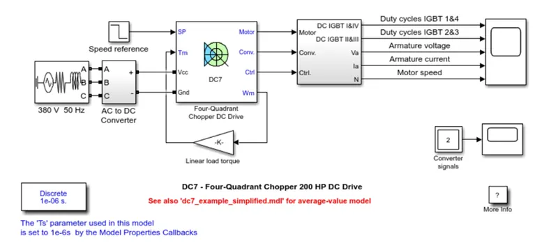
in this model we changed the input ac current source with the battery which is located in the library at Simscape / Electrical / Specialized Power Systems / Electric Drives / Extra Sources.
Also, we added the scope to the speed reference to observe the input vlue of the step speed reference.
In the four-quadrant chopper DC Drive the DC Motor that we used with the rating of 5 HP, 240 V, 1750 RPM, with the field voltage of 300 V.
After all the modifications in the DC7 the new model will look like as shown below,
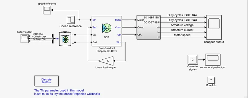
After checking all the connections of the blocks, we can run the model by taking the stop time with 10 sec. after this the output values from the different scopes are,
The input of the speed reference is look like as shown,
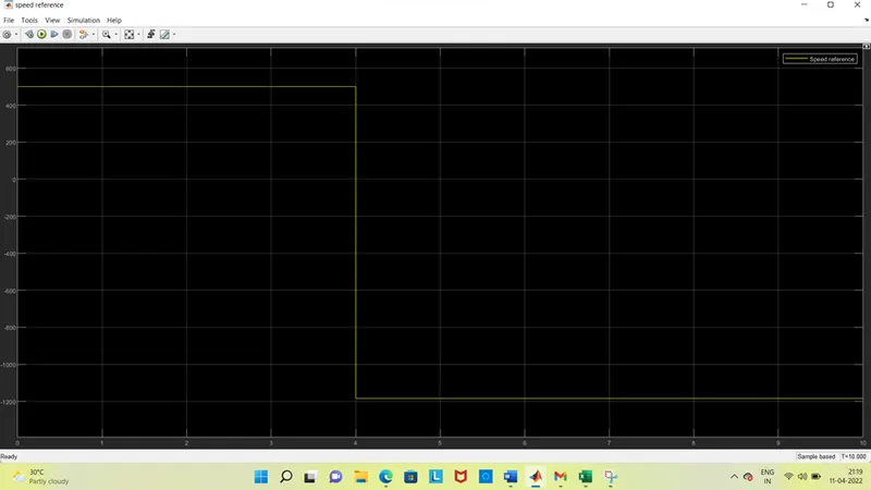
Here as the input given at the speed reference by the step signal block the input look like as above. Here at start the input is given as the value from 500 rpm from 0 to 4 sec, at the time 4 sec the value of the speed reference changed to negative with the value 1184 from 4 to 10 sec.
the output values of the Simulink model are,
Battery output:
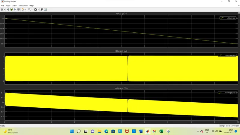
In this battery output graph, we can get the values of state of charge (SOC), current in Amps, Voltage in Volts as above.
From the SOC we can observe that the value is decreased slightly from 100% to 99.89%. this we can say that the energy utilized by the chopper from the battery.
If we observe the second one which is the current value In Amps which is flows in between 2A to -2A and it changes at the point 5.27 sec but the values are in the same position at 2A to -2A only.
From the third graph that is voltage which is measured in volts is changes as the SOC that is slightly from 8.44V to 8.335V here also the voltage values are changed that is switched at the point 5.27 sec and after changing the values the value reduced continuously up to 8.335V to 10 sec.
If we observe both the values of current and voltage which flows In the direction opposite each other from start to end.
Converter signal output:
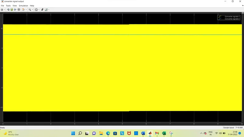
The converter signal output the four-quadrant is as below,
In this converter signal the values changes from 11 to -11, which is the signal 1. The converter signal 2 is in constant with the value of 8.41
Chopper output:
The chopper output has the 5 outputs named as,
IGBT 1, 2, 3 & 4 duty cycles.
Armature voltage (V)
Armature current (A)
Motor speed (rpm)
The output of this chopper looks like.
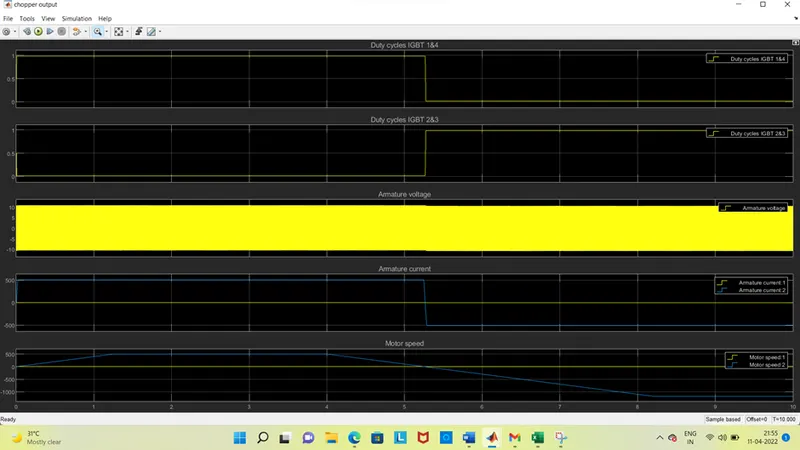
In the first graph which is the duty cycle of IGBT 1&4. On this the value is 1 from the time 0 to 5.27 sec due to the switching command which is used to convert from the current of fixed DC to variable DC.
The IGBT 2 & 3 also changes at the point 5.27 sec from the 0 to 1 which is designed by the chopper. But due to some inductance nature at the switch it takes time some time to change the value from o to 1 and 1 to 0 respectively.
In the third graph we can observe the armature voltage which is varies from 11V to -11V and due to change in the IGBT switching its voltage direction also changes but it varies in the same values in the same plane. If we observe that it looks similar to the converter signals.
As the same the current also varies from the range between 500 to -500 Amps which is due to changes in the IGBT 1&4 and 2&3 respectively. Here if we observe that the armature current is constant at the total running time with the value of 0 but the armature current varies from 500A to -500A at the point 5.27 sec. here also due to some inductance nature the current takes time to change the direction.
If we observe the speed that is motor speed1 which is from 0 to 500 rpm which increased with some delay and also takes time to reach 0 at 5.27 sec after that due to change the direction of current in the circuit the speed changes to reverse that, is it rotates in the reverse direction with the speed of 1184 rpm at negative side. if we observe here that it takes more to reach the speed at reverse direction due to high speed and after reaches the max speed value it remains constant up to the given time.
Table for assumed parameters:
|
parameters |
Values |
|
Mass of the towing vehicle |
9,000 Kg |
|
Mass of the air craft |
84,000 Kg |
|
Length of the aircraft |
11.6 m |
|
Height of the aircraft |
7.45m |
|
Coefficient of the rolling resistance (Crr) |
0.013 |
|
Drag coefficient (Cd) |
0.75 |
|
Air density (ρ) |
1.225 Kg/m3 |
|
Speed of the truck |
25 Kmph or 6.9445 m/sec |
|
Taxing or travelled time |
15 minutes |
|
Battery voltage |
40 V (6 no’s) |
|
Motor power |
210 Kw |
|
Motor Terminal voltage |
240V |
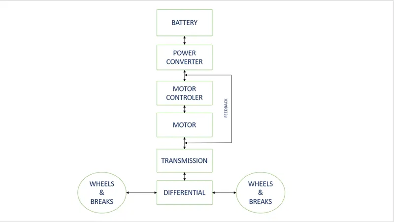
Block diagram of power train:
B. Designing the parameters in excel sheet.