Week -2
- Make a Simulink model of Doorbell using solenoid block with the
Create a situation where the switch is closed for 2 seconds and then released. Observe the physical movement of the plunger.
Make a Simulink model of doorbell using solenoid block
Making a mathematical model of doorbell by using solenoid by Simulink be like as below fig 1.
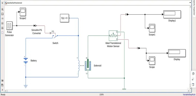
Fig 1.
In the above arrangement, when the switch is closed the electromagnet receives electrical power from the battery and pulls the metal arm to hit the bell producing sound. Here the generally used blocks to make the mathematical model of doorbell using solenoid are.
Blocks used;
Pulse generator
Simulink-ps converter
Ps – Simulink converter
Switch
Battery
Electrical reference
Solver configuration
Solenoid
Ideal translational motion sensor
Mechanical reference
Display
Scope
In the above diagram
Green colour represents – Mechanical systems
Blue colour represents – Electrical systems
Black colour represents – Simulink systems
Procedure;
As per given condition of closing of switch for 2 sec .and then release, here we using the pulse generator by changing some changes as shown in fig2.
By these changes the input can be look as shown in fig 3.
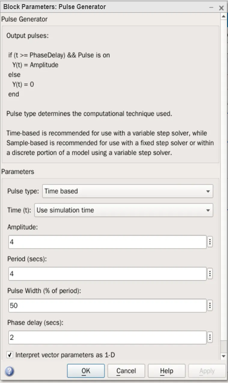
fig2.
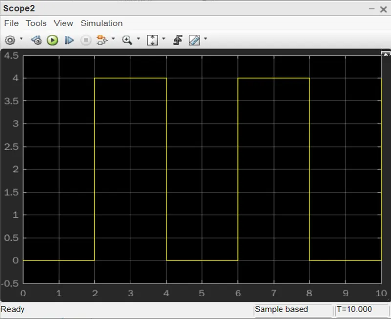
Fig 3.
This pulse generator is connected to the switch which is as the signal input.
The Simulink -ps converter is used to convert between the pulse generator and switch. Here if the external physical signal ps is greater than the threshold, then the switch is closed, otherwise the switch is open.
Solenoid is used to pull the metal arm which is used to hit the bell to ring the alarm. The supply is provided via batteries. Batteries are connected in series to the solenoid. the electrical reference is used as a reference which is used as earth. The solver configuration is used to connect to the electrical systems which is used to connect the solver settings to use for simulation.
Ideal translational motion sensor is a mechanical system which is used to measures velocity or displacement in a mechanical translational network. here it is used to sense(identify) the motion or movement of the solenoid based on the electrical inputs in the system.
The scope block is used for the graphical representation of the input signal from the pulse generator, and the output from the ideal translational motion sensor respectively.
Display is used to see the output of the model.
When we run the model with this configuration, we will get the results as shown in below figs. from the ideal translational motion sensor the graphical representation is collected from the physical signal ports v and p report the velocity and position, respectively.
Graphical representation of velocity is shown in fig 4.
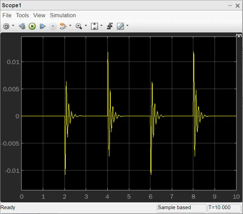
Fig 4.
Hence by using the given condition we completed the mathematical model of doorbell using solenoid.
Use a thermistor to sense the temperature of a heater & turn on or turn off the fan as per the below conditions:
Temperature source: 20 °C from 0 to 10 seconds, 27 °C from 10 to 30 seconds, 23 °C from 30 to 50 seconds.
Fan conditions: ON if the temperature above 25 °C, OFF otherwise.
By using this conditions we design the model as shown in the given below fig 5.
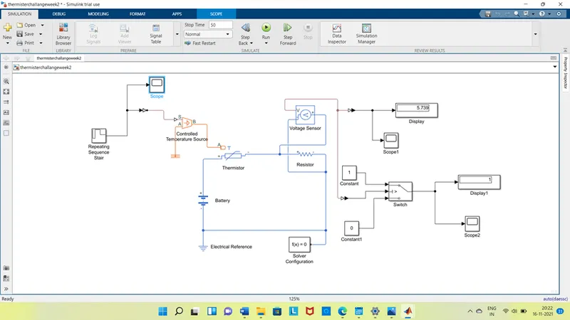
Fig 5.
As shown above we use the blocks for the thermistor control model are.
Blocks used;
Repeating sequence stair
Ps – Simulink converter
Simulink – ps converter
Controlled temperature source
Thermistor
Resister
Voltage sensor
Switch
Solver configuration
Electrical reference
Thermal reference
Scope
Display
Procedure;
The first block used to create a thermistor to sense temperature of a heater is thermistor, it is advice which is measures temperature of a resister. It works based on relation between resistance and temperature, here we used block in Simulink for thermistor is positive temperature co-efficient thermistor. It increases or decrease resistance based on the temperature changes respectively, it is controlled by controlled temperature source, which takes the signal as input and control the thermistor based on the signal. The mechanical reference is been given as reference to the controlled temperature source.
To produce the signal in the model we use signal builder is the repeating sequence stair, by this block we can change the sequence of pulse repeatedly. As shown in the given fig 6. Based on the given conditions
Time = 0 to 10 sec & temperature = 293k.
Time = 10 to 30 sec & temperature = 300k.
Time = 30 to 50 sec & temperature = 296k.
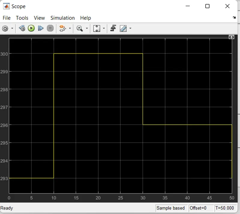
Fig 6.
The scope is used to see the graphical representation of the given input signal.
Simulink – ps converter is used to convert the Simulink systems to the ps systems.
Resister is used as the heater reference whish be sensed by the thermistor.
Battery is connected in series with the thermistor and resister respectively.
Voltage senser is connected to the resister to identify the output of the resister which is given as in put through repeating sequence stair. The output of the voltage sensor is displayed through display block and graphical representation through the scope blocks respectively.
Switch is used to control the fan to turn on if the temperature reaches 298k (25 °C) or above, off otherwise. The switch is connected to the voltage sensor signal to compare the two input ports constant blocks which is used to display based on the threshold value of the signal. Its output can be observed in display and scope as output values and graphical representation respectively.
The solver configuration is used to solve the model-based parameters to run the simulation.
The electrical reference is used to refer as a earth to the electrical systems. The outputs of the voltage sensor and the switch is shown below fig 7.and fig 8.
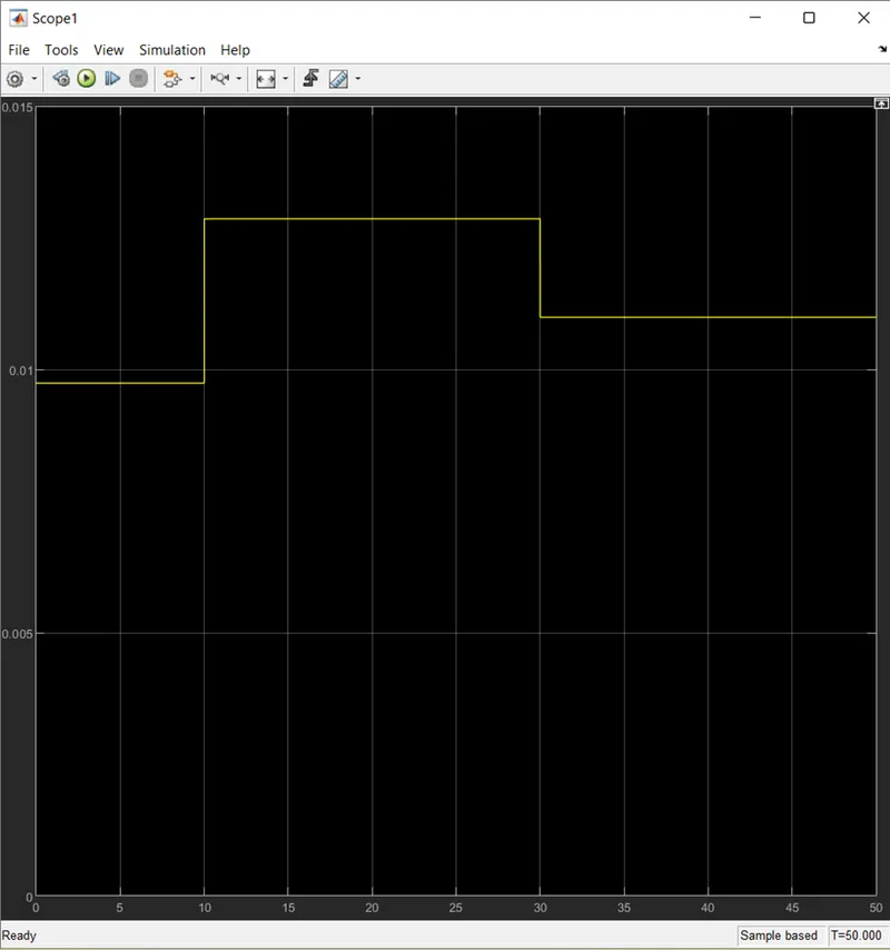
Fig 7.
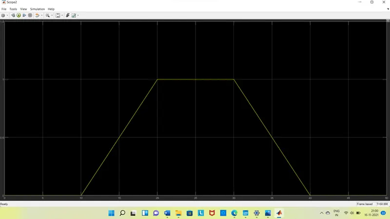
Fig 8.
By this graph we can conclude that the fan is off from 0 to 10 sec because the temperature is 293k which is below 298k, after that 10 to 30 sec it reaches 300 hence fan is on, after that 30 to 50 sec fan goes to off condition because it reaches to 296kwhich is less than 298k.
Hence by using the given condition we completed the mathematical model of a thermistor to sense the temperature of a heater & turn on or turn off the fan