Week-6 Challenge: EV Drivetrain
- Which types of power converter circuits are employed in electric and hybrid electric vehicle?
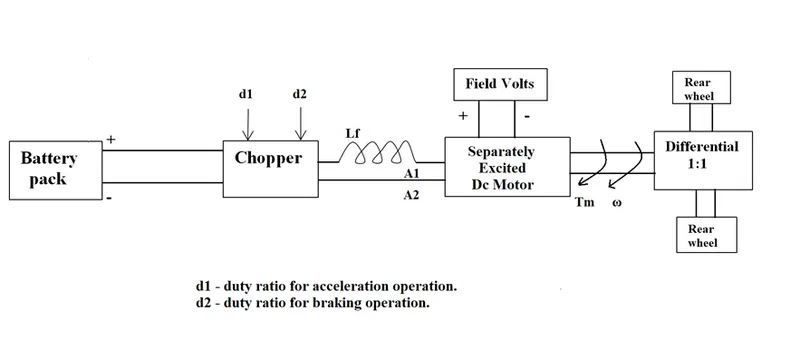
- An Electric Vehicle's powertrain with 72V battery pack in shown in the diagram below. The duty ratio for acceleration operation is 'd1' and for the braking operation the duty ratio is 'd2'.
The other parameters of the electric vehicle is given below,
Motor and Controller Parameters:
Rated Armature voltage= 72 V
Rated armature current= 400 A
Ra= 0.5Ω, KΦ= 0.7 Volt second
Chopper Switching frequency= 400 Hz
The vehicle speed-torque characteristics are given by the below equation

What is EV steady state speed if duty cycle is 70%?
- Develop a mathematical model of a DC Motor for the below equation using Simulink.
ω= V/K.ϕ -Ra/Kϕ^2. T
Refer to the blog on below topic:
Induction Versus DC brushless motors by Wally Rippel, Tesla
Explain in brief about author’s perspective.
Aim:
- To get to know the types of converters used in HEV or EV vehicles.
- To find the speed using torque-speed relation.
- To get to know about induction and dc brush less motors.
Objective:
- To get information on converters for HEV and EV vehicles.
- Find the speed using torque-speed expression.
- Try to find the best options for motors for HEV or EV vehicles.
- Which types of power converter circuits are employed in electric and hybrid electric vehicle?
A motor drive consists of a power converter and the controller. The power converters are electrical and electronic circuits that are used either connect DC to AC and vice versa. These power electronic converter handles the flow of bulk power from the source to the motor input terminals. The controller processes the command input and get the feedback information to generate the switching signals for power converter semiconductor switches. It is used in EV and HEV to manipulate the currents and voltages and to fed based on the vehicle needs.
The power converter is made of high-power fast-acting semiconductors devices, such as bipolar junction transistor. These are some other transistors such as MOSFET, IGBT, SCR, GTO, MCT. These devices are used as on-off electronics switch to convert the fixed supply voltage and variable frequency supply.
All these devices have a control input gate or base through which the devices are turned on and off as per the command generated by the controller.
There are two types of step converters. When a low voltage input is converted into a high voltage output it is a step-up converter. Whereas a high voltage input id converted into a low voltage output it isa step down converter.
The power converter can be a DC drive supplying a DC motor or an AC drive supplying an AC motor.
The power converter types used in the EV and HEV are given below those are:
- DC to DC converter
- AC to AC converter
- AC to DC converter (rectifier)
- DC to AC converter (inverter)
- DC to DC converter:
A DC/DC motor converter in its basic form converts unregulated DC input voltage at a certain level to regulated DC output voltage at a different level with very high conversion efficiency. These are operated at very high frequency. The switches are turned ON and OFF by pulse width modulation (PWM).
It provides low voltage (12v to 14v) for low voltage loads.
- AC to AC converter:
An AC / AC motor converter in its basic form converts unregulated AC input voltage at a certain level to regulated AC output voltage at a different level. The above converters either increase the magnitude of the output voltage (boost converters) or reduce the output voltage (buck converter). The output voltage is controlled by varying firing angle of TRIAC. These types of converters are known as AC voltage regulators.
- AC to DC converter:
AC to DC converters is one of the most important in power electronics because there are lot of real applications are based on these conversions. The AC to DC conversion process is know as rectification. The rectifier converters ac supply into the DC supply at load end connection. Normally transformers are used to adjust the AC source to get step down transformer to reduce the voltage level to have better operation range for DC supply. AC supply is converted in to 12v or 48v DC supply. an AC to DC converter will prevent the current changing direction, so that it only flows unidirectionally. In the circuit, there is a step-down transformer, a diode, capacitor and a low dropout voltage regulator. A diode or group of diodes is implemented to restrict the current to flow in just one direction. In AC wawe form, there will be positive and negative half cycles. The diode or diodes will eliminate or remove the negative peaks so that only positive half cycles woukd be present as output. This process is called ‘rectification’.
Rectifiers can be classified as:
- half-wave and full-wave rectifier.
- Controlled and uncontrolled rectifier.
- Centre-tapped and bridge rectifier.
- DC to AC converter:
A DC to AC converter or an invetrter is a device that converts DC power from the battery to AC power used in an electric vehicle motor. The inverter can change the speed at which the motor rotates by adjusting the frequency of the alternating current. The use of the inverters can increase or decrease the power or torque of the motor by adjusting the amplitude of the signal. It plays a significant role in capturing energy from regenerative breaking and feeding it back to the battery. The output waveform of ideal inverters should be sinusoidal. However, the waveform of practical inverters are non-sinusoidal and contain certain harmonics.
Usage of converters:
Mainly the converters are used in,
- AC to DC converter (rectifier) used in EV charger.
- DC to DC converter (chopper) used in supply DC power to auxiliary like radio and car headlights and indicators etc.
- DC to AC converter (inverter) used in the supply power to motor.
- An Electric Vehicle's powertrain with 72V battery pack in shown in the diagram below. The duty ratio for acceleration operation is 'd1' and for the braking operation the duty ratio is 'd2'.
The other parameters of the electric vehicle is given below,
Motor and controller Parameters:
Rated Armature voltage = 72 V
Rated armature current = 400 A
Ra=0.5Ω, KΦ=0.7 Volt second
Chopper Switching frequency = 400 Hz
The vehicle speed-torque characteristics are given by the below equation.
What is EV steady state speed if duty cycle is 70%?
Given:
Rated armature current (A) = 400 A
Rated armature voltage (V) = 72 V
Armature resistance (Ra) = 0.5 Ω
KΦ=0.7 Volt second
Switching frequency = 400 Hz
Duty cycle (dc) = 70% = 0.7
The average voltage is given by the product of the battery voltage and the duty cycle, i.e.
`Vs=V ×dc`
`V( s)=72×0.7`
Vs = 50.4
Therefore, the average voltage is 50.4V.
The vehicle speed-torque characteristics are given by the below equation.
The derived formula for the motor speed characteristics is,
`T= (V_s ×k∅)/Ra- ((k∅)^2×ω)/R`
By substituting the values, we get,
`T= (50.4 ×0.7)/0.5- (0.7^2×ω)/0.5`
`T=70.56-0.98 .ω`
By comparing these two we get,
`70.56-0.98 .ω= 24.7+( 0.0051).ω^2`
`0.0051.ω^2+0.98.ω-45.86=0`
By using the quadratic equation formula, we get speed (`ω`)
`ω= -b±√(b^2-4.a.c)/2a`
`ω=-0.98±√(0.98^2-(4.0.0051.(-45.86)))/(2×0.0051)`
`ω= -0.98±1.377/0.0102`
We get two solutions for this angular speed.as
`ω=38.92 rad/sec`& `ω=-231.07rad/sec`
We can consider only the positive value,
Angular speed = 38.92 rad/sec.
- Develop a mathematical model of a DC Motor for the below equation using Simulink.
ω= V/K.ϕ -Ra/Kϕ^2. T
based on the given equation we can plot the model as below.
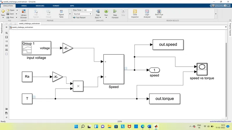
As we ca see that for input voltage, we use the signal builder as input.
For torque value T and resister Ra we use constant blocks, and for constant 1/K.ϕ and its square value we used a gain block because of its denominal function.
For the summation and subtract uses add block as the same for multiplicand Ra/Kϕ^2 and T we use product block.
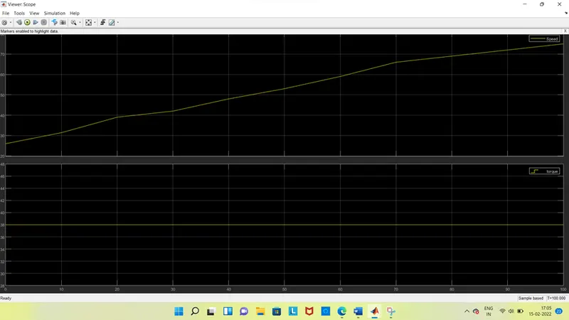
For the output we used the scope which shows the value at each sec.
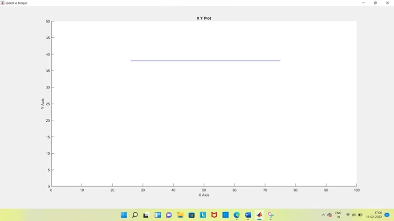
For speed torque characteristics we used the xy graph.
Here we used the to workspace blocks which is connected to the xy graph, because we can’t connect the speed and torque values directly to it.
After running the model, we get the results as,
At speed and torque scope.
At xy graph.
4.Refer to the blog on below topic:
Induction Versus DC brushless motors by Wally Rippel, Tesla
Explain in brief about author’s perspective.
According to the blog ‘induction vs DC Brushless motors by Wally Rippel, Telsa’, the writer states the changes in the world years ago and the latest technological trends that are happening. He then explains about the DC Brushless motors and induction motors.
DC Brushless Machines:
According to him the rotor has two or more permanent magnets that generate a DC magnetic field. This magnetic field will enter the stator core which interacts with the currents flowing in the windings to produce an interaction between rotor ad stator. It needs a proper flow of current into the rotor and stator if it’s not connected properly then the current will not generate and the torque decreases and if it vary constantly it reaches to zero. During the electric and mechanical conversion when the rotor is rotating, the magnitude and polarity of the stator current will continuously vary such that the torque remains constant and optimal efficiency is achieved.
In an ideal brushless drive, the strength of the magnetic field produced by the permanent magnets would be adjustable. When maximum torque is required, especially at low speeds, the magnetic field strength (B) should be maximum – so that inverter and motor currents are maintained at their lowest possible values.
This minimizes the I² R losses and thereby optimizes efficiency.
Induction Motor:
The 3-phase induction motor was invented by Nikola Tesla sometime before 1889. The stators for the 3-phase induction motor and the DC brushless rotor are seems like same at the looks and operation. Both have three sets of distributed windings that are inserted within the stator core. The essential difference between the two machines is with the rotor.
Unlike the DC brushless rotor, the induction rotor has no magnets. They have just stacked steel laminations with buried peripheral conductors that form a ‘shorted structure’. Currents flowing in the stator windings produce a rotating magnetic field that enters the rotor. The frequency of this magnetic field as seen by the rotor is equal to the difference between the applied electrical frequency and the rotational frequency of the rotor itself.as the same An induced voltage exists across the shorted structure that is proportionate to this speed difference between the rotor and electrical frequency. The currents are produced within the rotor conductors that are approximately proportionate to the voltage, hence there’s a speed difference. Finally, these currents interact with the original magnetic field to produce force.
When a 3-phase induction motor is connected to utility type 3- phase power, torque is produced at the outset. The motor has the ability to star under load. No inverter is needed. The fact that induction motors are directly compatible with conventional utility power is the main reason for their success. In contrast, a brushless DC motor produces no starting torque when directly connected to fixed frequency utility power. They really need the aid of an inverter whose phase is maintained in step with the angular position of the rotor.
Differences:
According to wally rippel both DC brushless and induction drives use motors having similar stators. Both drives use 3-phase modulating inverters. The only differences are the rotors and the inverter controls. And with digital controllers differences are with control code.
The DC brushless requires a position sensor but an induction motor requires only a speed sensor.
Less rotor heat is generated in DC brushless drive and rotor cooling is easier and peak point efficiency is generally higher.
DC brushless drive operates at a power factor of one, whereas the induction drive power factor is 85%.
With the increase in the size of the DC brushless machine, magnetic losses increase and the part-load efficiency decreases, whereas the induction drives, as the machine size increases, losses don’t grow. During high-performance tasks, induction drives are suitable.
He then explained that there were only a few brushless drives in the past but now most of the hybrid electric vehicles use it.
Finally, we can say based on the writer view that the DC brushless will dominate the Hybris Electric Vehicles Markets but the induction drive will maintain dominance in the hybris performance in the pure electric vehicles. As of now, there is no winner out of the two as each has its advantages and disadvantages, by changing of these we can get the good performance structure.