Project-1: Powertrain for aircraft in runways
Part A:
1.Search and list out the total weight of various types of aircrafts.
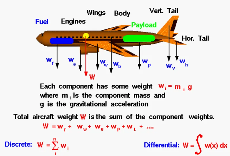
Weight is the force generated by the gravitational attraction of the earth on the airplane. Each part of the aircraft has a unique weight and mass, and for some problems it is important to know the distribution. But for total aircraft maneuvering, we only need to be concerned with the total weight and the location of the center of gravity. The center of gravity is the average location of the mass of any object.
The total weight W of the aircraft is simply the sum of the weight of all of the individual components.
W = w(fuselage) + w(wing) + w(engines) + w(payload) + w(fuel) + ...
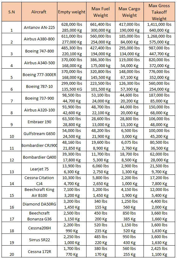
The table below shows the weight of the different types of aircraft:
2.Is there any difference between ground speed and air speed?
Ground speed: It is the horizontal speed of an aircraft relative to the ground. An aircraft heading vertically would have a ground speed of zero. Ground speed can be determined by the vector sum of the aircraft's true airspeed and the wind speed and the direction of motion.
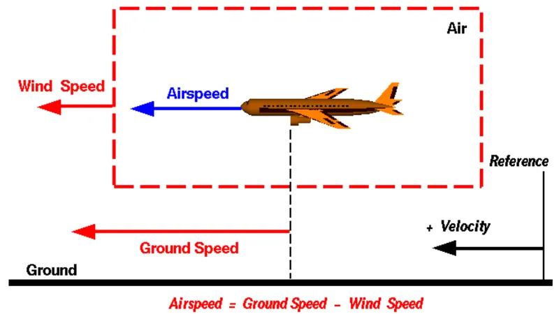
Wind speed: If we pick a reference point on the ground, the air moves relative to the reference point at the wind speed. A positive velocity is defined in the direction of the aircraft's motion.
Airspeed: The important part in the generation of the lift of aircraft is the relative velocity between the object and the air, which is called airspeed. It can not be directly measured from the ground position. It is computed from the ground speed and the wind speed. It is the vector difference between the ground speed and and the wind speed.
The airspeed is then given by:
Airspeed = Ground Speed - Wind Speed
Aircraft usually operates on the gound as well as in the air, so ground speed and air speed usually change based on the wind component. If we consider that there is no wind component, then ground speed is equal to the airspeed. If the wind is blowing in the tail direction of the aircraft then airspeed is greater than wind speed (air speed = ground speed + wind speed). If the wind is blowing in the head direction of the aircraft then airspeed is less than ground speed (air speed = ground speed - wind speed). Gravity also plays a major role in increasing the aircraft speed while its descending. If the measure airspeed is greater than observed ground speed then the wind speed becomes positive. Here wind speed is the vector difference between ground and air speed. If in case the wind is zero it is equal to ground speed.
3. Why is it not recommended to use aircraft engine power to move it on the ground at Airport?
The engine of the aircraft can easily do the work under its low power to go towards runways and after landing taxi to their assigned gate. But as we know that the engine is so powerful that the thrust developed produces jet blast which might cause damage to the terminal building or various people and equipment. Engines which are close to the ground may also blow sand and debris back and forth which may get sucked to the engine. A pushback is therefore the preferred method to move the air craft away from the gate and most importantly it reduces the cost of aviation fuel. Taxing can save a lot of money.
- There is a risk of injury to ground support personnel who may be in relatively close to the air craft.
- It is easier for the truck driver to see the surroundings better than the pilot who is sitting in the cock-pit with limiting window, the pushback driver knows the airport better than the pilot.
- Effectively a loss of control can happen, especially during high power engine running. Damage can occur to the aircraft itself, other aircraft nearby and other buildings.
- A new system was proposed where a new system in which a push-back truck will move the aircraft all the way to run-way to save fuel and reduces impact of environment.
- The plane engines are very loud, when more than one plane will addup their sound, then it will be unbearable for passengers and other parts near airport.
4. How an aircraft is pushed to runway when its ready to take off?
Push Back:
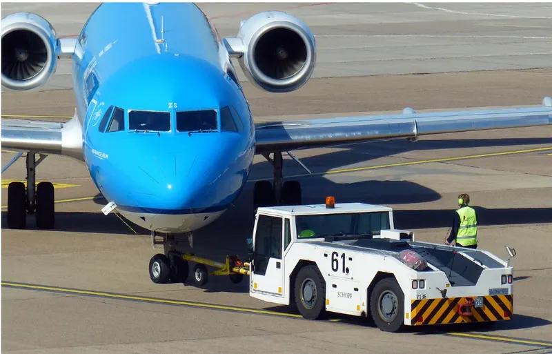
- In aviation, pushback is an airport procedure during which an aircraft is pushed backwards away from an airport gate by external power. Pushback are carried out by special, low profile vehicles called pushback tractors or tugs.
- Pushback at busy aerodromes are usually subject to ground control clearance to facilitate ground movement on taxiways. Once clearance is obtained, the pilot will communicate with the tractor driver to start the pushback. To communicate, a headset may be connected near the nose gear.
- Since the pilots can not see what is behind the aircraft, steering is done by the pushback tractor driver and not by the pilots. Depending on the aircraft type and airline procedure, a bypass pin may be temporarily installed into the nose gear to disconnect it from the aircraft's normal steering mechanism.
- Once the pushback is completed, the towbar is disconnected and any bypass pin is removed. The ground handler will show the bypass pin to the pilots to make it clear that it has been removed. The pushback is then completed and the aircraft can taxi forward under its own power.
Taxing:
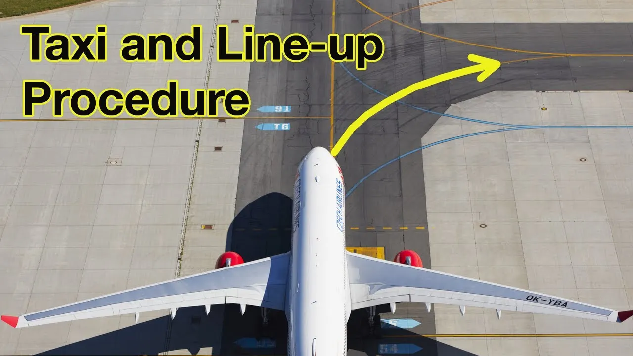
- Taxing refers to the movement of an aircraft on the gound under its own power. The aircraft moves on wheels. An airplane uses taxiwaya to taxi from one place on an airport to another. For an example, when moving from a terminal to the runway.
- The aircraft always moves on the ground following the yellow line, to avoid any collision with the surrounding buildings, vehicles or another aircrafts. The taxing motion has the speed limit. Before making a turn, the pilot reduces the speed further to prevent tire skids. Just like cars, there is a certain list of priorities during taxing. The aircrafts that are landing or taking off have higher priority. The other aircrafts have to wait for these aircrafts before they start or continnue taxing.
- The thrust to propel the aircraft forward comes from its propellers or jet engines. Steering is achieved by turning a nose wheel or tail wheel/rudder; the pilot controlling the direction travelled with their feet. The use of engine thrust near terminals is restricted due to the possibility of jet blast damage. This is why the aircrafts are pushed back from the buildings by a vehicle before they can start their own engines for taxiing.
5. Learn about take off power, tyre design, rolling resistance, tyre pressure, brake forces when landing
Take off power:
- Take off power is the phase of flight in which an aerospace vehicle leaves the ground and becomes airborne on take-off, in order to position the aircraft to a safe height away from terrain and obstacles. The engine thrust is set to a high take-off power setting and the aircraft altitude is pitched up by to maintain a specific speed by fulfilling the task is known as the take off power.
- Take off performance can be predicted using a simple measure of the acceleration of the aircraft along the runway based on force equilibrium
The forces involved will be:
T = thrust of propulsion system pushing aircraft along runway
D = Aerodynamic drag of vehicle resisting the aircraft motion
F = Rolling resistance frictiondue to the contact of wheels or skids on the ground
During take off run the imbalance in these forces will produce an acceleration along the runway.
`(dv)/(dt) = (T-D-F)/m`
where, `(dv)/(dt) =`acceleration along the runway
m = mass of the vehicle
whereas,
Power = (T - D - F)*V
Tyre Design:
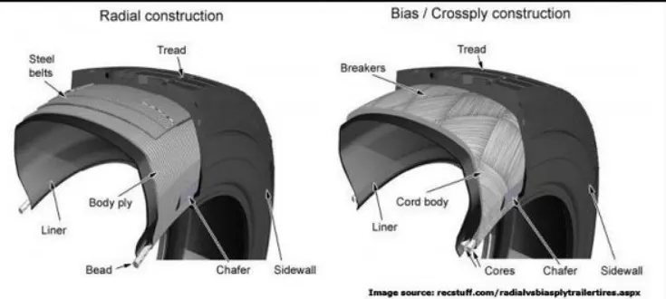
- An aircraft tyre is design to withstand extrremely heavy loads for short durations. The number of tires required for aircraft increases with the weight of the aircraft, as the weight of the airplane needs to be distrubuted more evenly. Aircraft tire tread patterns are designed to facilitate stability in high crosswind conditions, to channel water away to prevent hydroplaning, and for braking effect.
- A tyre is made from rubberized fabric piles over a rubber liner and the edges of the piles are wrapped around a wire bead, which holds the tyre to the wheel rim. The fabric piles are covered with a rubber compound for the side walls. The tyre is cured in a mould to vulcanize the parts into a single unit and form the tread design.
- Unlike an automobile or truck tyre, it does not have to carry a load for a long period of continuous operation. However an aircraft tyre absorbs the high impact loads of landing and also it is operating at high speed for a short time when required.
- Aircraft tyre may be Radial or Bias - Almost all airlines are using Radial tyre. Bias is an older design and it is mainly used for road vehicles. Radial tyres have the word RADIAL on the sidewall. Radial tyres are more expensive that the bias-ply tires. Radial tyres are in demand because of their lower life cycle cost and long term value.
Rolling Resistance:
The rolling resistance or rolling friction is a force that resists the motion of a body that rolls on a surface. In the case of aircraft, the rolling force exists between the aircraft tyres and the runway surface it rolls upon. For a given body, its rolling resistance is mathematically expressed as the product of the coefficient of the rolling resistance and the normal force, which is the force that is acting perpendicularly to the surface on which rolling action occurs.
Frr = `mu`rr * N
where,
Rolling resistance Force = Frr
Coefficient of rolling resistance = `mu`
Normal force = N
The above expression for the rolling resistance can only be considered when there are no other vertical forces acting on the rolling body. However during take-off, we must consider the effect of the lift force as well. In this case, the normal force would be equal to the difference between the weight of the aircraft acting on the tire and the lift force acting on the wheel. This can be written mathematically as:
Frr = `mu`rr * (W - L)
In general, a standard termac runway is considered to have a coefficient of rolling resistance of 0.02.
Tyre pressure:
- Aircraft tyre are inflated with an inert gas and the most commonly used is Nitrogen. Inert gases are used for inflation because they are non-reactive and not flammable.
- Aircraft tyres operated at such high extreme of pressure, load and speed. Their care and service are critically important. The most important action an operator can take to prevent tire related events is to maintain proper tire inflation pressure.
- Aircraft tyres are usually inflated with nitrogen to minimize expansion and contraction from extreme changes in ambient temperature and pressure experienced during flight. Dry nitrogen expands at the same rate as other dry atmospheric gases, but common compression air source may contain moisture which increase the expansion rate with temperature.
- Aircraft tyres generally operate at high pressure upto 200 psi (14 bar or 140 KPa) for airlines and even higher for business jets.
- The main landing gear on the concorde was typically inflated 232 psi (16.0bar) While its tail bumper gear tires were as high as 294 psi (20.3 bar).
- Test of airline aircraft tire have shown that they are able to sustain pressure of maximum 800 psi (55 bar : 5,500 KPa) before bursting. During the test the tires have to be filled with water, to prevent the test room being blown apart by the energy that would be released by a gas when the tire burst.
Brake forces when landing:
- All the commercial aircraft have automatic brake systems, just like a car. These system also have Anti-Lock braking system that prevents the tires from sliding down a wet runway.
- The advantage of the automatic brake system is that the aircraft brake comfortably at a constant decceleration. Passengers experience a constant force that presses them into their seats.
- The brake system automatically applies the wheel brakes just enough to create a constant decceleration independent of the air resistance, spoilers and reversers. It is only in the last phase of brakes by pressing on both brake pedal. This deactivates the automatic brake system. Immediately after landing, the aircraft is still moving fast enough that aerodynamic devices are much more efficient.
- The brakes units are powered by the hydraulic system. An electrical signal is send from the flight deck to hydraulic actuators near the main landing gear. Here hydraulic fluid at 3,000 pound per square inch is used to force the brake unit against the wheel, thus slowing it down.
Part B:
6.
A. With necessary assumptions, calculate the force and power required to push / pull an aircraft by a towing vehicle.
Answer:
Assumptions:
- The runway is the flat surface so the hill climbing force is zero.
- The vehicle is running at a very low speed so the aerodynamic force is very low.
- The speed of the vehicle is very low so the acceleration force is neglected.
- The forces acting on the vehicle are rolling resistance force and the aerodynamic force.
First we have to calculate the Tractive force required to pull out the aircraft.
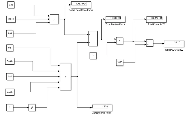
So the tractive force is given by sum of the rolling resistance force and the aerodynamic force as:
Fte = Frr + Fad
Where,
Fte = Tractive force
Frr = Rolling resistance force
Fad = Aerodynamic force
The rolling resistance force is given by:
Frr = `mu`rr * m * g
Where,
Frr = rolling resistance force
`mu`rr = Coefficient of rolling resistance
g = Gravitation force acting on the vehicle
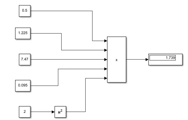
Fad = `1/2 * rho * A * Cd * V^2`
Where,
Fad = Aerodynamic force
`rho` = Air density
A = Frontal area
Cd = Coefficient of drag
V = velocity of the vehicle
Here I consider the Eagle Electric ETT-16 model.
Reference link: https://eagletugs.com/aircraft-tugs/eagle-tt-electric-aircraft-tugs-ett-16
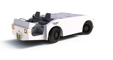
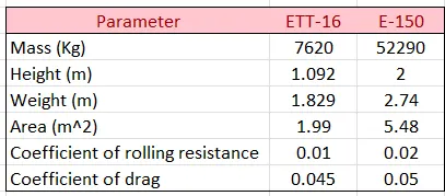
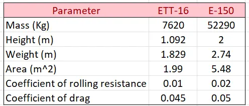
Mass of the vehicle = 7,620 kgs
Height = 1,092 mm
Width = 1,829 mm
Frontal Area = 1.99 m^2
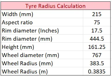
Tyre specification = 215/75 R17.5 LR F
Aircraft is Embraer E-jet consider.
Reference link: https://en.wikipedia.org/wiki/Embraer_E-Jet_family
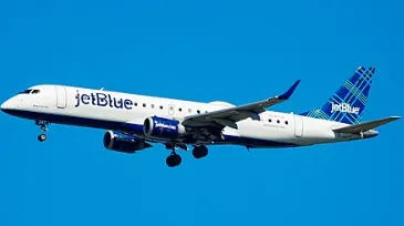
Weight = 52,290 kg
Height = 2 m
Width = 2.74 m
Frontal Area = 5.48 m^2
Tyre specification = 42/16 R20
The total specification is given below in the table:
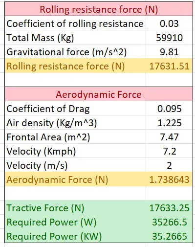
The total tractive force and the power is calculated in the below table:
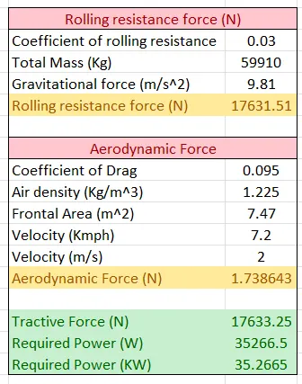
So the total power required to push/pull an aircraft with the towing vehicle is 35.27 KW.
B. Develop the model for the calculated force and power using Simulink.
Answer:
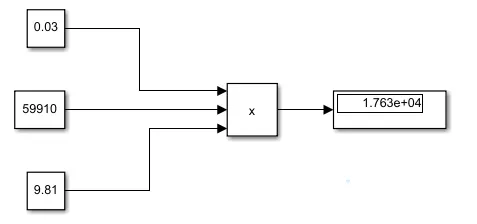
Mathematical model of rolling resistance force:
Mathematical model of aerodynamic force:
Mathematical model of the Total Force and Power required by the vehicle to push/pull the aircraft:
7.
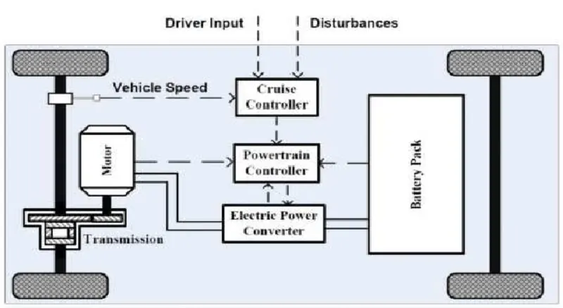
A. Design an electric powertrain with type of motor, it’s power rating, and energy requirement to fulfill aircraft towing application in Simulink. Estimate the duty cycle range to control the aircraft speed from zero to highest. Make all required assumptions. Prepare a table of assumed parameters. Draw a block diagram of powertrain.
(Hint :DC7 Block)
Answer:
Block diagram of the electric vehicle powertrain:
Now to calculte the Motor Rating:
- From the simulink model of the total power required to push/pull the aircraft, it is seen that the power required is 35.27 KW.
- It is the total mechanical power required by the motor to push forward the towing vehicle.
- We have to calculate the electric motor rating considering the losses in the machine.
- So by considering the 95 % efficiency, the rating of the machine is calculated by the below formula.
Efficiency, `eta` = Pout/Pin
`0.95 = 35.27/Pin
So Pin = 37.12 KW (Peak)
So the motor rating of the 37.3 KW (i.e 50 HP) is selected for the given towing vehicle.
Now to calculate rating of the DC-DC converter:
- The motor rating is 37.3 KW so we have to design the DC-DC converter to supply the electrical power of 37.3 KW to the motor.
- Now considering the efficiency of the converter as 95 %.
- So the input power is calculated as 39.24 KW.
Now to calculate rating of Battery:
- The output required from the battery is 39.24 KW.
- Taking the total time of travel as 120 sec.
- The energy required by the battery is calculated as:
Energy = `(39.24*120)/3600`
Energy = 1.308 KWhr
- Now the Ampere-hour capacity of the battery is
Q = Energy/Voltage
Q = `(1.308*1000)/120`
Q = 10.9Ahr
Simulink Model of the Powertrain:
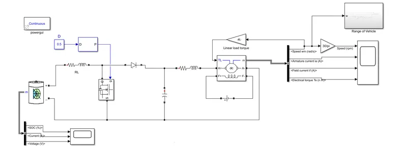
- In the above simulink model of the powertrain, the range of the vehicle is calculated.
- Battery source of 10.9 Ahr is used to supply the energy.
- The DC-DC boost converter is used which gives the output voltage of 240 for the DC motor.
- The field of the DC motor is excited by the DC voltage source of 300 V.
Mathematical model of Range of vehicle calculation:
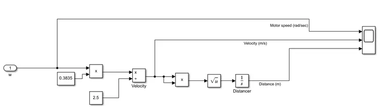
- Here the range of the vehicle is calculated by taking input as the angular speed of the vehicle.
- The velocity of the vehicle is calculated by the angular speed of the vehicle by using below formula:
`w = G*V/r`
- The radius of the wheel of the vehicle is calculated as 0.3835 m
- And the gear ratio is taken as 2.5.
- The distance travelled by the vehicle is calculated by taking the integration of the vehicle speed.
Results:
Battery Output Result:
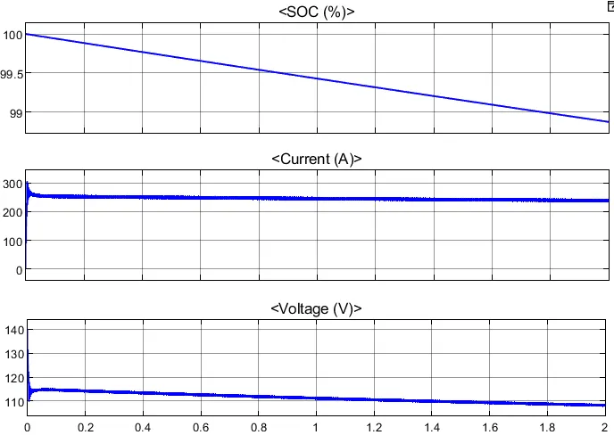
- From the above graph, it is seen that the battery is discharge from the 100 % to the 98 % during the travelling of the vehicle.
- The current drawn from the battery is near about 250 Amp.
- The battery voltage is 120 V.
Motor output Results:
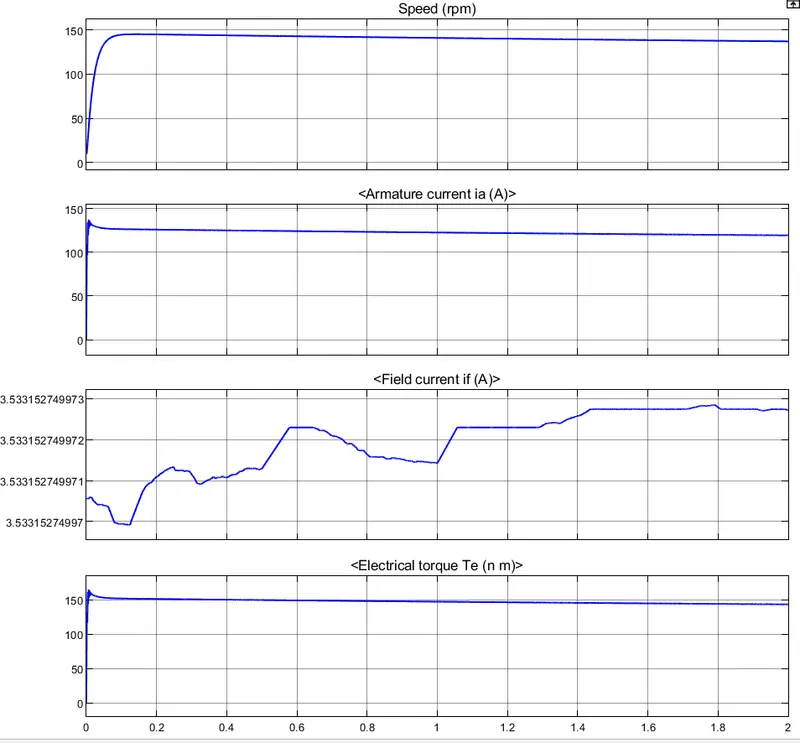
- In the above graph, the speed of the motor is approximately 140 RPM, armature current is 120 Amp and the the field current is achieving the steady state after 1.4 sec.
Performance of the Vehicle:
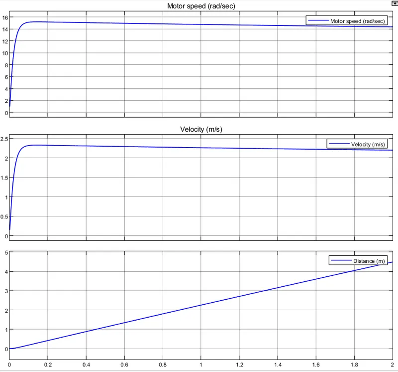
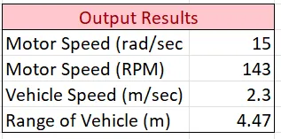
- In the above graph, the angular speed of the vehicle is 15 rad/sec.
- The vehicle is travelling with the speed of 2.3 m/s.
- The distance travelled by the vehicle is 4.47 m.
The total parameter consider for the modelling are:
Towing vehicle tyre specification:
Calculating total power required by towing vehicle:
Sizing of powertrain block:
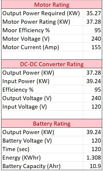
Output Performance Calculation: