Project-1: Powertrain for aircraft in runways
Part A:
1.
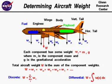
An airplane is a combination of many parts; the wings, engines, fuselage, and tail, plus the payload and the fuel. Each part has a weight associated with it which the engineer can estimate, or calculate, using Newton's weight equation:
w = m * g
where w is the weight, m is the mass, and g is the gravitational constant which is 32.2 ft/square sec in English units and 9.8 meters/square sec in metric units. The mass of an individual component can be calculated if we know the size of the component and its chemical composition. Every material (iron, plastic, aluminum, gasoline, etc.) has a unique density. Density r is defined to be the mass divided by the volume v:
r = m / v
If we can calculate the volume
m = r * v
The total weight W of the aircraft is simply the sum of the weight of all of the individual components.
W = w(fuselage) + w(wing) + w(engines) + w(payload) + w(fuel) + ...
To generalize, if we have a total of "n" discrete components, the weight of the aircraft is the sum of the individual i component weights with the index i going from 1 to n. The greek mathematical symbol sigma is used by mathematicians to denote this addition. (Sigma is a zig-zag symbol with the index designation being placed below the bottom bar, the total number of additions placed over the top bar, and the variable to be summed placed to the right of the sigma with each component designated by the index.)
W = SUM(i=1 to i=n) [wi]
This equation says that the weight of the airplane is equal to the sum of the weight of "n" discrete parts. The continuous change can be computed using integral calculus. The sigma designation is changed to the integral "S" shaped symbol to denote a continuous variation.
W = S w(x) dx
The discrete weight is replaced with w(x) which indicates that the weight is some function of distance x. If we are given the form of the function, there are methods to solve the integration. If we don't know the actual functional form, we can still numerically integrate the equation using a spread sheet by dividing the distance up into a number of small distance segments and determining the average value of the weight over that small segment, then summing up the value.
The weight of the aircraft is needed to be calculated by the pilot for every flight to ensure the aircraft remains within weight limitations set by the manufacturer. These limitations are to ensure the aircraft is able to perform and recover from all flight manoeuvres and withstand structural loading.
|
Aircraft |
Empty Weight |
Max Fuel Weight |
Max Cargo Weight |
Max Gross Takeoff Weight |
|
285,000 kg |
300,000 kg |
190,000 kg |
640,000 kg |
|
|
277,000 kg |
254,000 kg |
84,000 kg |
575,000 kg |
|
|
220,100 kg |
194,000 kg |
134,000 kg |
447,700 kg |
|
|
168,000 kg |
175,000 kg |
54,000 kg |
372,000 kg |
|
|
168,000 kg |
145,500 kg |
67,100 kg |
352,000 kg |
|
|
135,500 kg |
101,500 kg |
57,300 kg |
254,000 kg |
|
|
44,700 kg |
24,000 kg |
20,200 kg |
85,000 kg |
|
|
42,600 kg |
22,100 kg |
20,000 kg |
68,000 kg |
|
|
28,800 kg |
13,000 kg |
13,100 kg |
48,000 kg |
|
|
24,500 kg |
21,900 kg |
3,000 kg |
45,200 kg |
|
|
21,850 kg |
8,900 kg |
2,760 kg |
36,500 kg |
|
|
17,800 kg |
5,300 kg |
8,500 kg |
28,000 kg |
|
|
6,300 kg |
2,750 kg |
1,300 kg |
9,700 kg |
|
|
4,700 kg |
2,650 kg |
1,000 kg |
7,800 kg |
|
|
3,200 kg |
1,450 kg |
1,900 kg |
5,400 kg |
|
|
1,450 kg |
155 lbs |
560 kg |
2,000 kg |
|
|
1,150 kg |
200 kg |
385 kg |
1,660 kg |
|
|
990 kg |
235 kg |
520 kg |
1,630 kg |
|
|
1,000 kg |
220 kg |
430 kg |
1,630 kg |
|
|
770 kg |
170 kg |
255 kg |
1,100 kg |
2.
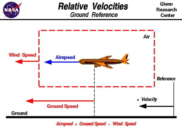
Wind Speed
For a reference point picked on the ground, the air moves relative to the reference point at the wind speed. Notice that the wind speed is a vector quantity and has both a magnitude and a direction. Direction is important. A 20 mph wind from the west is different from a 20 mph wind from the east. The wind has components in all three primary directions (north-south, east-west, and up-down). In this figure, we are considering only velocities along the aircraft's flight path. A positive velocity is defined to be in the direction of the aircraft's motion. We are neglecting cross winds, which occur perpendicular to the flight path but parallel to the ground, and updrafts and downdrafts, which occur perpendicular to the ground.
Ground Speed
For a reference point picked on the ground, the aircraft moves relative to the reference point at the ground speed. Ground speed is also a vector quantity so a comparison of the ground speed to the wind speed must be done according to rules for vector comparisons.
Airspeed
The important quantity in the generation of lift is the relative velocity between the object and the air, which is called the airspeed. Airspeed cannot be directly measured from a ground position, but must be computed from the ground speed and the wind speed. Airspeed is the vector difference between the ground speed and the wind speed.
Airspeed = Ground Speed - Wind Speed
On a perfectly still day, the airspeed is equal to the ground speed. But if the wind is blowing in the same direction that the aircraft is moving, the airspeed will be less than the ground speed.
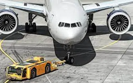
- Although most aircraft are capable of moving themselves on the ground, it is not typically done due to the following reasons,
- The jet blast from the engines can damage the terminal building and nearby equipment. It can even throw away people standing nearby.
- Engines can blow sand and debris.
- Engines can suck in sand and debris which can cause serious damage to the engine.
- It is easier for the truck driver to see the surroundings better than the pilot sitting in the cockpit with limited windows.
- The pushback truck driver knows the airport better than the pilot.
- The plane engines are very loud. This noise can add up substantially when multiple planes are moving around the airport. It won't be a pleasant experience for people sitting inside the terminal, as most people don't even like the sound of powerful motor-bikes.
- It saves fuel.
- Modern planes are huge. It is difficult to navigate such gigantic structures through limited space. An A380 is eight stories high. The pilots won't be able to see anything directly in-front of them or anything behind the wings.
Actually, Pushback is for moving the aircraft backwards from the gate, and towing or taxing is the procedure to move the aircraft. These machineries are called as aircraft tugs. Aircraft tugs are real modern marvels, moving aircraft weight hundreds of tons all day, every day. A true pushback tug aims to allow the operator to have excellent visibility of the attaching mechanism between airplane and tug. While moving the aircraft in the reverse direction by applying the forward thrust, care must be taken because reverse thrust is unsafe when stopped or at low speed. This is because the nose may lift, dropping the tail on to the Tarmac. The cause is the engines being at some considerable height from the ground and the aircraft centre of gravity being just ahead of the main (rear) wheel set. Additionally, once moving backwards, if the aircraft's own brakes are used, the same can happen, i.e.. the plane can sit on its tail.
- Aircrafts are usually 'pushed' by ground vehicles known as tow vehicles such as tow trucks. It is used mainly to reverse an airplane from the terminal area, until it is in a position to move by itself. These tow trucks will only help move the aircraft to an area where the pilots can safely switch on the engines, not the runway! (Ground vehicles are rarely allowed to move on a runway (save for emergencies and inspection), and the aircraft is supposed to move to the runway by itself.
Aircrafts don't have powered wheels, and hence cannot move in reverse (let alone forward by themselves). Imagine a tiny jet strapped to one of your toy cars; that's essentially how airplanes work on the ground! They go where the engines push them towards. (Note: There is a mechanism known as reverse thrusters, which allow the engine air flow to be pushed towards the front, but that is highly risky manoeuvre, and is only used to reduce speed immediately after landing.)
Another reason to push back an aircraft to a safe area, is for safety reasons. The engines produce tremendous thrust from the exit, and an immense vacuum from the front; enough to suck in people, small vehicles, ground equipment etc. Hence, it is a common procedure to start the engines once it is cleared away from the terminal area and lined up on a taxiway (roads that lead to the runway).
- TAKE-OFF POWER: Take-off is the phase of fight in which an aerospace vehicle leaves the ground and becomes airborne. For aircraft that take off horizontally, this usually involves starting with a transition from moving along the ground on a runway. For balloons, helicopters, and some specialized fixed-wing aircraft (VTOL aircraft such as the Hamer), no nunway is needed. Takeoff is the opposite of landing
Take off performance can be predicted using a simple measure of the acceleration of the aircraft along the runway based on force equilibrium
The forces involved will be:
T-Thrust of propulsion system pushing aircraft along runway
D-Aerodynamic Drag of vehicle resisting the aircraft motion
F-Rolling resistance friction due to the contact o wheels or skids on the ground During take-off run the imbalance in these forces will produce an acceleration along the runway
dV/dt = (T-D-F)/m
where, dV/dt is the acceleration along the runway and
m is the mass of the vehicle
The procedure for take-off will be that the vehicle will accelerate until it reaches a safe initial thing speed. The pilot can then rotate the vehicle to an attitude to produce climb lift and it will ascend from the ground. The determination of this safe flying speed or rotation speed VR is a critical factor in determining take-off performance. Take-off rules vary slightly depending on the aircraft category. Small commuter aircraft should be considered as meeting FAR 23 rules. Transport category aircraft should comply with FAR 25 rules.
Small commuter aircraft:
For safety reasons VR is usually determined as being 1.1 x Vstall or 1.05 Vmin control
whichever is greater Stall speed. VSTALL is the lowest speed that the aircraft can be flown before the airflow starts to separate from wings as the angle of attack becomes too great. The wing is assumed in this case to be in take-off configuration or "clean”. It can be calculated based on knowledge of the aircraft take-off configuration and hence the maximum achievable lift coefficient CL (max).
As shown in the previous section, to maintain level flight the lift produced must equal the weight, hence the stall speed can be calculated
`V_(stall)=√(W/(1/2 C_(L(max)) ρS))`
Minimum control speed. VMC is a more complex calculation and requires knowledge of the stall characteristics of the tailplane and elevator. For conventional aircraft there is only a small difference between VR calculations based on stall speed or minimum control speed.
As well as rotation speed there are other safety considerations as shown in the following Figure
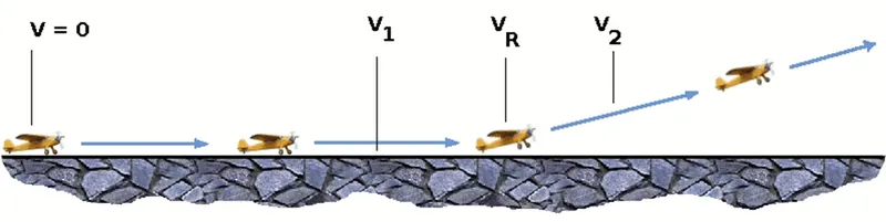
V1- Abort decision speed. Below this speed the take-off can be safely aborted. After this there will not be sufficient runway length to allow the aircraft to decelerate to a stop.
V2 – Safe climb speed. V2 must be no less than 1.2 * Vstall. Below this speed aircraft cannot attain sufficient climb rate.
Rolling Resistance:
The friction between aircraft and runway will be proportional to the normal force exerted by the aircraft on the runway.
F=μ(W−L)
The normal force will be the difference between Weight of aircraft and Lift, the friction coefficient will be typically of a magnitude of 0.02 for a standard tarmac runway.
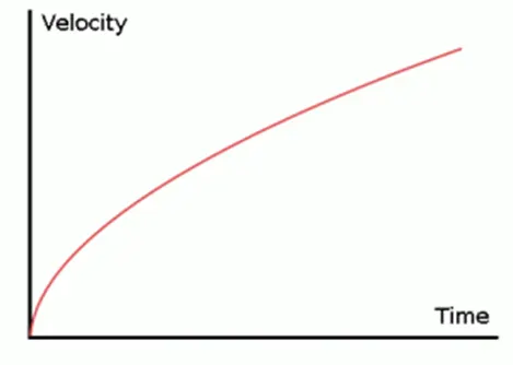
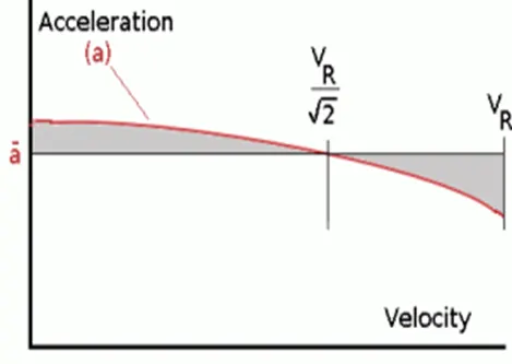
Average acceleration and distance to rotation
The rate of change of velocity can be predicted at any point on the take-off roll by substituting results for T, D and F into the initial equation for dV/dt. The subsequent velocity at any point can be found by integrating this resulting equation and the distance traveled found by then integrating the velocity.
Typically, acceleration will be dominated by the drag component as thrust, weight and friction are relatively constant during this period. This leads to the result shown where acceleration is inversely proportional to velocity squared.
Due to the quadratic nature of acceleration change, an average value, a , can be used for the take-off run. This average acceleration can be found at the point where,
`V=V_R/(√2)`
This average acceleration can be used to simplify calculations and the take-off run can be calculated as an equivalent constant acceleration over the complete period of time (tR) taken to get from 0 to VR. For a constant acceleration take-off calculation,
`VR=at_R` and distance travelled `s_1=(a t_R^2)/2`
Rearranging leads to a relatively simple calculation to predict distance to rotation point.
`s_1=V_R^2/(2a)`
From the rotation point, the end of the runway can be defined by the requirement to clear a 35ft obstacle at the end. During rotation it can be assumed that any residual excess thrust is absorbed in overcoming the lift induced drag as the aircraft begins to climb. Acceleration reduces and a constant flight speed during this climb phase can be assumed. The distance along the ground from rotation point to obstacle clearance point with thus be,
`s_2=35/(tan(ϴ)) ft`
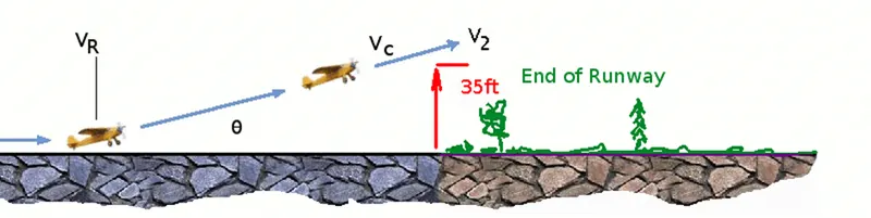
This distance estimate will require knowledge of the climb gradient which can be calculated by using the methods in the following section on Climb and Descent.
Landing:
The landing run can be calculated in a similar fashion to the take-off distance. The aim is again to minimise the distance.
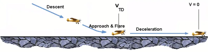
The touch down velocity should be approximately the stall speed of the aircraft in landing configuration. This will be achieved by a pitch manoeuvre during the flare portion of the approach which which increase drag an decelerate the aircraft to minimum flying speed.
The deceleration on the landing roll from VTD to V0 will be accomplished by braking and reverse thrust. This can be solved by the average acceleration approach that was used to estimate the take-off roll.
dV/dt = (-T-D-F)/m
The negative acceleration or deceleration value will be based on friction coefficient for maximum braking and the value of reverse thrust (if available).
Braking force:
Stopping an aircraft landing at 180-200 mph requires a lot of braking force. To do this, the aircraft has brake unit on each of the wheels on the main gear assembly. On landing, pilots should use aerodynamic braking by applying extra back-pressure on the stick or yoke. Extreme caution should be used when applying brakes at any significant speed, and only when the end of the runway is quickly approaching. Never step on the brakes to make a runway exit. Applying the brakes at too high a speed could burn the tires, wear out the brakes, or result in a ground loop or swerve.
Aircraft Disc Brake:
In the landing gear it is used to apply brake to the wheels while touching the ground. These brakes are operated hydraulically. In most modern aircraft they are activated by the top section of the rudder pedals ("toe brakes"). In some older aircraft the bottom section is used instead ("heel brakes"). Leversare used in a few aircraft. Most aircraft are capable of differential braking.
Tyre Design:
Aircraft tires may be tube-type or tubeless. They support the weight of the aircraft while it is on the ground and provide the necessary traction for braking and stopping. The tires also help absorb the shock of landing and cushion the roughness of takeoff, rollout, and taxi operations. Aircraft tires must be carefully maintained to perform as required. They accept a variety of static and dynamic stresses and must do so dependably in a wide range of operating conditions.
An aircraft tire is constructed for the purpose it serves. Unlike an automobile or truck tire, it does not have to carry a load for a long period of continuous operation. However, an aircraft tire must absorb the high impact loads of landing and be able to operate at high speeds even if only for a short time. The deflection built into an aircraft tire is more than twice that of an automobile tire. This enables it to handle the forces during landings without being damaged. Only tires designed for an aircraft as specified by the manufacturer should be used. It is useful to the understanding of tire construction to identify the various components of a tire and the functions contributed to the overall characteristics of a tire.
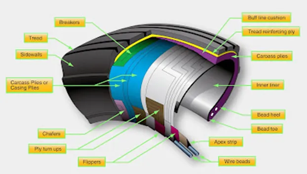
Aircraft Tyre Pressure:
Aircraft tires generally operate at high pressures, up to 200 psi (14 bar or 1,400 kPa) for airliners, and even higher for business jets. The main landing gear was typically inflated to 232 psi (160 bar), whilst its tail bumper gear tires were as high as 294 psi 20.3 bar. The high pressure and weight load tyres were a significant factor Tests of airliner aircraft tires have shown that they are able to sustain pressures of maximum 800 psi (55 bar: 5.500 kPa) before bursting. During the tests the tires have to be filled with water, to prevent the test room being blown apart by the energy that would be released by a gas when the tire bursts
Aircraft tires are usually inflated with nitrogen to minimize expansion and contraction from extreme changes in ambient temperature and pressure experienced during fight. Dry nitrogen expands at the same rate as other dry atmospheric gases (normal air is about 80% nitrogen but common compressed air sources may contain moisture, which increases the expansion rate with temperature The requirement that an inert gas such as nitrogen, be used instead of air for inflation of tires on certain transport category airplanes was prompted by at least three cases in which the oxygen in air-tilled tires had combined with volatile gases given off by a severely overheated tire and exploded upon reaching autoignition temperature. The use of an inert gas for the inflation eliminates the possibility of tire explosion.
Part B:
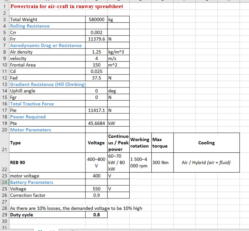
- With necessary assumptions, calculate the force and power required to push / pull an aircraft by a towing vehicle.
To push or pull an aircraft by a towing vehicle 3 type of forces will act on that vehicle. Those are - Rolling resistance force, Aerodynamic drag force and Hill climbing force
Rolling resistance force (Frr):
Rolling resistance is the force resisting the motion when a body rolls on a surface. It is the friction force that is needed to overcome to move a vehicle. The kinetic energy of the wheels is partially converted into heat. The rolling resistance is proportional to the normal force perpendicular to the rolling wheel and is approximated by the rolling resistance coefficient urr. Therefore, Equation that can be used for the rolling resistance force of the entire system is
Frr = urr * m * g
where, urr - Rolling resistance co-efficient (It depends on the tire material, tire structure tire temperature, road roughness and material etc)
m - Total mass of the vehicle (vehicle mass + payload) in kg
g-gravitational constant, that is 9.8 m/2
Aerodynamic drag force (Fad):
Aerodynamic drag force is the force acted on the body by the air opposing the vehicle. There are two components of this force, one is shape drag (due to the shape of the vehicle) and another is skin friction (due to friction between air and skin of the vehicle) When the vehicle moves the velocity of air near boundary is higher than the air surrounding Both the tug and the aircraft will experience some aerodynamic drag. For completeness, the aerodynamic drag force caused by the aircraft and towing vehicle can be given by Equation below:
Fad = (1/2) * ρ * V^2 * A * (Cd_t + Cd_a)
where p - Air density that is normally 1.25 kg/m^3
A - Frontal area of the vehicle in m2
Cd_t – Air-drag co-efficient of towing vehicle (it depends on frontal area, shape, protrusions, ducts, air passage etc.)
Cd_a - Air drag to efficient of aircraft depends on frontal area, shape, pinions, ducts, air passage etc)
V – Velocity of the vehicle in m/s
Hill Climbing Force (Fhc):
Hill Climbing force is the force needed to move the vehicle up a gradiant. The euation for hill climbing force is given below:
Fhc = m*g*sinφ
Where, m = Total mass pf the vehicle (Vehicle mass + payload)
g = gravitational constant (9.8m/s^2)
φ = inclination angle in radian
in this case there won’t be an inclination as the platform is flat therefore φ = 0.
Let us consider,
The Towing truck – Douglas Towbarless Aircraft Tractor, with specifications given below:
Gross weight = 35,000kg, Width = 3.4m, Height = 4.4m, Length = 8.4m,
Tyre size = 0.5715m, Velocity of the tug = 20kmph
To pull the Aircraft - Airbus-A310 with a specification:
Weight = 164,000kg, Height = 15.8m., Width = 43.9m, Drag coefficient = 0.0265
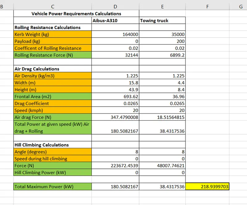
Therefore, from the excel calculator, the total power required by the towing truck is 218.9kW
B. Develop the model for the calculated force and power using Simulink.
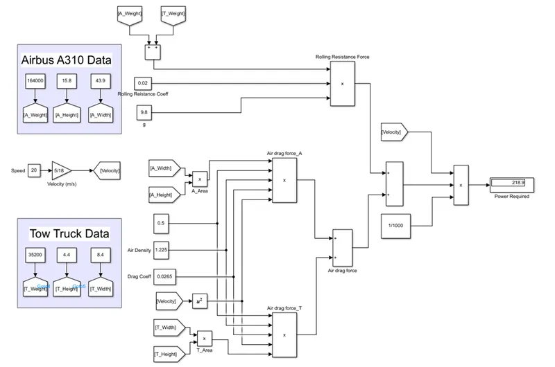
From the above model we can clearly see that both the data of tow truck and the aircraft is considered as input data and the rolling resistance force and air drag force is calculated to find out the power required by the tow truck to push or pull the aircraft. The total power required which is calculated is finally displayed in the display block.
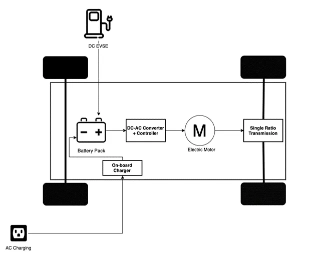
- A. Design an electric powertrain with type of motor, it’s power rating, and energy requirement to fulfill aircraft towing application in Simulink. Estimate the duty cycle range to control the aircraft speed from zero to highest. Make all required assumptions. Prepare a table of assumed parameters. Draw a block diagram of powertrain.
(Hint :DC7 Block)
Simulink Model:
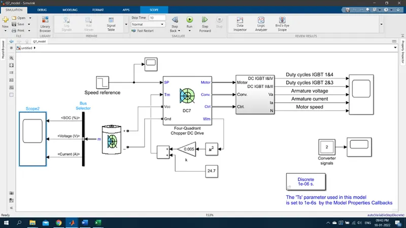
Estimation of Duty cycle As we know that the power required for towing vehicle to pushpull is equal to 218kW, For this model we have considered the motor AP-PWT-250KW-3000NM for drive train
Considering 250kW as continous power, so the voltage will be 400V, Battery power is considered to be 550V we know that duty cycles given by
d = Va/Vb = 400/550 = 0.7272.
There will also be loses due to the resistance of FET and inductance. Correction factor is considered to be 90% that makes us consider that there is 10% loss So the voltage which is demanded by the motor should be 10% more than the required voltage
d = 0.7272*(1+0.1) = 0.799 ~ 0.8,
so here the voltage demand is 440V from the battery.
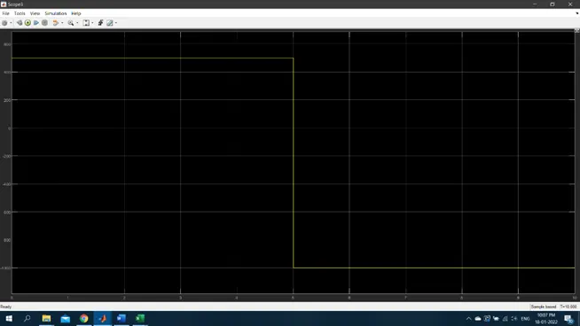
Speed input signal:
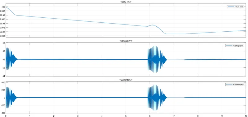
Battery Outputs:
Powertrain Output signal:
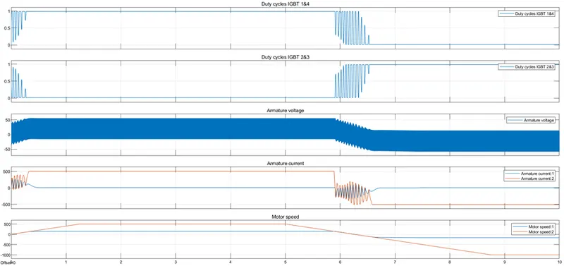
Powertrain Block Diagram:
B. Also, Design the parameters in excel sheet.