Week -2
-
- To create a Doorbell model using solenoid block according to the diagram given above:
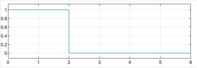
- I used a Discrete Pulse Generator Block to create a pulse for 2 seconds which is the converted into a physical signal by making it go through a Simulink-PS Converter, as the Switch Block is triggered by a physical signal.
- The Switch Block is connected to a Battery Block to provide the electrical signal needed to activate the Solenoid Block.
- Also the Electrical side is connected to an Electrical Reference to define all the initial points of the electrical parameters.
- The Mechanical side of the solenoid acts as the plunger of the door bell. So to read the movement of the plunger I map the movement of the plunger with a Scope.
- To map the mechanical movement of the Solenoid Block, I made the output side of the block to go through an Ideal Translational Motion Sensor Block to convert this mechanical movement to a Simulink signal.
- This signal is mapped by a Scope Block
The Simulink File of the block: https://drive.google.com/open?id=1-1hjE2J8VRTTI4Y-Na1mkyRGoBSeAIuH&authuser=febinansan%40gmail.com&usp=drive_fs
Input signal from the Discrete Pulse Generator Block:
Output diagram of the position of the plunger graph:
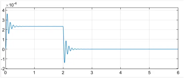
The output shows that the plunger is excited to its maximum position and it settles on that position after a short time oscillation period while the switch is still at on position. And once the switch is at off position, the plunger comes to normal position after a very short period oscillation similar to before.
-
To Use the Thermistor to sense the temperature of a heater & turn on or turn off the fan:
- First I selected a Signal Builder Block to create a signal which corresponds the given temperature condition. Though I first converted the temperature given in the condition to Kelvin measure from Celsius scale as every heat blocks inside Simulink is at Kelvin scale at default mode.
- This created signal is then given to a Controlled Temperature Source Block through a Simulink PS Block to convert this signal to temperature.
- This temperature signal is then given to a Thermistor Block, which is connected to a battery and a resistor circuit.
- The voltage across the resistor is observed with a Voltage Sensor Block with a display block, connected across the resistor.
- The voltage value when the temperature is at 25degree Celsius is noted and the Switch Block connected to it is designed to give an output of 48 when the condition is satisfied.
- This output value is then used to trigger the Controlled Voltage Source Block. This block energizes a circuited connected with a DC Motor Block, which acts as the Fan.
- The output of the DC Motor Block is observed the Ideal Rotational Motion Sensor
The Simulink File of the block: https://drive.google.com/open?id=1-B1Kd8q5vVUHtlPV9o314B0KxEgdYddP&authuser=febinansan%40gmail.com&usp=drive_fs
The angular position graph of the Ideal Rotational Motion Sensor, shows that the fan is on only When Temperature is above 25 degree celsius.