Week - 4
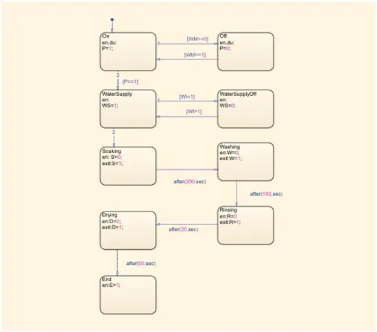
- The Washing Machine model is created with a stateflow logic. The states of the washing machine is created inside the chart. There is an On state and an Off state initially and then the control goes to the water supply state to check if there is water supply or not.
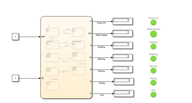
Then the next states indicate the states of the operation of the washing machine. Input of the chart is Washing Machine power on and off condition and Water supply on and off condition. The output shows the states of the every step of the modes of operation. These outputs are shown through display and also represented by a lamp. The model :
- The Gear Model is done with the Sateflow logic. The gear changing logic is implemented inside the chart in the model given below:
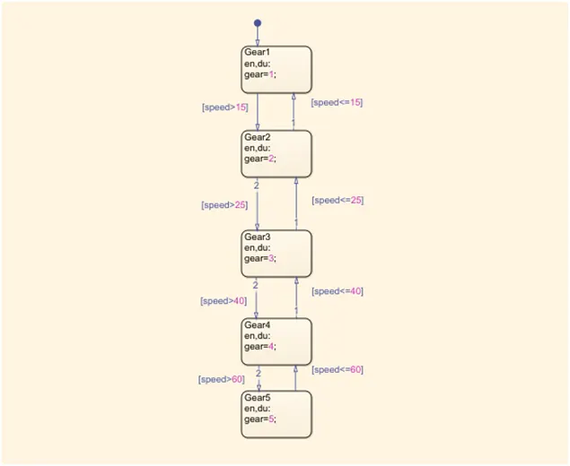
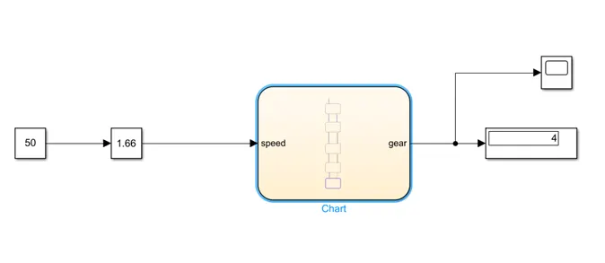
The speed Variable is the input of the chart, which indicates the speed of the vehicle. This speed input is given through a constant and a slider block. And gear variable is the output of the chart which indicates the current gear. This gear is then shown through a display. The model: