Project-1: Powertrain for aircraft in runways
AIM:- To Study on Overview of an aircraft & Its Parts.
OBJECTIVE:-
- To list out the total weight of various types of aircrafts.
- Compare difference between Ground Speed & Air Speed.
- To study about take off power, tyre design, rolling resistance, tyre pressure, brake forces when landing.
- To calculate the force and power required to push / pull an aircraft by a towing vehicle &Develop the model for the calculated force and power using Simulink.
- To Design an electric powertrain with type of motor, it’s power rating, and energy requirement to fulfill aircraft towing application in Simulink.
- To Estimate the duty cycle range to control the aircraft speed from zero to highest. Make all required assumptions. Prepare a table of assumed parameters. Draw a block diagram of powertrain Using DC7 block.
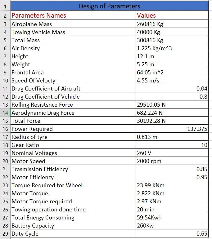
- Design the Parameter in Excel Sheet.
INTRODUCTION:-
An aircraft is a machine that is able to fly by gaining support from the air.An airplane is a flying vehicle that has fixed wings and engines or propellers that thrust it forward through the air. The essential components of an airplane are a wing system to sustain it in flight, tail surfaces to stabilize the wings, movable surfaces to control the attitude of the plane in flight, and a power plant to provide the thrust necessary to push the vehicle through the air. Provision must be made to support the plane when it is at rest on the ground and during takeoff and landing.
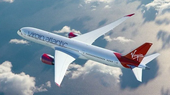
An aircraft in straight-and-level unaccelerated flight has four forces acting on it.It force name as turning, diving, or climbing flight, additional forces . These forces are lift, an upward-acting force; drag, a retarding force of the resistance to lift and to the friction of the aircraft moving through the air; weight, the downward effect that gravity has on the aircraft; and thrust, the forward-acting force provided by the propulsion system. Generally in Small Plane used in this IC engine.The are various type of engine and It is Bases on arragement of Cylinder. The Four to eight cylinders may be aligned one behind the other in an in-line engine; the cylinders may be upright or inverted, the inverted having the crankshaft above the cylinders. V-type in-line engines, with the cylinders arranged in banks of three, four, or six, also are used.
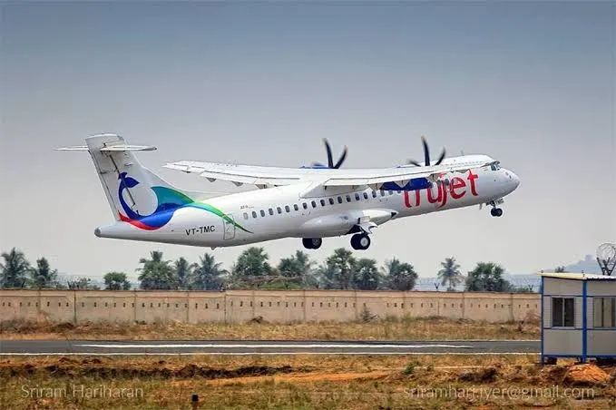
An early type of engine in which the propeller is affixed to the body of the cylinders, which rotate around a stationary crankshaft, is the rotary engine. Modern rotary engines are patterned after the Wankel principle of internal-combustion engines.
Automobile and other small engines are modified for use in homebuilt and ultralight aircraft. These include two-stroke, rotary, and small versions of the conventional horizontally opposed type.
PART:-A
Question:-1] Search and list out the total weight of various types of aircrafts.
Ans:-
What is Payload:-
The weight of all persons and Items of load carried in an aircraft for Which a charge is being paid.It is calculated by following formulas- Payload = Passenger and Cargo Weight.
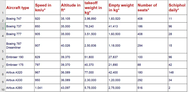
Total Weight of various type of Aircrafts are following:-
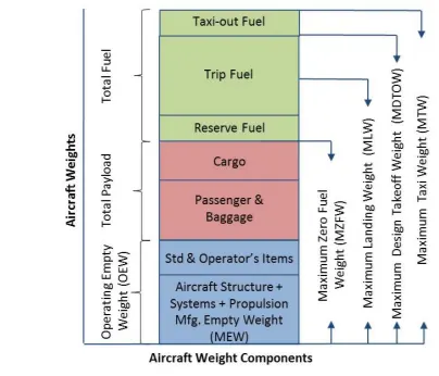
1] The Maximum Take-off Weight (MTOW) :-
- It is means the maximum weight for takeoff as limited by airplane strength and airworthinessrequirements. This is the maximum weight at the start of the takeoff.
- The Maximu Take-off Weight of an Aircraft is Fixed.
- It ia usually specified in Unit of Kg.
2] Maximum Landing Weights (MLW):-
It is means the maximum weight for landing as limited authorized by airplane strength and airworthiness requirements
3] Maximum Zero-fuel Weight (MZFW)
- It is means the maximum weight permitted before usable fuel andother specified usable fluids are loaded. The MZFW is limited by strength and airworthiness requirements.
- When an airplane is being loaded with crew, passenger,baggages and it is the most important to ensure that the Zero fuel weight does not exceed the Maximum Zero Fuel Weight.
- It is a weight of the fuel required for and burnt during a flight.
- It can be calculator as follows.
- Flight Fuel = Fuel Flow * Flight Time.
4] Maximum Taxi Weight:-
It is the weight for ground maneuver as limited by Airplane strength and Air workthiness requirement.
5] Operators Empty Weight:-
It is The weight of the aircraft prepared for service and is composed of the Manufacturer Empty Weight plus operator items.
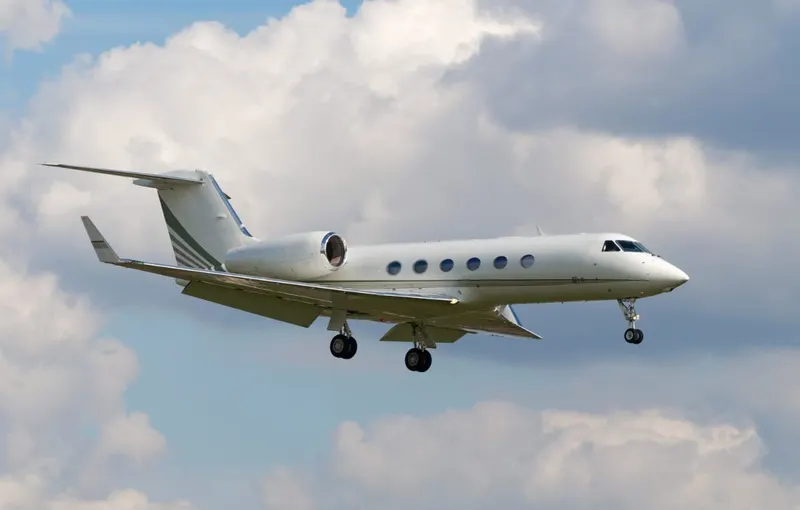
Airplanes:-
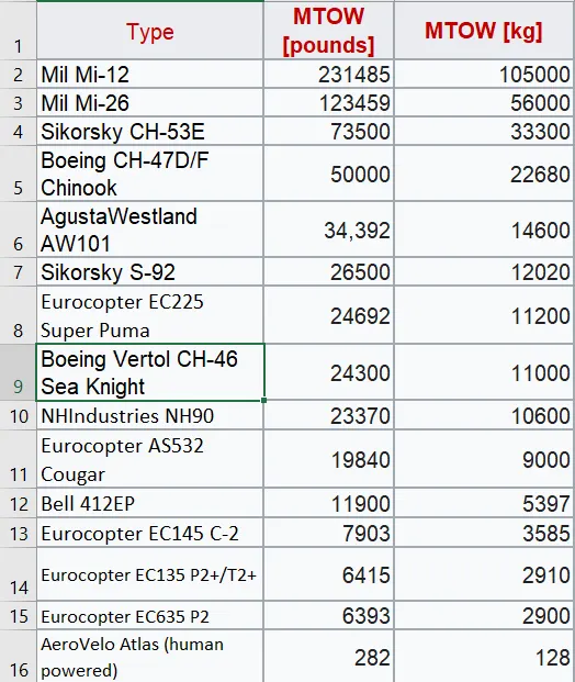
Helocopters:-
Fig:- Sikorsky CH-53E Super Stallio Fig:- Eurocopter AS532 Cougar Fig:- Boeing CH-47 Chinook
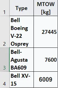
Convertiplanes:-
Fig:-Bell Boeing V-22 Osprey . Fig:- Bell/Agusta BA609. Fig:- Bell XV-15.
Referances Link:- https://en.wikipedia.org/wiki/List_of_airliners_by_maximum_takeoff_weight
Question:-2] Is there any difference between ground speed and air speed?
Ans:-
Air Speed:-
- A Airspeed is simply the speed at which an aircraft is moving relative to the air it is flying in.
- it’s also the speed at which the air is flowing around the aircraft’s wings.
- Airspeed cannot be directly measured from a ground position, but must be computed from the ground speed and the wind speed
- Airspeed = Ground Speed - Wind Speed
Ground Speed:-
- Ground speed is defined as the aircraft’s horizontal speed relative to the surface of the Earth,
- One thing that should be noted here is that it’s its horizontal rather than vertical speed.
- an aircraft climbing completely vertically would have a ground speed of zero.
Example:-
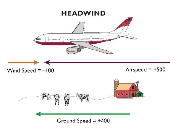
The wind is blowing 20 mph towards the west and the airplane takes off going east. The wind is blowing towards the aircraft which we call a headwind. Since we have defined a positive velocity to be in the direction of the aircraft's motion, a headwind is a negative velocity. While the plane is sitting still on the runway, it has a ground speed of 0 and an airspeed of 20 mph:
Airspeed = Ground Speed (0) - Wind Speed (-20)
= 20 mph
Question:-3] Why is it not recommended to use aircraft engine power to move it on the ground at Airport?
Ans:-
An Airplanes move on the ground the same way they move through the air: Using the thrust generated by their turbine engines. The wheels turn freely and merely support the weight of the plane.Engine power is used all the time to move aircraft on the ground. The engine power is used all the time in the ramp. They do get pushed back because only aircraft with engines on the tail can power-back due to FOD.
Question:-4] How an aircraft is pushed to runway when its ready to take off?
Ans:-
An Airplanes have engines, and they can use them to move forward along the ground. So they push themselves to the runway.It is true that most of the time, a small vehicle is needed to push the larger commercial airplanes backwards away from the terminal building, because even if a plane can reverse it’s thrust, it’s not always safe to hit the buildings with that reverse thrust. So the little trucks push the bigger planes back away from the buildings, but after that, the planes can apply a small amount of engine power to roll forward just as all airplanes can.Aircraft push themselves to the runway.
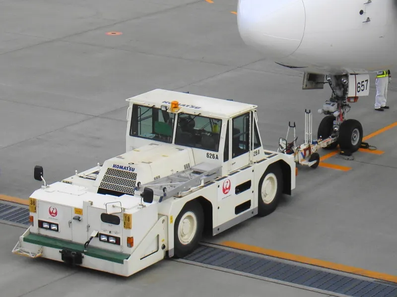
Large jetliner passenger aircraft are pushed away from the passenger loading gate by a tug. This is a machine with wheels, some form of power such as an internal combustion engine, or a battery. When the large aircraft is being pushed backwards, there is someone on each wing tip. They are looking out to make sure nothing will touch the aircraft. The whole idea is to avoid expensive crunching noises.
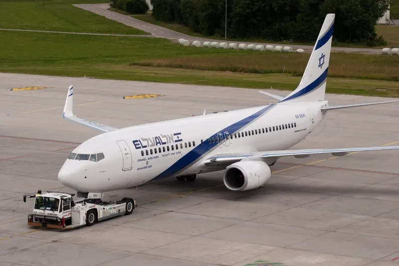
when you hear a crunching sound and a modern airliner is involved, it will be expensive beyond your wildest imagination.
An airliner might be pushed backwards off the ramp, and onto a taxi way. Then the engines can start, the aircraft can proceed forward under its own power. A twin engine jet might not start the second engine until it is close to takeoff runway, clearance is certain.A piston engine can run at idle power using only a small percentage of the fuel consumption used at operating power level.
Question:-5] Learn about take off power, tyre design, rolling resistance, tyre pressure, brake forces when landing.
Ans:-
Take-Off Power:-
The Take-off Power is the amount of power that an engine is allowed to produced for a limited period of time for take-OFF.
The normal take-off is one in which the airplane is headed into the wind, or the wind is very light. Also, the takeoff surface is firm and of sufficient length to permit the airplane to gradually accelerate to normal lift-off and climb-out speed, and there are no obstructions along the takeoff path.
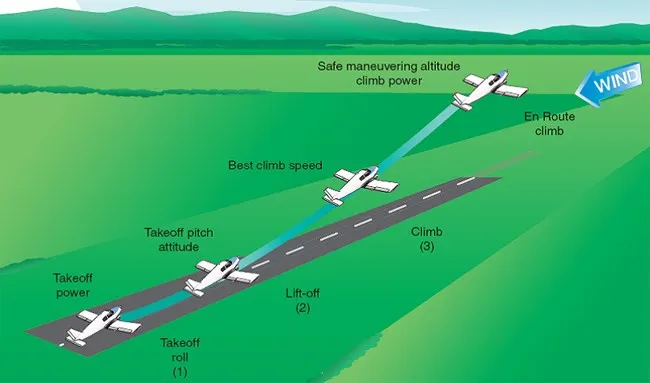
the airplane should be carefully aligned with the intended takeoff direction, and the nose wheel positioned straight, or centered. After releasing the brakes, the throttle should be advanced smoothly and continuously to takeoff power. An abrupt application of power may cause the airplane to yaw sharply to the left because of the torque effects of the engine and propeller.
There are two reasons for making a takeoff as nearly into the wind as possible:
- Aircraft speed will be less, therefore reducing wear and stress on landing gear
- Shorter ground roll and therefore much less runway length
Tyre Design-
The tyres fitted to an aircraft are designed to support the full weight of that aircraft while on the ground, as well as the static and dynamic loads generated during taxi, take-off and landing. The largest loads that the wheel/tire assembly sees occur during landing and are characterised by high speeds and large impact loads which deforms the tires, loading the wheel at the flanges. This tutorial focuses on the design and construction of the wheel and tire assembly as fitted to a typical aircraft.
There are Two types of tires are used in aircraft applications
1] bias-ply tires
2] radial tires.
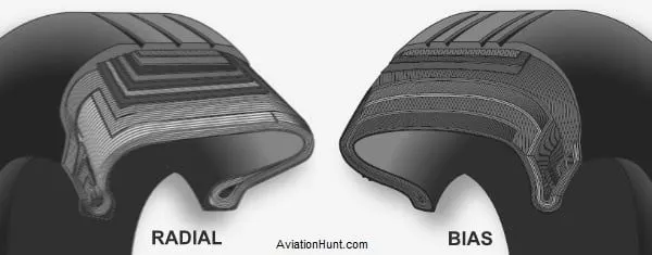
Fig:- Cut Section of Bias-ply and Radial tyre
1] Bias-ply tyre:- A bias-ply tyre has the fabric bias oriented with and Across the direction of rotation and the sidewall.Since the fabric can stretch on the bias,the tyre is flexible and can absorb loads.Tyre Strength is obtained by adding plies.
2] Radial tyre:- A radial tyre has the fibre strands of the ply fabric oriented with and at 90 Degree to the direction of rotation and the tyre sidewall. This restricts flexibility bidirectionally and the flexibility of the sidewall while it strengthens the tyre to carry heavy loads.
The Radial tyres are a newer design. The traditional aircraft were using cross Ply tyre. The choice of tyre in aircraft only depend on manufacture type certificate data sheet. The Radial tyres are in demand because of their long terms value, although they are more expensive than bias-ply tyre.
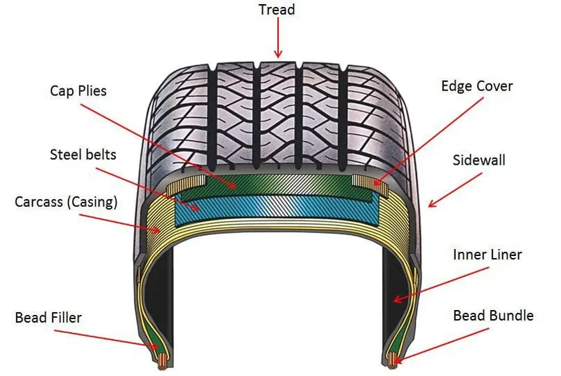
Fig:- Tyre Cut Section
Tire Terminology:-
Ply Rating:- The ply rating is used to indicates an index to the load rating of the tire.When tires were made from cotton cord,ply rating did indicates the actual number of pilies in the carcass. with the development of highere strenght fibrics such as nylon. the ply rating has been replacedto mens an index of cascass strength the load carrying capacity.
Rated load:- This is a maximum allowable load that the tyre can carry at the specified rated inflation pressure.
Rated Pressure:- The rated pressure is the maximum inflation pressure to to match the load rating.Aircrafts tire pressure are given for an unloaded tire.The pressure are 4% as a result of a reduction in air volume.
Outside Diameter:- This measurement is taken at the circumferential center line of an inflated tire.
Section Width:- This measurement is taken at the Maximum cross sectional width of an inflated.
Ram Diameter:- This is the nominal diameter of the wheel on which the tire is mounted.
Section Height:- This measurement can be calculated by using following formulas,
Section Height= Outside Diameter-Ram Diameter/2
Aspect ratio:- This measure of the tire cross section shape, This can be calulate for following formulas,
Aspect ratio= Section Height/Section Width
Flange Height:- This is the height of the wheel rim flange.
Flange Diameter:- The Diameter of the Wheel including the flange.
Free Height:- This measurement can be calculated by using following formulas,
Free Height= Outside Diameter- Flange Diameter/2
Static Loaded Radius:- This is the mesurement from the center of the axel to the runway for a loaded tire.
Loaded Free Height:- This measurement can be calculate for following formulas,
Loaded Free Height=Static load radius-Flange Diameter/2
Tire Deflection:- It is used when talking about aircraft tires is the amount of deflection it see when rolling under load.The most aircraft tire are design to operate at 32% deflection. The tems % of deflection is a calculate using following formulas,
% Deflection = Free Height- Loaded free Height/Free Height
Service Load:- The load on the tire at maximum aircraft takeoff Weight.
Service Pressure:- The corresponding pressure to provide proper deflection at service load.
Rated Speed:- The Maximum speed to which the tire is quelified.
Tyre Size:-
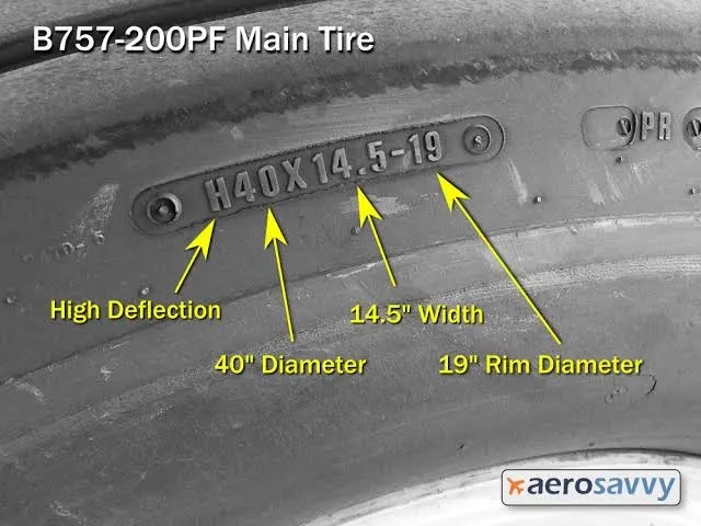
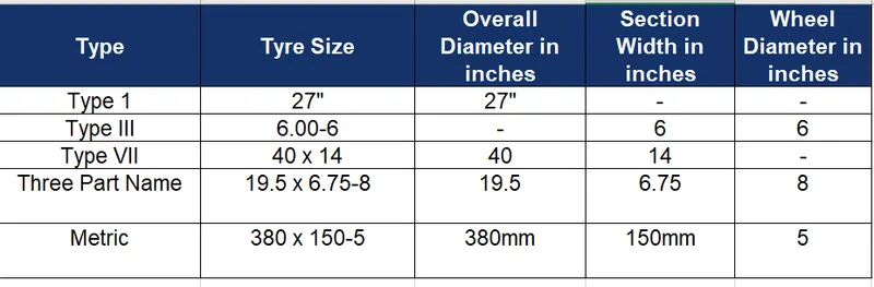
- The type I The very earliest of tyre designs and their outside diameter e.g. 27''
- The type III tyres are generallythe aviation and it include the most widely used sizes such as 5.00-5 and 6.00-6. These measurements refer to the section width of a tyre and also the rim ledge diameter (or the hole in the middle) hence a 6.00-6 is 6 inches wide and sits on 6-inch wheel.
- Three Part Name Sizes cover most of today’s designs and typically describe the Outside Diameter, Section Width and Rim Ledge Diameter e.g. 15×6.00-6, the tyre is 15 inches tall, 6 inches wide and sits on a 6-inch wheel.The ‘H’ which identifies the tyre as having a higher percentage deflection.
- Metric sizes are the same as three part name sizes but the Overall Diameter and Section Width are replaced with millimeters but the rim sizes remain in inches, e.g. 380×150-5, its imperial equivalent is a 15×6.00-5.
- Radial tyres are also the same as three part name sizes but the dash preceding the rim diameter is replaced with the letter ‘R’ e.g. 32×8.8R16.
Rolling Resistance:-
- The force that resists the motion of a body rolling on a surface is called the rolling resistance or the rolling friction.it is also called as Rolling Friction force.
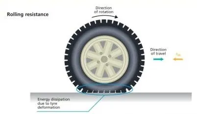
- Rolling resistance is the combination of forces that work against the forward motion of your vehicle. The weight of the vehicle, gravity and inertia, the amount of friction between the tires and the road surface, and air drag all play a part. The more rolling resistance, the more power it takes to propel a vehicle.
- There is a frictional force between the surface of the object and the rolling surface that cause the object to rotate.
- The frictional force is considered rolling friction. We can calculate that rolling friction as:-
`Frr=Crr*F`
Where,
Frr = is the rolling resistance friction
F = is the normal force
Crr = is the coefficient of rolling resistance friction
We have a coefficient of rolling resistance friction, which is a property of the relationship between the object's material and the surface's material. The Constant value of Crr table as shown in following:-
Tyre Pressure:-
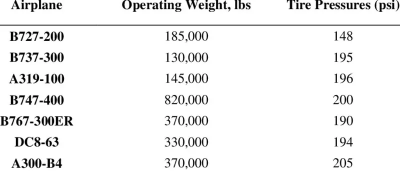
Tires are one of the most vitally important.The Aircraft generlly operate at High pressure.Upto 200psi. The 14 bar, 1400Kpa for Airlines.The high-flying rubber is typically inflated to 200 psi, roughly six times what you put in an automobile tire, and the tires on an F-16 fighter are pumped to 320 psi. A fully loaded 747-8 weighs nearly a million pounds. All that weight rides on a handful of tires. Automobile tires are pressurized to around 30-40 psi.
The Various type of Airplane and there Tire Pressure in Psi as shown in following:-
Brake Forces when landing:-
The Braking System is one of the Crucial element in the aviation sector.The Advanced of technologies such as Thrust reversers,Spoilers,disc brake etc.Has transformed the commercial as well as military aviation extensivety.Their uses ensured better utilisation of energy.Which would otherwise go waste and also reduces the dangers of accident due to skidding and shock cooling.Now day the material thermal and mechanical properties are being used such as carbon fibre, ceramics etc.This ensures the longer life of brake and incresesd the realiability and Safety.Aircraft brakes stop a moving aircraft by converting its kinetic energy to heat energy by means of friction between rotating and stationary discs located in brake assemblies in the wheels.
Spoilers:- The Spoilers that are used in flight as speed brakes as well as on landing.) While the spoilers provide some drag, their primary purpose is to stop the plane from actually flying, putting all of the weight on the landing gear and in turn making the brakes that much more effective.
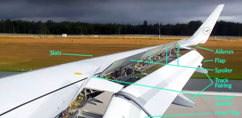
Fig:- Spoilers Speed Brake
Autobrakes:-
The Wheel brakes are usually selected to engage automatically after landing.The crew will decide which is the most appropriate to use for every landing depending upon factors like the length of runway, if it is wet or dry, or if the pilots want to exit the runway at a particular point. “For a short wet runway you might select autobrake 3, or MED on the Airbus. For a long dry runway you might select autobrake 1 or LOW on the Airbus,” his transition from autobrake to manual brakes can be quite difficult to do smoothly especially in a crosswind, as you will be steering the aircraft with the rudder pedals and then have to press down on the tops of the rudder pedals evenly to deactivate the autobrakes and start manual braking.
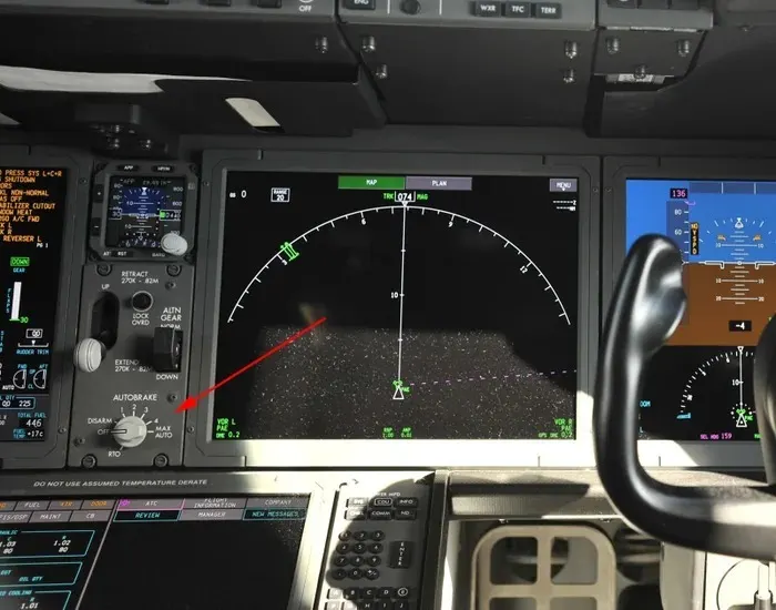
Fig:- Autobrake
Disc Brake:-
The Aircraft typically used disc and multi-disc brakes.This brake consist of rotating disc attached to the wheel assembly.the brake pad is made of material names as asbestos,ceramics, carbon.When brake pedal is pressed,The brake fluid under pressure flow from master cylinder to the slave cylinder via tubes.The piston forces the brake pad against the rotating part.The friction between the brake pad and disc surface,resist its rotating rotating motion and stop it.These day the disc are provided with slots for better heat dissipation at high temperature.
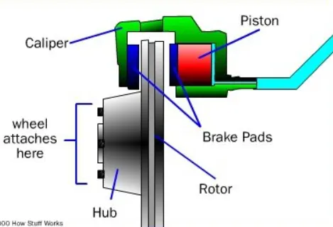
Fig:- Disc Brake
The kinetic energy (KE) is a function of mass (m) and velocity (v) according to the equation:-
`K.E=1/2*m*v^2`
PART:-B
Question:-6] A. With necessary assumptions, calculate the force and power required to push / pull an aircraft by a towing vehicle.
Ans:-
Fig:- Boeing 777 Airplane. Fig:- Airbus A318.
Formulas Used in this calculation are Following :-
1] Rolling Resistance Force (Frr) = `Crr*m*g`
Where, Frr= Rolling Resistsnce Force in N
Crr= Coefficient of Rolling resistsnce
g = Gravity 9.81
2] Aerodynamic Force (Fad)=`1/2*Cd*rho*A*V^2`
Where, Fad= Aerodynamic Force in N
Cd = Drag Coefficient
rho = Air Density in Kg/m^3
A = Frontal Area in m^2
V= Velocity of Vehicle in m/s
3] Total Force (Ft) = `Frr+Fad`
Where, Frr= Rolling Resistance in N
Fad= Aerodynamic Fornce in N
4] Power Required (Pr) = `Ft*V`
Where, Ft= Total Force in N
V= Velocity of Vehiclein m/s
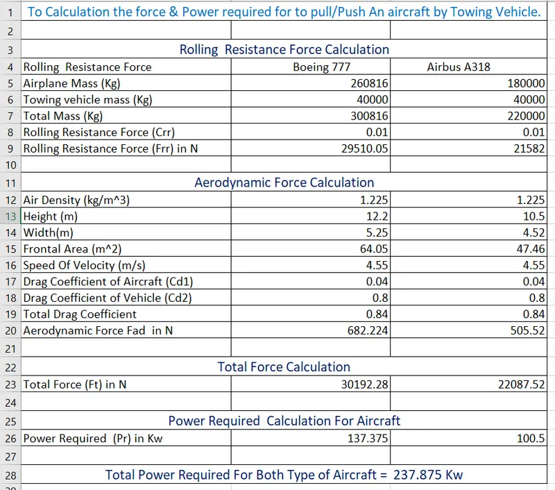
B. Develop the model for the calculated force and power using Simulink.
Ans:-
Boeing 777:-
Model for the Calculated force and Power required:-
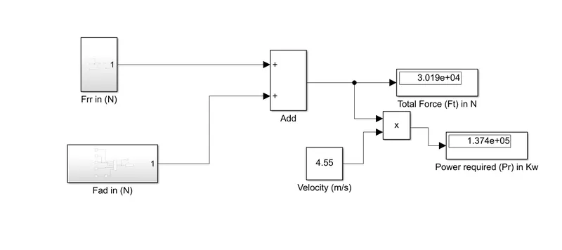
Fig:- Simulink model for calculate force and power.
Subsystem in Rolling Resistance Force Block:-
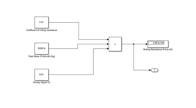
Fig:- Subsystem in Frr Block
Subsystem in Aerodynamic Force Block:-
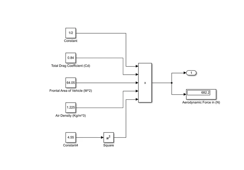
Fig:- Subsystem in Fad Block
Question:-7] A. Design an electric powertrain with type of motor, it’s power rating, and energy requirement to fulfill aircraft towing application in Simulink. Estimate the duty cycle range to control the aircraft speed from zero to highest. Make all required assumptions. Prepare a table of assumed parameters. Draw a block diagram of powertrain.
(Hint :DC7 Block)
Ans:-
Formules used for below Calculation:-
1] `Tw=Frr*r`
Where,
Tw= Torque required for the wheel (KNm)
Ft = Rolling Resistance Force (N)
r = Radius of wheel (m)
2] `Tm=(Tw)/(G*etat)`
Where,
Tm= Motor Torque (KNm)
G= Gear ratio
3] `Tmr=(Tm)/(etam)`
Where,
Tmr=Motor Torque Required (KNm)
ηm=Motor Efficiency (%)
4] `Pt=(Pr)/(etam+etat)`
Where,
Pt=Total power required by the motor considering all efficiency (Kw)
Pr= Power required for Aircraft (Kw)
5] `Et=Pt*t`
Where,
Et= Total Energy Consuming (Kwh)
T= Time (Houres)
6] `Dc=(Pt)/(Br)`
Where,
Dc= Duty Cycle
Br= Battery rating
Calculation:-
Input data:-
Rolling Resistance force for Aircraf(Frr)=29510.05 N (29.510KN)
Power Required Force Aircraft(Pr)=137.375Kw
Radius of Tyre (r) = 0.813meter
Gear Ratio (G)=10
Motor Efficiency (ηm)=95% (0.95)
Transmission efficiency (ηt)=85% (0.85)
1] Required Torque for the vehicle wheel :-
Tw=Frr*r
=29.510*0.813`
`=23.99KNm`
Therefore,The Torque Required for the Vehicle wheel is 23.99KNm.
2] Motor Torque:-
`Tm=(Tw)/(G*etat)`
`=(23.99)/(10*0.85)`
`=2.822 KNm`
Therefore,The Torque for Motor is 2.882KNm.
3] Required Motor Torque:-
`Tmr=(Tm)/(etam)`
`=2.822/0.95`
`=2.97KNm`
Therefore, The Torque required for Motor is 2.97KNm.
4] Find Total power Required for Motor Considering all Efficiency:-
`Pt=(Pr)/(etam+etat)`
`=(137.375)/(0.95*0.85`
`=170.124Kw`
Let, we have consider The towing Vehicle operation Completed in 20 min the time in Hours is 0.35 H.
5] Now We calculate the Total Energy Consuming:-
Et=Pt*t
=170.124*0.35
=59.54Kwh
Therefore, The Energy Consuming is 59.54Kwh.
We have assuming , If the battery capacity=260 Kw is using for Towing Vehicle Then the duty cycle is,
6] Duty Cycle For Towing Vehicle:-
Dc=(Pt)/(Br)
=170.124/260
=0.65
Therefore, If we have give the Battery Capacity 260 Kw is using For the towing Vehicle Then the Durty cycle is 0.65.
Simulink Model for Powertrain:-
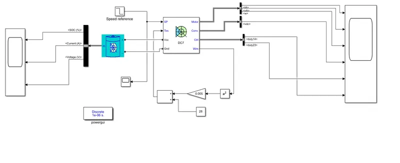
Fig:- Simulink Model for Powertrain using DC7 Block
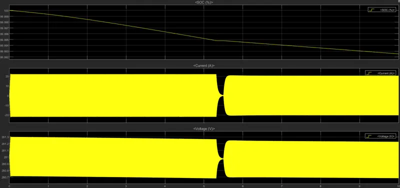
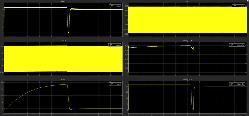
Output:-
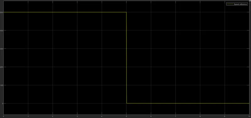
Block diagram of powertrain for Towing Vehicle:-
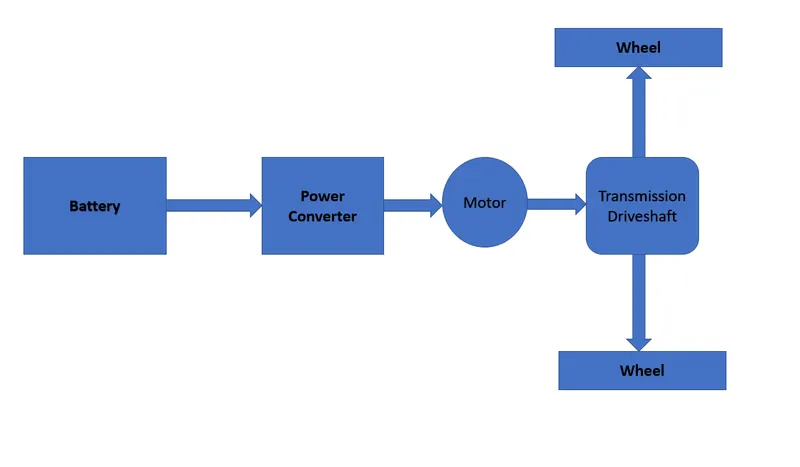
Fig:- Block Daigram of PowerTrain For Towing Vehicle
B. Also, Design the parameters in excel sheet.
Ans:-