Modelling an electric Car with Li-ion battery.
AIM:
Create a MATLAB model of electric car which uses lithium ion battery and suitable motor.
OBJECTIVE:
Develop a MATLAB model of an electric car that utilizes a lithium-ion battery and an appropriate motor. Select the necessary blocks from Simscape or Powertrain block sets and implement a PI controller to regulate the vehicle's speed. Generate brake and accelerator commands without relying on pre-made driver blocks.
To accomplish this objective, we will utilize the capabilities of MATLAB and the Simscape or Powertrain block sets to create a model of an electric car. We will select a suitable lithium-ion battery and motor, and build the necessary components to simulate the behavior of the vehicle.
We will then implement a PI controller to regulate the vehicle's speed, without relying on pre-made driver blocks. This will allow us to generate brake and accelerator commands that are specific to our model and our control system.
Overall, this project will provide a comprehensive understanding of electric car modeling and control, as well as the underlying physics and mathematics of electric vehicles.
Choosing the correct parameters for an electric vehicle and understanding their properties is a crucial first step in developing an effective model. In this project, we will explore the vehicle parameters through the simulation of an electric car using MATLAB/Simulink.
By working within the MATLAB/Simulink environment, we will be able to simulate the behavior of the electric vehicle and observe how it responds to different inputs and scenarios. This will enable us to better understand the characteristics of the vehicle's components and how they interact with one another.
Through this project, we will gain a comprehensive understanding of the importance of selecting appropriate parameters for an electric vehicle and the impact they have on the performance of the vehicle. Additionally, we will develop proficiency in the MATLAB/Simulink environment and its capabilities for simulating and analyzing complex systems.
KEYWORDS:
Electric vehicle, vehicle parameters,simulation, MATLAB/Simulink.
This project focuses on the study of electric vehicles and their parameters through simulation using MATLAB/Simulink. We will examine the characteristics of electric vehicles and their various components in order to better understand their behavior and performance.
The simulation of the electric vehicle within the MATLAB/Simulink environment will allow us to observe and analyze the interactions between the various components of the vehicle. By doing so, we will gain insight into the selection of appropriate parameters for the vehicle, as well as the impact they have on its overall performance.
Throughout this project, we will develop a deeper understanding of electric vehicles and their parameters, as well as become proficient in using MATLAB/Simulink for simulation and analysis.
INTRODUCTION:
In recent times, there has been a growing emphasis on reducing energy consumption and minimizing the environmental impact of transportation. This has led to an increased interest in the electrification of vehicles, as fossil fuel depletion, urban pollution, and the greenhouse effect continue to pose serious concerns globally. While Internal Combustion Engine (ICE) technology has undergone significant advancements over the past century, its primary focus has been on improving fuel economy and reducing emissions.
Electric Vehicles (EV), powered by batteries, have emerged as a promising solution due to their high efficiency, zero emissions, silent operation, and potential for regulation by the power grid operator. However, the adoption of EVs is still hindered by certain battery-related challenges, such as their high initial cost, limited driving range, and long charging time. To accurately estimate and optimize the energy consumption of EVs, it is crucial to develop a model of an EV that considers these challenges.
Having a good model of an EV is essential in avoiding incorrect conclusions and making informed decisions. Through the development of an accurate EV model, we can better understand and address the challenges associated with battery technology, ultimately enabling the widespread adoption of sustainable transportation solutions.
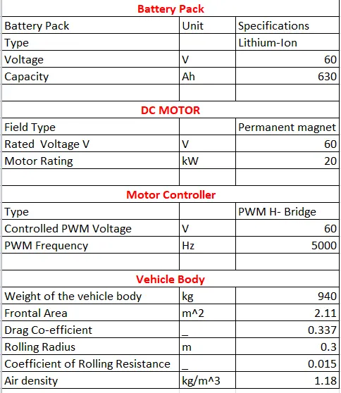
Modelling of EV vehicle:Specifications of Electric vehicle:
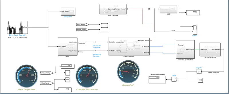
The second subsystem contains the power controller, which takes the desired output voltage from the battery pack and provides controlled PWM voltage output to the motor. This helps to control the speed of the motor and therefore the speed of the vehicle.
The third subsystem contains the battery pack, which provides power to the motor. The battery pack is modelled as a DC voltage source with an internal resistance. The voltage of the battery pack is regulated by the power controller.
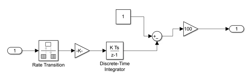
The fourth subsystem contains the SOC (State of Charge) of the battery. It monitors the amount of energy remaining in the battery and displays it as a percentage. The SOC can increase due to regenerative braking.
The fifth subsystem contains the motor and gear system. The DC motor is used to drive the wheels, while the gears are used to change the torque and speed of the motor.
The sixth subsystem contains the vehicle dynamics. It includes the mechanical parts of the system such as tires, vehicle body, transmission (simple) gears, differential, and the motor. The tires and the vehicle body are formed into a subsystem to separate the mechanical components from the electrical components. Physical input ports for wind speed and inclination of the road are connected to the W and beta ports, while physical output ports for the velocity of the vehicle are connected to the V, NF, and NR ports. The front and rear axles are modelled as normal forces, while the H port is used for horizontal motion and is connected to the tie port.
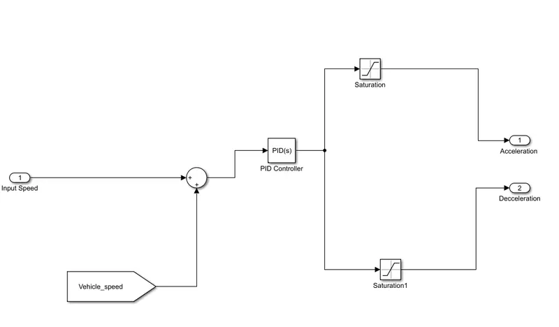
1.Subsystem contains the Driver:
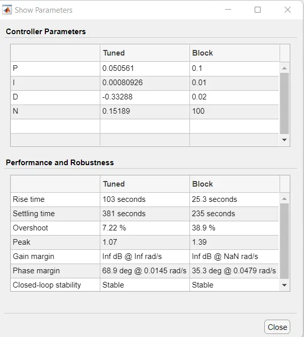
PID Tunning:
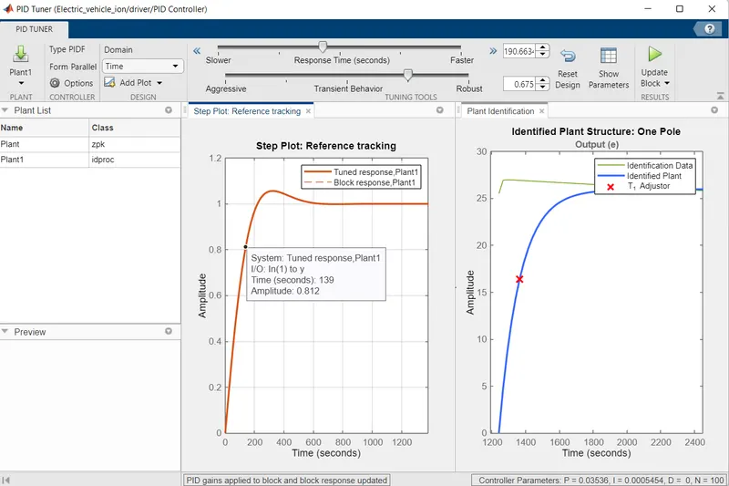
Controller Parameters:
2.Subsystem contains the Power Controller:
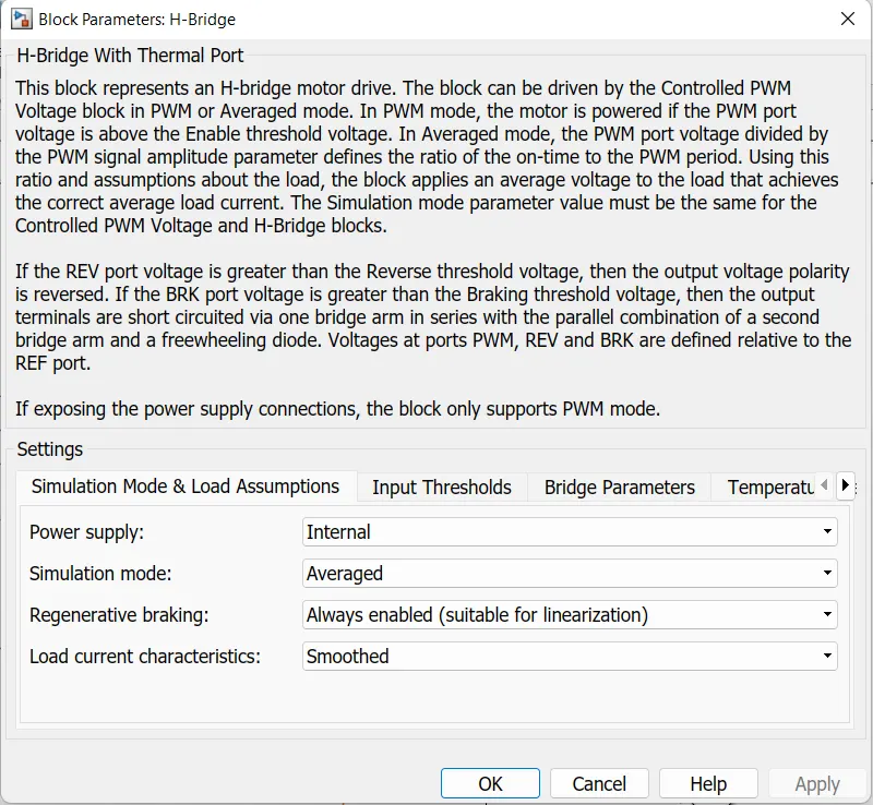
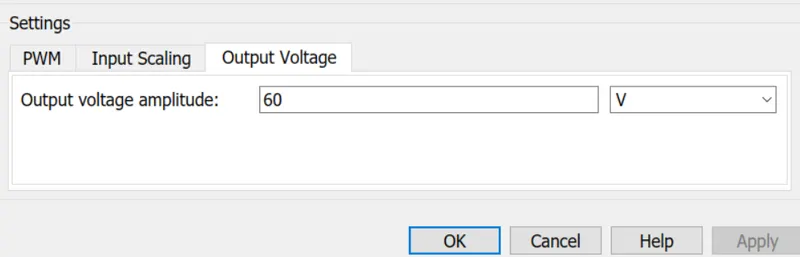
All the systems of the model are dependent of power and it has to be supplied in control. A power controller consists of a sine PWM voltage circuit, H-bridge circuit and a current sensor. The output voltage amplitude is set to 110V for PWM and the same is for H-Bridge.
The image shows of the Motor circuit and controlled subsystem.
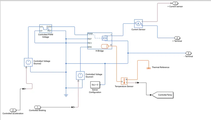
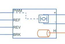
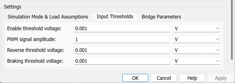
To drive a motor in our electric vehicle model, we use the H-Bridge Motor Driver block from the Powertrain block set in Simulink. This block has two output ports - a positive port and a negative port - that are directly connected to the motor that needs to be controlled. There is also a REV port that enables the reversal of the motor's polarity when the reverse threshold voltage is lower than the REV port voltage. Additionally, the block includes a BRK port that detects the braking condition by comparing its voltage to the breaking threshold voltage. Here, we can see a visual representation of the H-Bridge Motor Driver block.
1) H-Bridge Motor Driver
The H - Bridge with Thermal Port block is used to drive a motor. The H bridge two output ports
Positive Port
Negative Port
This port is directly connected to the motor that has to be controller. There is also a REV port.When the reverse threshold voltage is lower than the REV port voltage,the polariy of the motor is reversed, and if the BRK port voltage is greater than the value of breaking threshold voltage, it indicates that the vehicle is in braking condition.
The following image shows the H-Bridge Motor Driver block from Powertrain block set.
2) Controlled PWM Voltage Source
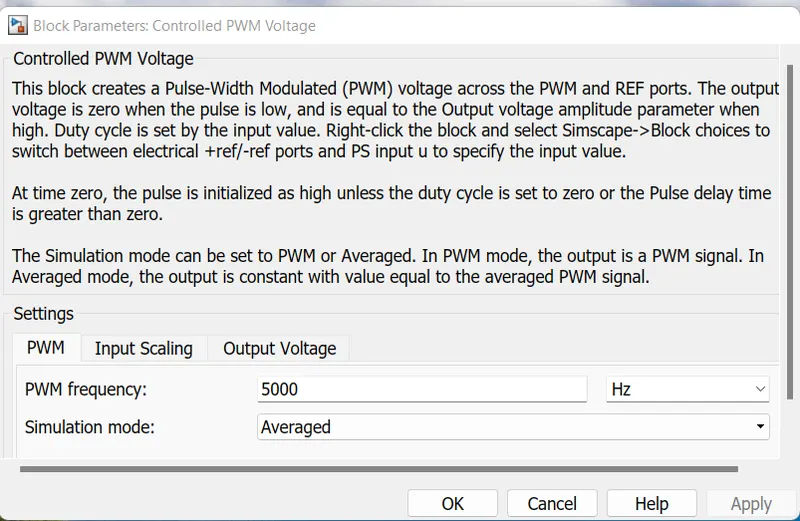
The PWM signal is used or controlling the speed of the traction motor. This block is used for providing a controlled PWM voltage output.
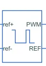
In our electric vehicle model, we use the Controlled PWM Voltage Source block from the Powertrain blockset to control the speed of the traction motor. This block provides a controlled PWM voltage output, which determines the duty cycle of the motor. The duty cycle is calculated using the formula:
100*(Vref - Vmin)/(Vmax - Vmin)
Here, Vref is the reference voltage across the ref+ and ref- ports, while Vmin and Vmax represent the minimum and maximum reference voltages, respectively.
The Controlled PWM Voltage Source block allows us to set the desired reference voltage and control the speed of the motor accordingly. The block can be visualized as shown in the following image.
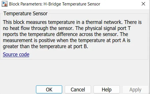
3) Temperature sensor
This block and its parameters are shown below, this block measure temperature in a thermal network. There is no heat flow through the sensor.

4). Current Sensor
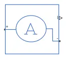
This block is used to measure the flow current through of circuit.
5). Controlled voltage Source
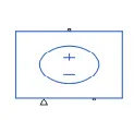
The controlled voltage source block is used to give a constant voltage output. It has two electrical conserving ports and a physical signal port. The output from the controlled voltage source is fed to the controlled PWM voltage source.
3.Subsystem contains the Battery pack
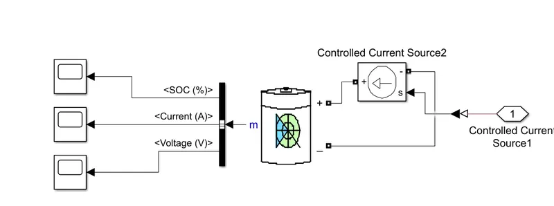
The following image shows the Battery Pack Subsystem
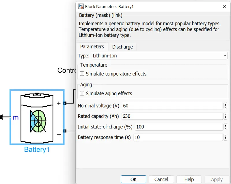
Lithium-ion battery is used for this model with a nominal voltage of 60V. The SOC of the battery reduces as the vehicle starts.
The power controller provides the input cuurent to the battery while charging. The SOC, current and Voltage are the parameters of the battery.
Subsystem Parameters are explained below.
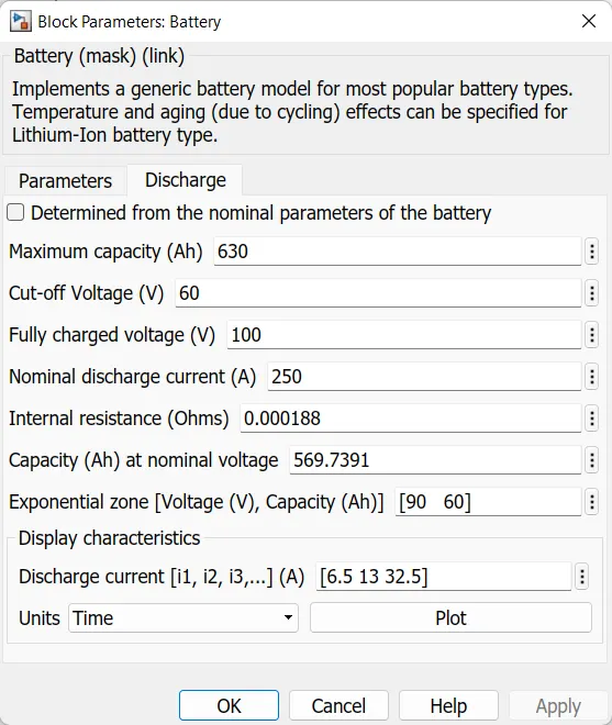
1. Li-ion Battery:
The Battery block implements a generic dynamic model that represent most popular types of rechargeable batteries.
The following image shows the Li-ion Battery block from powertrain blockset.
2) Bus Selector:
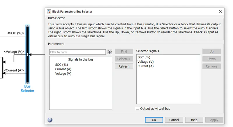
This block accept a bus as input which can be created from Bus creator, Bus selector. from the m port of the battery block , we get SOC,ampere and voltage values. These values are extracted using bus selector , which when connected to the m port , will show those values as shown below,
3) Current Controlled Source:
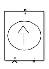
The Controlled Current Source block converts th Simulink input signal into an equvivalent current source The generated current is driven by the input signal of the block.
The following image shows the Current Controlled Source block from Powertrain blockset.
4.Subsystem contains the SOC(State of Charge)
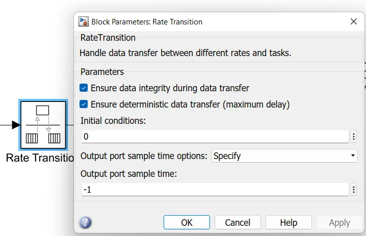
1) Rate transition
Rate transition handles data transfer between different rates and tasks. The SOC of the battery reduces as the vehicle starts and increase when the charger is connected.
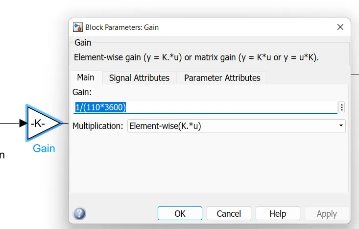
2) Gain
5.Subsystem contains the Motor and Gear System
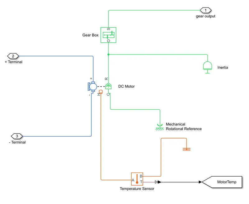
Subsystem Parameters are explained below.
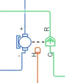
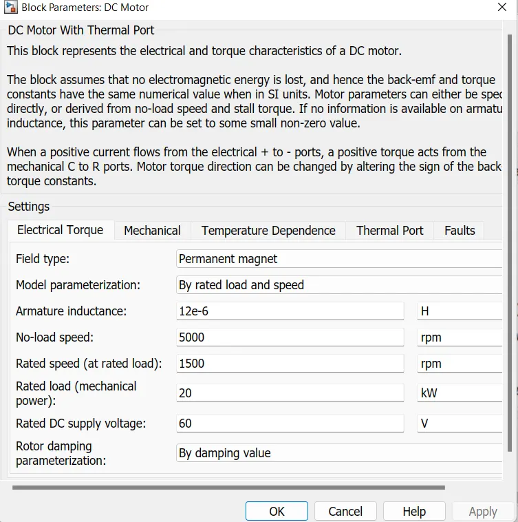
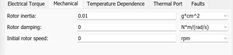
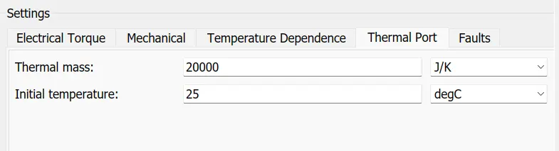
1. DC Motor
The DC motor plays a crucial role in our electric vehicle model, as it is responsible for converting electrical energy from the battery to mechanical energy to drive the wheels. We have selected the DC motor as it is widely used in electric vehicles for its simplicity, efficiency, and easy controllability.
In our model, one end of the DC motor block is connected to the vehicle body blocks, while the other end is connected to the DC motor driver block. The DC motor driver controls and rotates the motor based on the input signals received from the rest of the system.
The DC motor block is shown in the following image, which is taken from the Powertrain blockset.

6.Subsystem contains the Vehicle Dynamics
In the vehicle dynamics subsystem, the model of the vehicle body is presented, which combines both electrical and mechanical parts. The mechanical parts comprise the tires, vehicle body, transmission (simple) gears, differential, and motor. The tires and vehicle body are grouped into a subsystem to separate the mechanical component from the electrical components. The block parameters can be modified based on specific requirements. The image of the subsystem is displayed below.
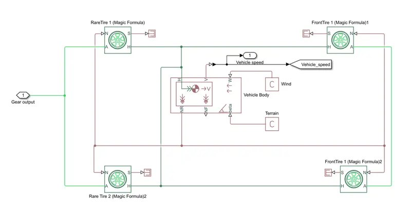
Subsystem blocks are explained below:
1. Vehicle Body:
These is the block of vehicle body which represents a dual axel vehicle or a 4 wheeer. There are 6 ports.
The following image shows the Vehicle body block from Powertrain block set.
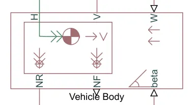
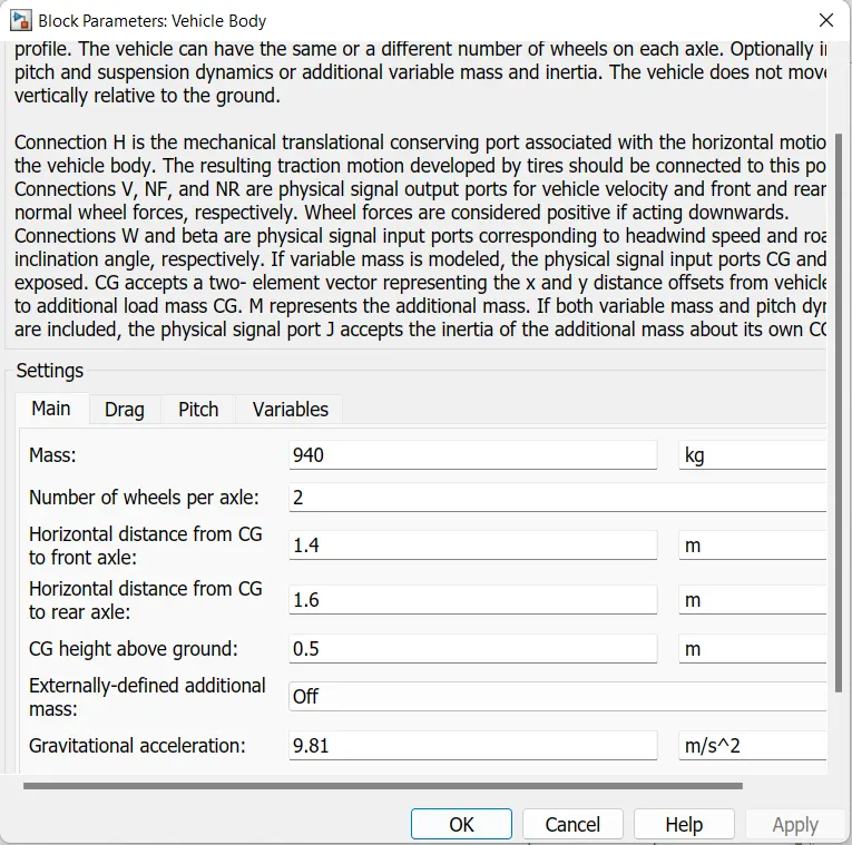
The subsystem has physical signal input ports W and beta, which are used to input wind speed and inclination of the road, respectively. The physical signal output ports V, NF, and NR are used to output the velocity of the vehicle. The Front axel and Rear axel ports represent the normal forces, while the H port represents the horizontal motion. The tie is connected to the H port.
2. Tire (Magic Formula)
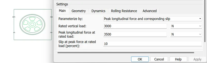
We have selected the tire(Magic Formula).
The following image shows the Tire block from Powertrain block set.
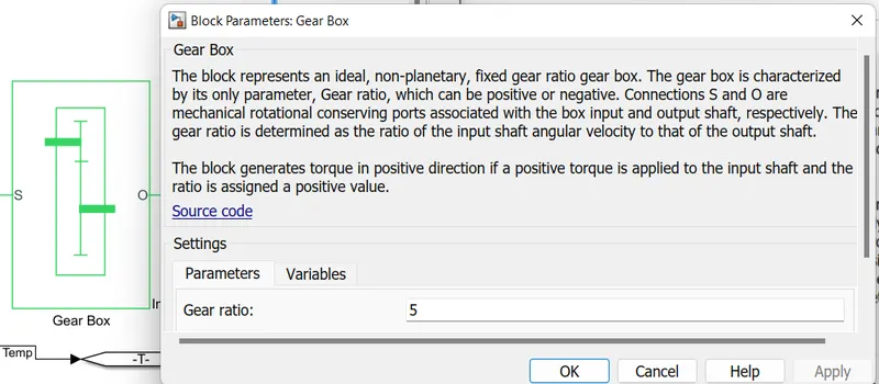
3. Simple Gear:
This block is used for giving a fixed gear ratio. This is a mechanical component and can be avoided, but it ives users the ability to adjust vehicle speed with respect to the rpm of the motor.
The following image shows the Simple gear Powertrain block set.
Drive Input :
The block is capable of taking feedback velocity of the ehicle and changing the speed by giving output signal, it can decide when the vehicle needs to be accelerated and when the break need to be applied.
1. Drive Cycle Source
The Drive cycle source block is used to provide the refernence Speed of the simulation.
The following image shows the Drive Cycle Source block from Powertrain blockset.
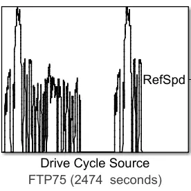
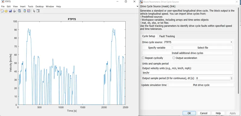
There are many Drive cycle sources as well as we can generate our own signal by using signal builder. So I used the FTP75 Drive Cycle Source block to create the Drive input.
4. Testing and simulation
After designing the circuit, all thet is left is testing the circuit. We usually need to put scope at any point in the circuit to measure the desired parameters. The scope module looks like the one shown below.
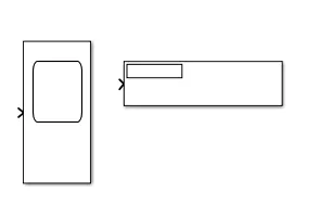
The scope can have multiple inputs, and the real time output is displayed when the simulation.
Results:
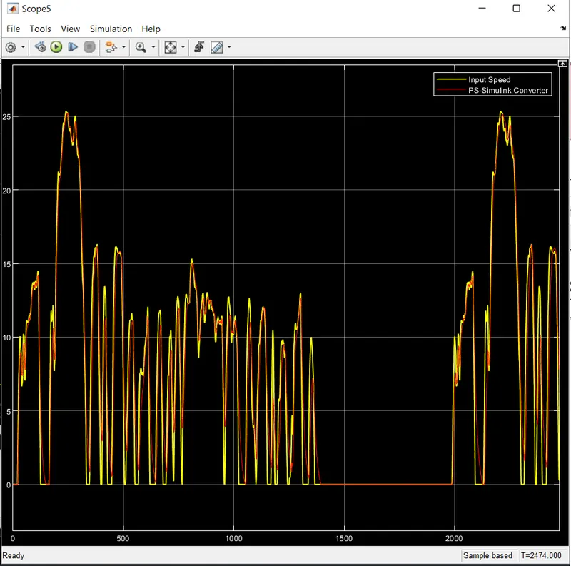
Simulation of the model was carried out using the FTP75 drive cycle. The Drive Cycle source FTP75 was used to input the drive cycle data into the model. The duration of the FTP75 drive cycle is 2474 seconds.
1. Distance travelled
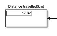
The distance travelled by the vehicle is 17.82km
SOC:
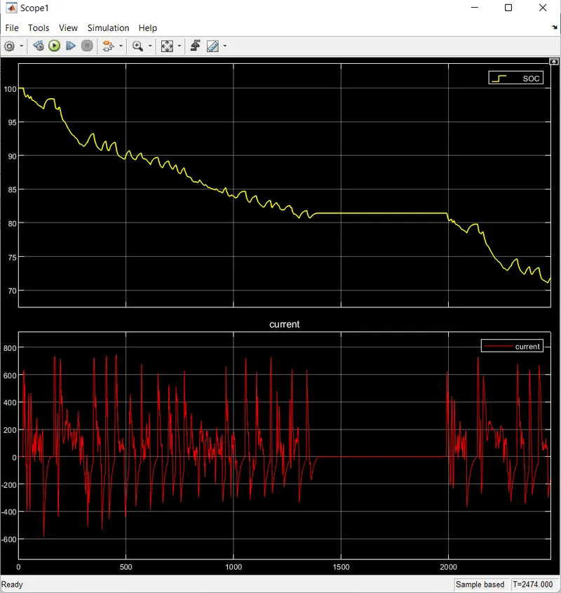
The SOC percentage graph shows that after running for 2474 seconds, the battery's SOC has fluctuated from 100% to approximately 72%. During this time, the vehicle has traveled for 17.82 Km. While the overall trend of SOC is decreasing, there are instances where it increases, mainly due to regenerative braking.
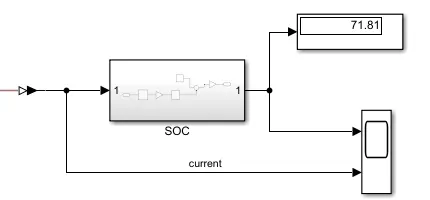
The SOC is dropped from 100% to (approx)72%.
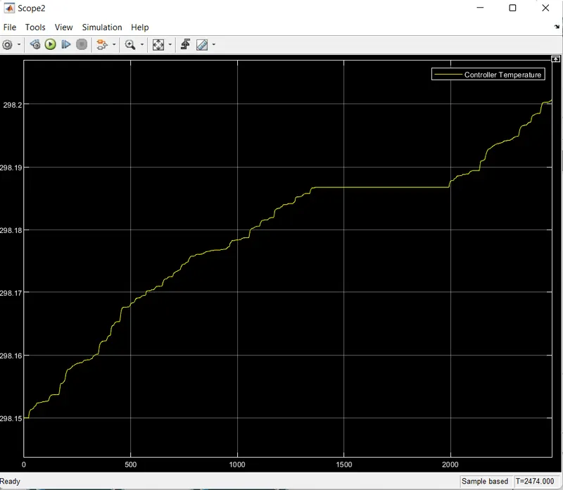
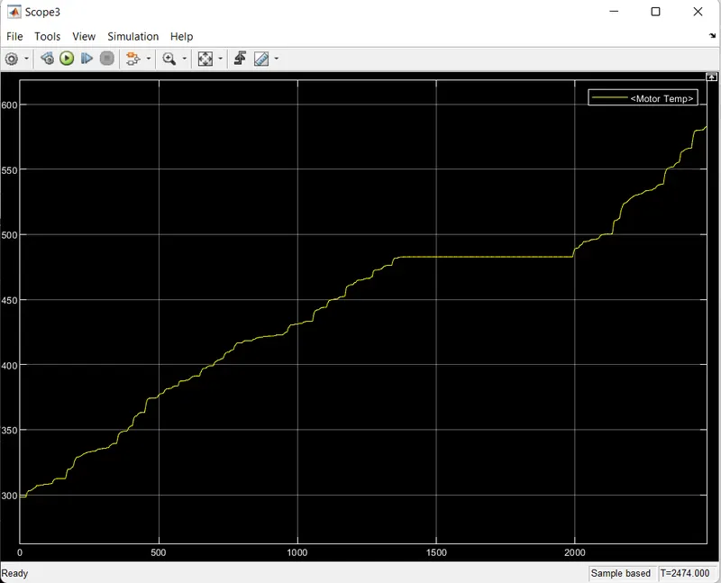
Temperature:
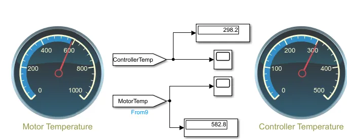
Controller Temperature:
Motor Temperature:
In conclusion, a Matlab model of an Electric Vehicle was created using appropriate blocks from the powertrain block set. The design process involved the creation of subsystems for the driver, power controller, battery pack, state of charge, motor and gear system, and vehicle dynamics. The model was then tested with the FTP75 drive cycle, which resulted in the vehicle traveling 17.82Km with a simulation time of 2474 secs. The state of charge of the vehicle's battery intermittently decreased from 100% to approximately 72%, with some periods of increase due to regenerative braking. Overall, the designed Electric Vehicle model successfully demonstrated its ability to function in a simulated environment.