Project-1: Modelling an electric Car with Li-ion battery
AIM : To model an Electric car with Lithium-ion battery.
THEORY :
An electric vehicle (EV) is one that operates on an electric motor, instead of an internal-combustion engine that generates power by burning a mix of fuel and gases. Electric vehicles have low running costs as they have less moving parts for maintaining and also very environmentally friendly as they use little or no fossil fuels (petrol or diesel). While some EVs used lead acid or nickel metal hydride batteries, the standard for modern battery electric vehicles is now considered to be lithium ion batteries.
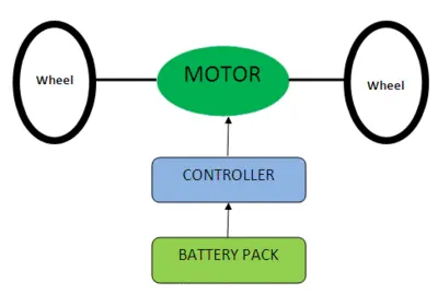
Figure shows a basic EV block diagram parts. Battery, Controller and Motor are main parts of an vehicle.
SOLUTION :
The EV vehicle model is designed in Matlab -Simulink which is as below:
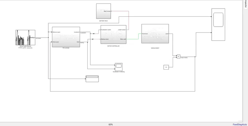
The following is description for above model:
i. Drive cycle:
A driving cycle is a series of data points representing the speed of a vehicle versus time. Driving cycles are produced by different countries and organizations to assess the performance of vehicles in various ways, as for instance fuel consumption, electric vehicle autonomy and polluting emissions.
Another use for driving cycles is in vehicle simulations. More specifically, they are used in propulsion system simulations to predict performance of internal combustion engines, transmissions, electric drive systems, batteries, fuel cell systems, and similar components.
Drive cycle block generates the standard longitudinal drive cycle which can be used for simulation. It is used to predict engine torque and fuel consumption that a vehicle requires to achieve desired speed and acceleration for a given gear shift reference. It gives braking commands for vehicle models.
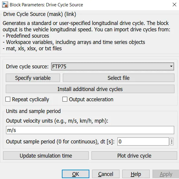
In this model we used standard FTP75 drive cycle
Its plot is as below:
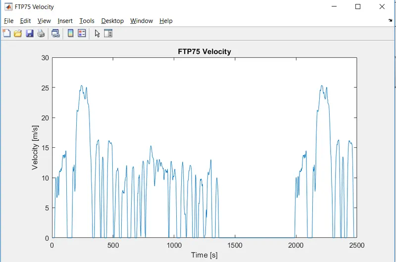
From this drive cycle the maximum velocity is 25m/sec.
ii. Driver control:
Instead of using longitudinal driver block, we are generating the acceleration and brake commands using PID controllers. The subsystem for Driver control block is as below:
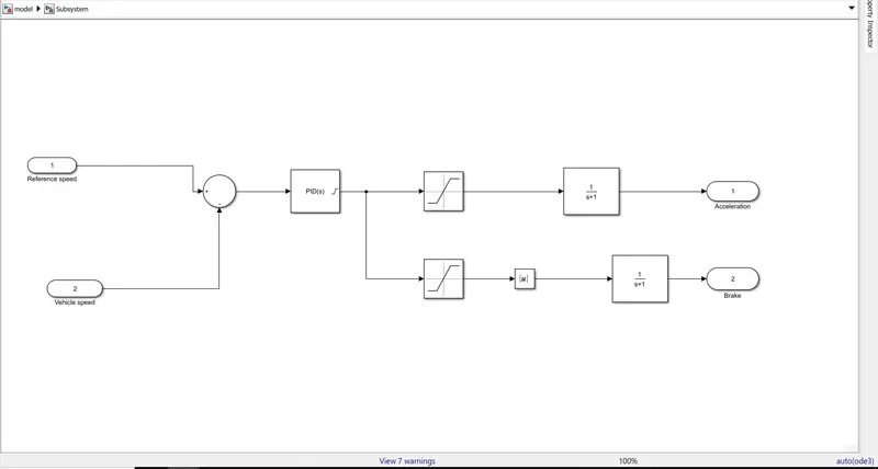
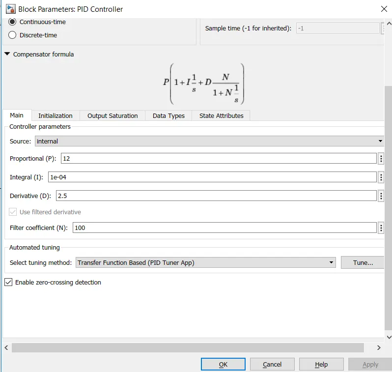
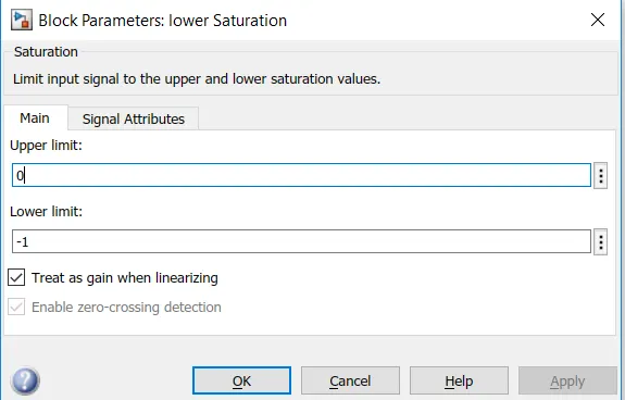
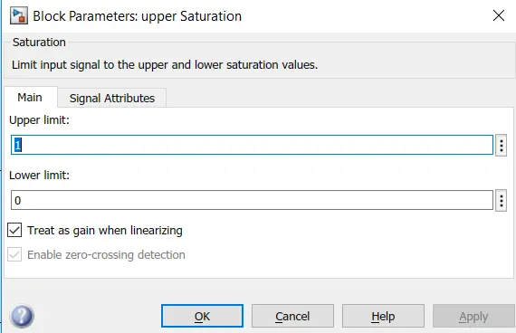
Driver control block is main controller for vehicle for giving accelerating and brake commands. This is a closed loop control in which reference speed is taken as input and compares with vehicle speed which can reduces the error. By using saturation block the upper and lower limits of acceleration and decelaration commands are limited in PID controller.
iii. Motor and Controller:
Motor and controller is designed inside the subsystem as follows:
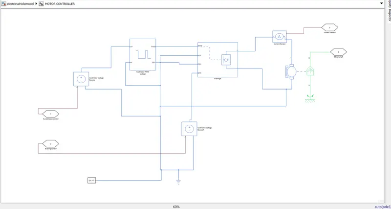
The following decription gives clear idea about all the parts inside the subsystem.
i. Motor: Permanent Magent Brushed type motor should be used. This block represents the electrical and torque characteristics of a DC motor. The block assumes that no electromagnetic energy is lost, and hence the back-emf and torque constants have the same numerical value when in SI units. Motor parameters can either be specified directly, or derived from no-load speed and stall torque. If no information is available on armature inductance, this parameter can be set to some small non-zero value. When a positive current flows from the electrical + to - ports, a positive torque acts from the mechanical C to R ports. Motor torque direction can be changed by altering the sign of the back-emf or torque constants.
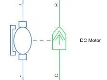
Armature Inductance = 12e-6
No-load speed = 3000 RPM
Rated speed = 1500 RPM
H-Bridge:
This block represents an H-bridge motor drive. The block can be driven by the Controlled PWM Voltage block in PWM or Averaged mode. In PWM mode, the motor is powered if the PWM port voltage is above the Enable threshold voltage. In Averaged mode, the PWM port voltage divided by the PWM signal amplitude parameter defines the ratio of the on-time to the PWM period. Using this ratio and assumptions about the load, the block applies an average voltage to the load that achieves the correct average load current. The Simulation mode parameter value must be the same for the Controlled PWM Voltage and H-Bridge blocks.
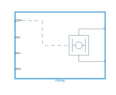
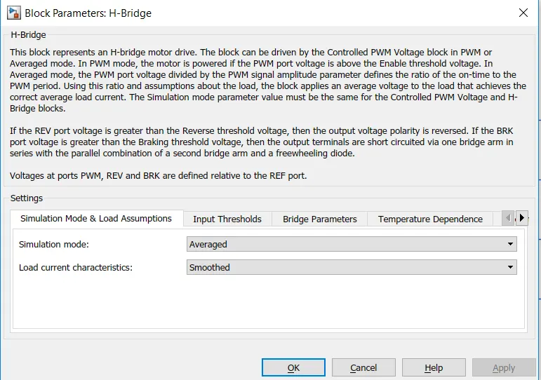
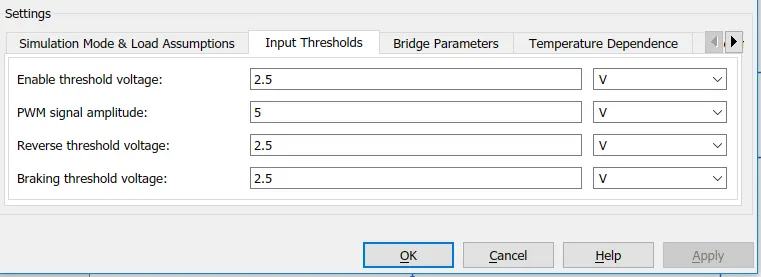
If the REV port voltage is greater than the Reverse threshold voltage, then the output voltage polarity is reversed. If the BRK port voltage is greater than the Braking threshold voltage, then the output terminals are short circuited via one bridge arm in series with the parallel combination of a second bridge arm and a freewheeling diode. Voltages at ports PWM, REV and BRK are defined relative to the REF port.
Controlled Voltage (PWM):
This block creates a Pulse-Width Modulated (PWM) voltage across the PWM and REF ports. The output voltage is zero when the pulse is low, and is equal to the Output voltage amplitude parameter when high. Duty cycle is set by the input value. Right-click the block and select Simscape->Block choices to switch between electrical +ref/-ref ports and PS input u to specify the input value.
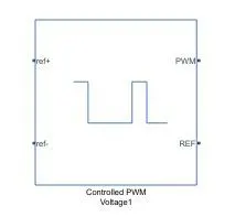
At time zero, the pulse is initialized as high unless the duty cycle is set to zero or the Pulse delay time is greater than zero. The Simulation mode can be set to PWM or Averaged. In PWM mode, the output is a PWM signal. In Averaged mode, the output is constant with value equal to the averaged PWM signal.
Controlled voltage source and Current sensor:
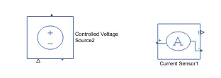
Controlled Voltage Source block represents an ideal voltage source that is powerful enough to maintain the specified voltage at its output regardless of the current passing through it. The output voltage is V = Vs, where Vs is the numerical value presented at the physical signal port.
The Current Sensor block represents an ideal current sensor, that is, a device that converts current measured in any electrical branch into a physical signal proportional to the current.
iv. Battery:
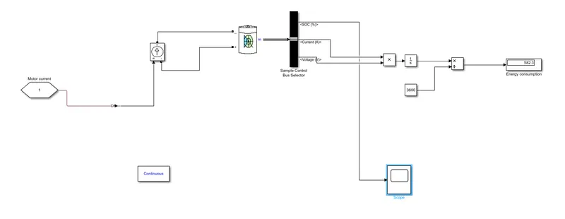
This block models a battery. If you select Infinite for the Battery charge capacity parameter, the block models the battery as a series internal resistance and a constant voltage source. If you select Finite for the Battery charge capacity parameter, the block models the battery as a series internal resistance plus a charge-dependent voltage source defined by:
V = Vnom*SOC/(1-beta*(1-SOC))
where SOC is the state of charge and Vnom is the nominal voltage. Coefficient beta is calculated to satisfy a user-defined data point [AH1,V1]
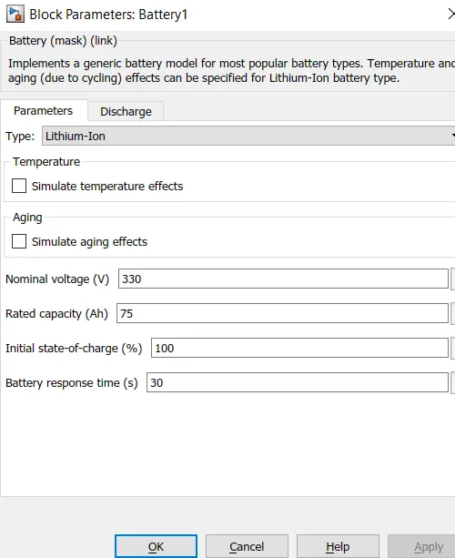
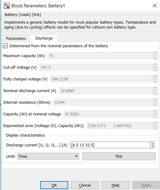
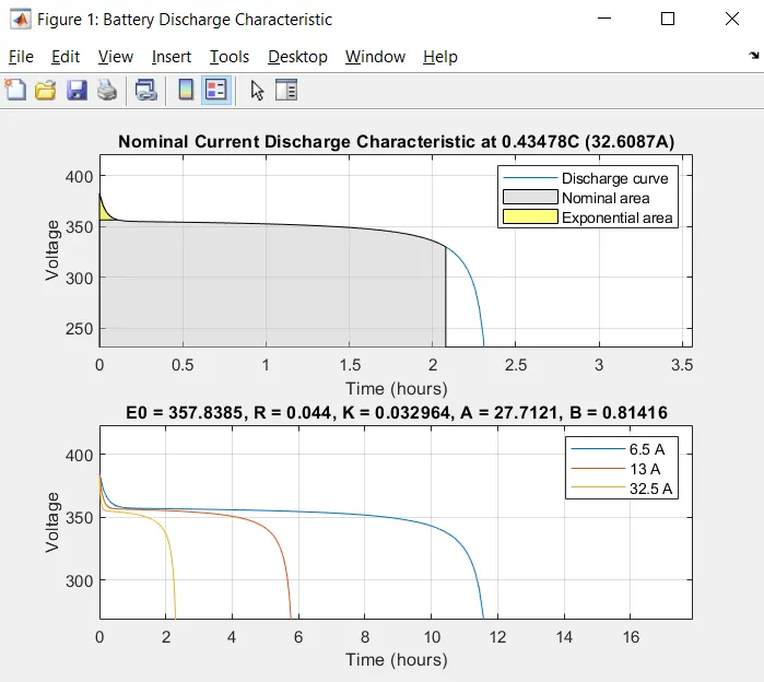
Lithiumion battery is used in this problem, and the parameters are:
v. Vehicle Body
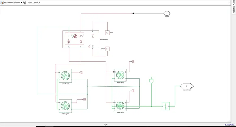
The whole vehicle body parts are in subsystem as below:
Tyre:
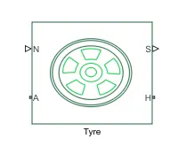
Tire represents the longitudinal behavior of a highway tire characterized by the tire Magic Formula. The block is built from Tire-Road Interaction (Magic Formula) and Simscape Foundation Library Wheel and Axle blocks. Optionally, the effects of tire inertia, stiffness, and damping can be included.
Connection A is the mechanical rotational conserving port for the wheel axle. Connection H is the mechanical translational conserving port for the wheel hub through which the thrust developed by the tire is applied to the vehicle. Connection N is a physical signal input port that applies the normal force acting on the tire. The force is considered positive if it acts downwards. Connection S is a physical signal output port that reports the tire slip. Optionally expose physical signal port M by setting Parameterize by to Physical signal Magic Formula coefficients. Physical signal port M accepts a four element vector corresponding to the B, C, D, and E Magic Formula coefficients.
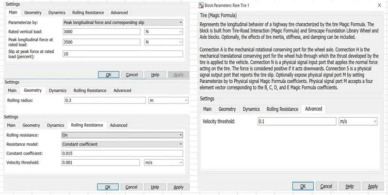
The following are the different parameter values we can fix as we need for tire block
Vehicle body:
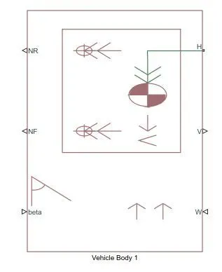
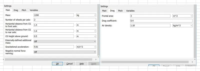
Represents a two-axle vehicle body in longitudinal motion. The block accounts for body mass, aerodynamic drag, road incline, and weight distribution between axles due to acceleration and road profile. The vehicle can have the same or a different number of wheels on each axle. Optionally include pitch and suspension dynamics or additional variable mass and inertia. The vehicle does not move vertically relative to the ground.
Connection H is the mechanical translational conserving port associated with the horizontal motion of the vehicle body. The resulting traction motion developed by tires should be connected to this port. Connections V, NF, and NR are physical signal output ports for vehicle velocity and front and rear normal wheel forces, respectively. Wheel forces are considered positive if acting downwards. Connections W and beta are physical signal input ports corresponding to headwind speed and road inclination angle, respectively. If variable mass is modeled, the physical signal input ports CG and M are exposed. CG accepts a two- element vector representing the x and y distance offsets from vehicle CG to additional load mass CG. M represents the additional mass. If both variable mass and pitch dynamics are included, the physical signal port J accepts the inertia of the additional mass about its own CG.
Inertia:
As the motor is rotating part we have to represent the inertia for rotating shaft. The block represents an ideal mechanical rotational inertia. The block has one mechanical rotational conserving port. The block positive direction is from its port to the reference point. This means that the inertia torque is positive if the inertia is accelerated in the positive direction.

Simple Gear:
Represents a fixed-ratio gear or gear box. No inertia or compliance is modeled in this block. You can optionally include gear meshing and viscous bearing losses.
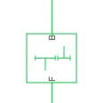
Connections B (base) and F (follower) are mechanical rotational conserving ports. Specify the relation between base and follower rotation directions with the Output shaft rotates parameter. Optionally include thermal effects and expose thermal conserving port H by right-clicking on the block and selecting Simscape block choices to switch between variants.
SIMULATION RESULTS :
The output velocity is compared with the input speed to know the difference between them in the plot. As for the standard drive cycle FTP75 the total simulation time is 2474 seconds.
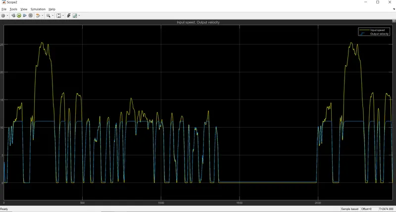
From the plot we can see that output is following input drive cycle so the model is correct
As we are giving the acceleration and brake commands its plot is as below:
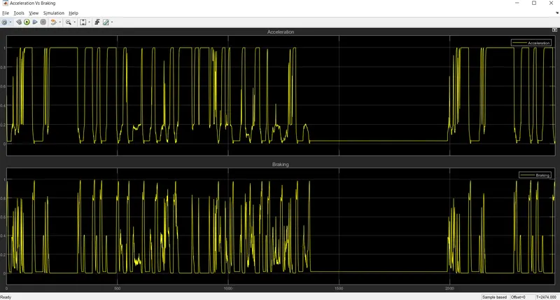
From the plot we can see that the acceleration and brake commands plot is opposite to each other i.e when acceleration is high, brake is low. So we can confirm that the acceleration and brake commands are given correctly as per the given drive cycle.
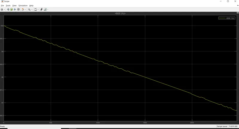
The State of Charge for the Lithium-ion battery is also plotted which is around 96.7 %
CONCLUSION : An Electric car with Lithium-ion battery is designed as per the specifications and the simulink file is attached for reference.