Week - 4
AIM: We have 2 problems to implement in Simulink stateflow to do:
- Implement control logic of a “washing machine” using Stateflow as per given sequence:
- If the power supply is available, the system gets activated
- If the Water supply is not available, stop the process & indicate through LED
- Soaking time should be 200s followed by Washing time of 100s.
- Then rinsing happens for next 20s & dryer runs for 50s
After all the processes have completed turn on the finished LED
2. Make a Simulink chart for the “Gear shift” logic as per below conditions:
Speed Range(kmph) Gear
0 to 15 1
16 to 25 2
26 to 40 3
41 to 60 4
Above 61 5
Give speed input while the simulation is running & display the gear number.
1-Ans). In 1st problem we have to implement the washing machine using stateflow.
Generally, washing machines are used to wash the clothes. There are different types of them like as follows:
a. Fully automated washing machine: After loading the clothes in machine, by switching on the supply the machine works automatically according to the program predefined. There are many programs predefined in the machine while manufacturing, we can select the required program while using. Even drying also made by machine itself.
b. Semi automated washing machine: These are partially automated that means we have to transfer clothes after washing to the dryer drum for drying. This have to be done manually.
Even, we have top load and front load machines, in the market with different uses.
Lets build a simulink model for a Washing machine which is automated fully with time because, in general all fully automated machines are programmed with time delays.
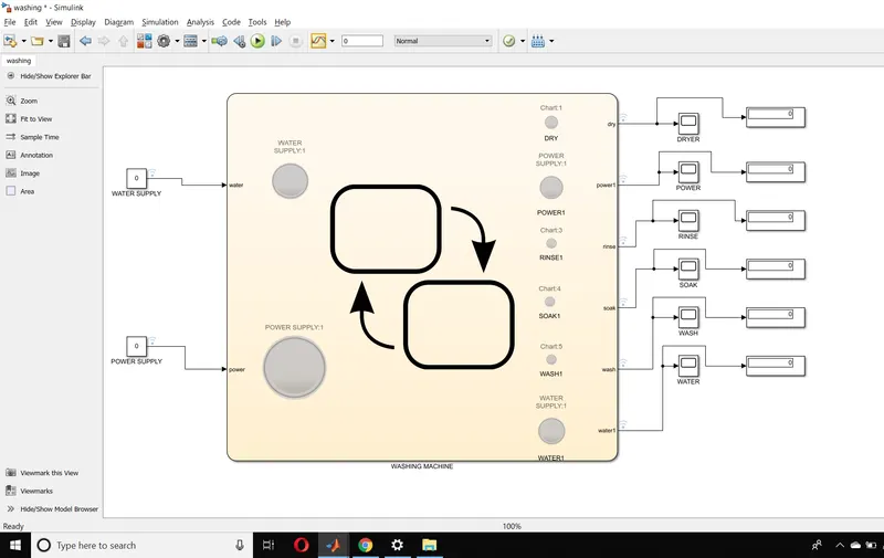
By using the given data i have implemented the below model in simulink-stateflow:
The flow chart we have implemented for the washing machine chart is as below:
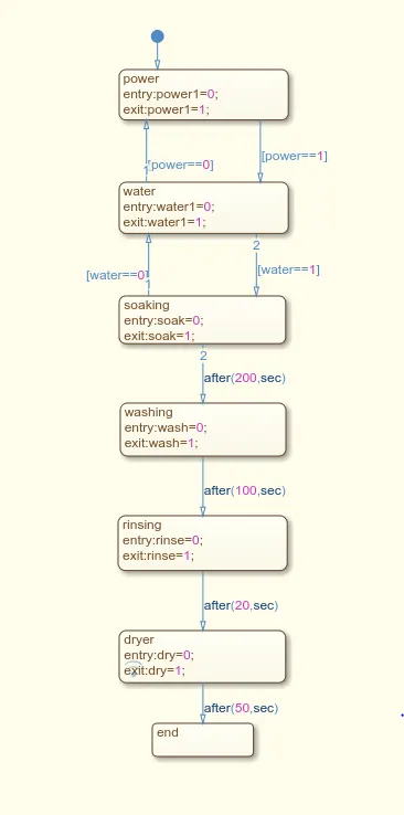
This flow chart is built according to the process of washing machine working i.e., Whenever Water and Power supply are given to the machine, after loading of clothes.The machine will start working according the program we made.
i. In First state, Power supply is received by the machine.
ii. In Second state, Water will be taken by the machine from supply.
iii. In Third state, the clothes are soaked in the water (soaking time is 200sec).
iv. In Fourth state, the clothes are washed (washing time is 100sec).
v. In Fifth state, the clothes are rinsed (rinsing time is 20sec).
vi. In Sixth state, the clothes are dried (drying time is 50sec).
vii. Last, after drying machine is stopped.
From the above the total time is 370sec.
The above model shows the washing machine with lamps to indicate whether the step is completed or not at particular time. It also has displays to indicate the output status, constants to give supply to the machine.
The following are different cases at which the machine is checked at various time periods.
(Consider a.) Green is On for all lamps i.e supply is on at input side and at output side work is completed.
b.) Red is Off for all lamps i.e supply is Off at input side and at output side work is not completed.
c.) Blue is to indicate water and power at output side whether they are On or Off).
i. When Power =1 ; Water =1; At time 150 Sec
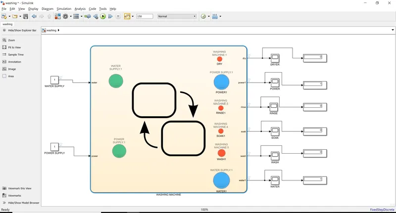
We can see, no didn't get any output becoz only inputs are given to m/c, but the soak will completed at 200th sec
So the output at soak is red i.e no output.
ii. When Power = 1; Water = 1; T= 202sec
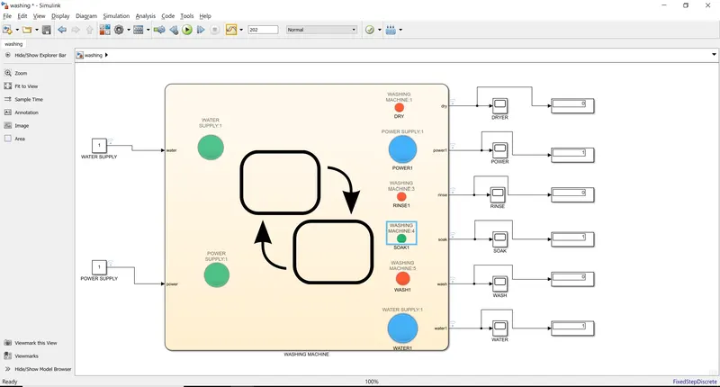
Now after 200 sec the output is shown for soak (Green) as it is completed.
iii. When Power = 1; Water = 1; Time = 302sec
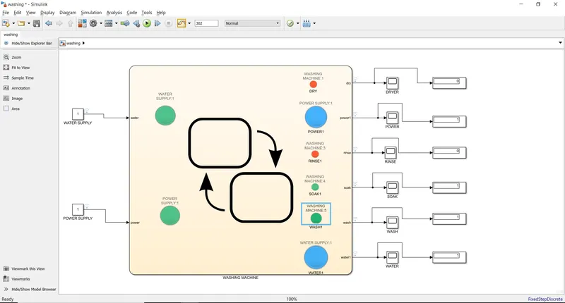
Here. both soak. wash are completed.
iv. Power = 1; Water = 1; Time = 322sec
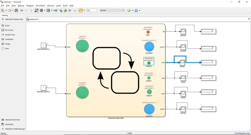
In this three states are completed i.e., Soak, Wash, Rinse.
v. Power = 1; Water = 1; Time= 372sec
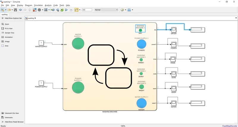
After the total time cycle of 370Sec all the outputs are completed.
vi. Water =0 ; Power = 1; Time = 371sec
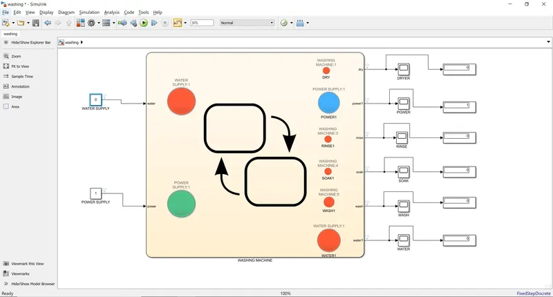
Here, even if Power supply is given without giving Water supply after total Cycle time also the work is not completed. So all lamps are in red color.
This is the brief explanation of the Washing maching stateflow problem.
2-Ans.) Gear shifting mechanism is to be implemented in this.
The following is the model built in Simulink stateflow :
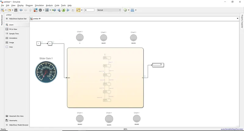
The flow chart for the above model is as below:
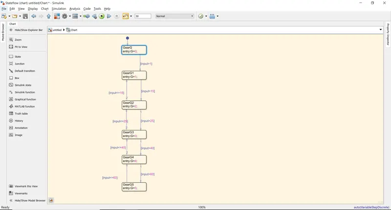
We have used lamps to indicate the output of which gear is used i.e by different speed ranges:
i. For speed of S= 0 to 15 kmph the gear should be 1.
let take S=12kmph. The output is
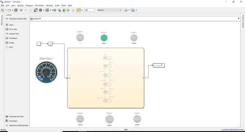
Gear 1 is selected.
ii. For speed of S= 0 kmph the gear should be nothing.
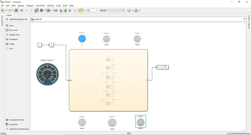
Here as s=0; no gear is selected i.e., 0 for blue led.
So this is how, the given problems are implemented in Stateflow.