Project
AIM: To carry out the system level simulation of All-Terrain vehicle ( Baja-All-Terrain-Vehicle-ATV model) and to prepare a technical report on it.
INTRODUCTION:
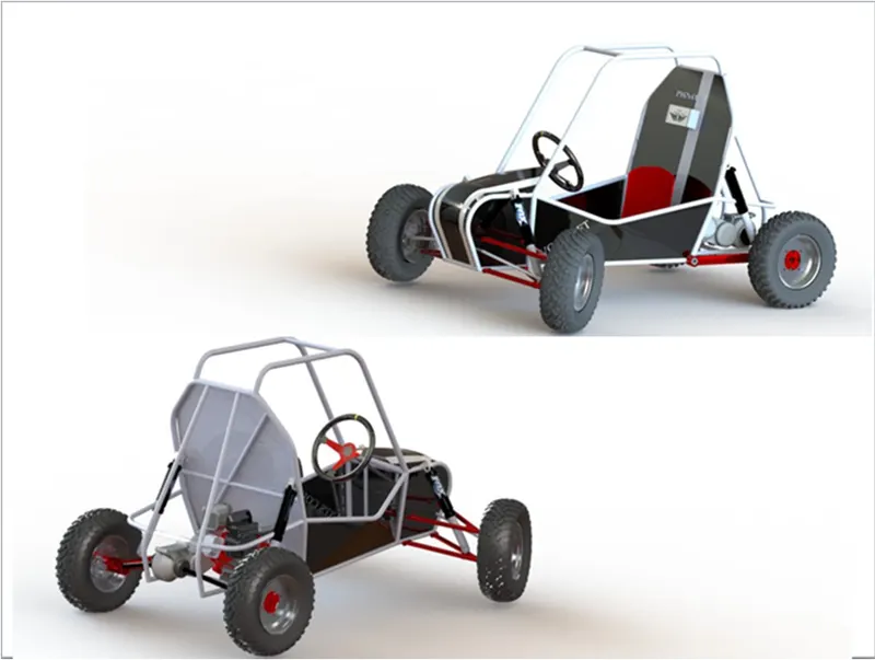
ATV means All-Terrain Vechicle designed to travel on all types of ground including rough ground. ATV is defined as vehicle with a straddle seating position, handlebar steering and ability to travel in all terrain conditions.
The rider sits on operates same as bike but due to extra wheel stability is more in these type vehicles. According to American National Standards Institute (ANSI) this vehicle is designed to handle all variety of terrain than most other vehicles. ATV's are also called as Quadricycle, Threewheeler cycle, Fourwheeler cycle.
MAIN PARTS:
1. CONTINUOUSLY VARIABLE TRANSMISSION (CVT):
A CVT changes through unending range of effective gear ratios while you driving but other kinds of transmissions offer fixed number of gear ratios. CVT systems are also called as single-speed, shiftless, stepless transmissions.
Due to shiftless nature of CVT offers unparalleled flexibility that maintains constant angular velocity. CVT's are used in automobiles, earth moving equipment etc. The most common type of CVT uses two pulleys connected by a belt or chain. CVT also makes accelerating smooth and offers enhanced fuel economy.
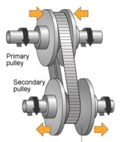
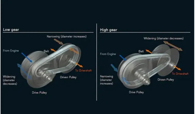
CVT system consists of cones at each pulley connected via chain belt. The cones can move to increase or decrease the belt diameter to change the gear ratios. One pulley in CVT is connected to the engine and other directs power to wheels. Width of pulleys changes based on the needed power as one gets larger and other gets smaller.
CVT BLOCK -
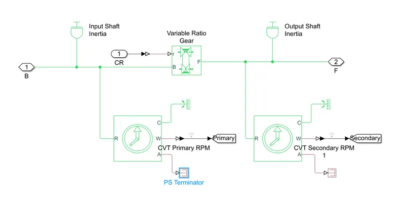
a) Variable Ratio Gear: It represents a variable ratio gearbox implemented by mechanical belt CVT, electric, or hydraulic transmissions. The physical signal input r defines the ratio of input to output angular shaft velocities. Connections B(base) anf F(follower) are mechanical rotational conserving ports. Specify the relation between base and follower rotation directions with the output shaft rotates parameter.
b) Ideal Rotational Motion Sensor: A device converts an across variable measured between two mechanical rotational nodes into a control signal proportional to angular velocity. The sensor is ideal since it does not account for inertia, friction, delays. Connnections R and C are mechanical rotational conserving ports and connection W and A are physical signal output ports for velocity and angular displacement.
c) PS Terminator: Used to terminate physical signal outputs. Unconnected physical signal output ports don't generate warnings, but connection to a PS terminator can be used to indicate signal was not left unconnected.
d) Inertia blocks: Inertia blocks are connected to ensure the proper inertial motion.
2. ENGINE :
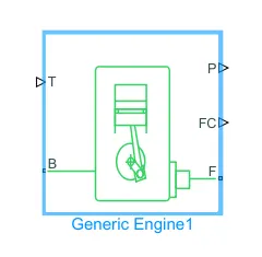
A basic engine represents spark ignition and diesel engines suitable for use at initial stages of modeling when only the basic parameters are available. Throttle(T) input signal lies between zero and one, specifies the torque demanded from the engine as a fraction of the maximum possible torque. If engine speed falls below stall speed, torque is blended to zero. If the speed exceeds maximum speed, simulation stops and issues an error message.
Connections F,B are mechanical rotational conserving ports associated with engine crankshaft and engine block. Connections P, FC are physical signal output ports through which engine power and fuel consumption rate are reported.
3. SIGNAL BUILDER :
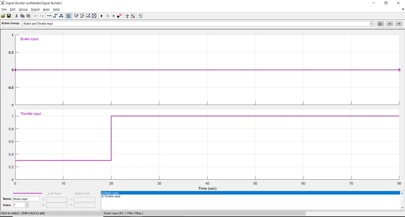
Signal Builder is used to create signals for brake and throttle .
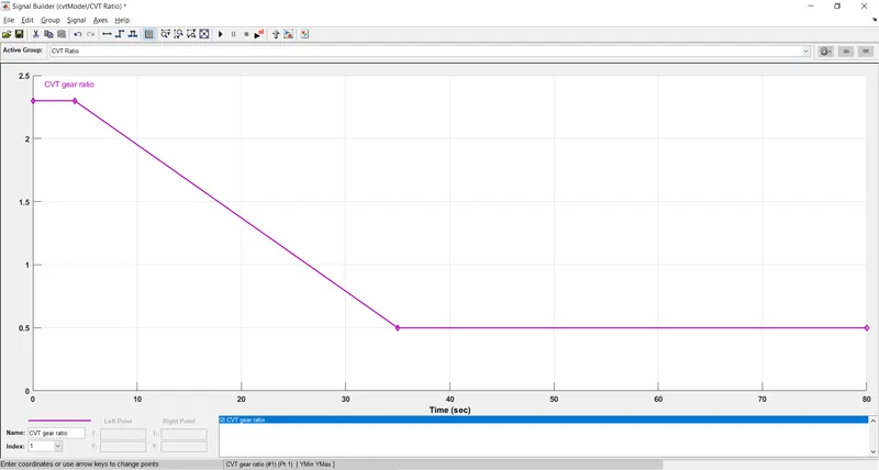
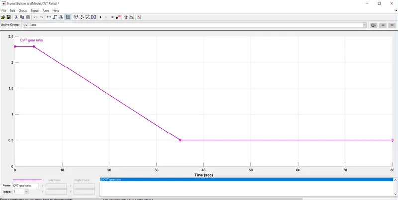
CVT gear ratio input is given from signal builder as below:
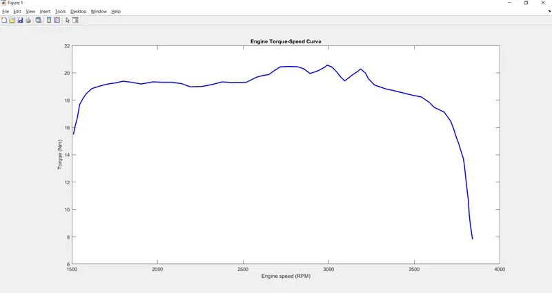
Engine Torque - Speed curve
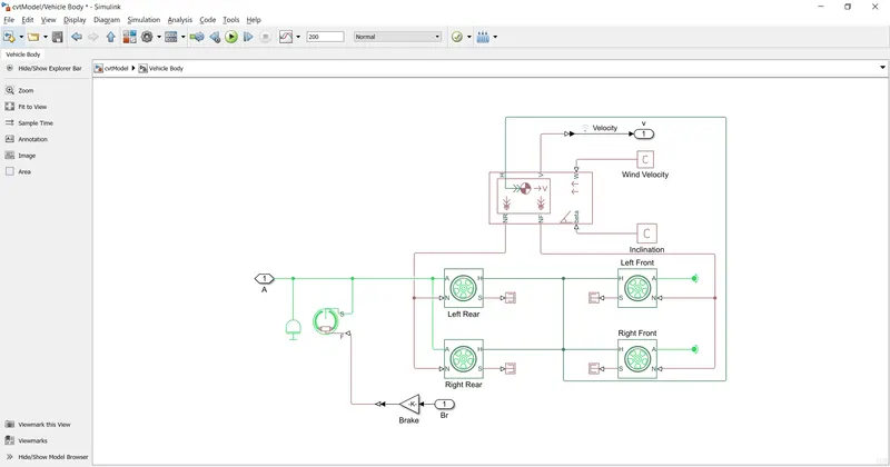
4. VEHICLE BODY:
OUTPUT :
1. CVT MODEL:
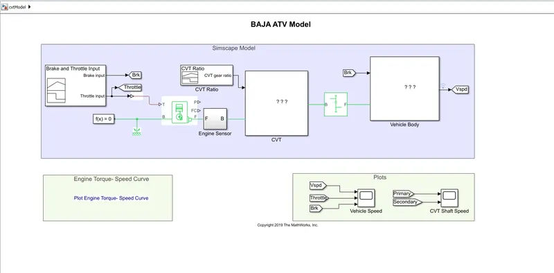
i. In this model the input values- Brake is value is kept as 0 and Throttle input is given a rise at t=20sec with help of Signal builder as below :
ii. Input CVT ratio is given with help of another signal builder block. Its value is constant for 2.3 for 4 sec and then reduced linearly to 1.8 at 35 sec as below:
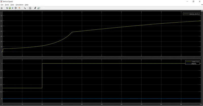
Output for CVT model :
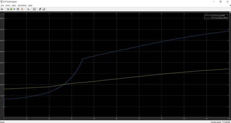
i. Output velocity is shown in plot where at starting sudden raise occured at throttle of 0.3, and then it is constant for next 20sec. Vehicle speed increased gradually until full throttle push and continued to accelerate until it reaches full speed.
ii. CVT shaft speed are as below:
2. CVT MODEL DASHBOARD:
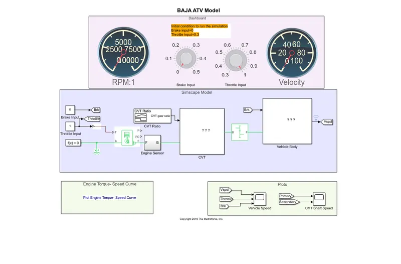
The difference between previous model and this there is knob instead of signal builder, to make real time simulation it will be useful, where is input is varied while simulation is running.
Output:
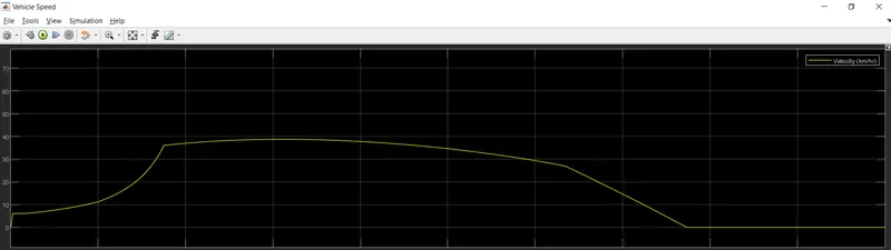
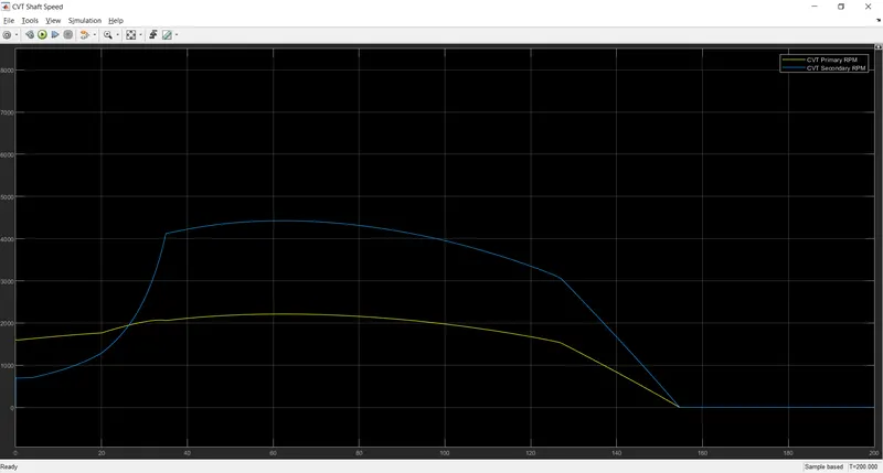
Now throttle is maintained at 0.3 after 80 sec the brake is applied, so velocity becomes 0 after 80 sec means vehicle stops.
CONCLUSION :
A system level simulation is performed while keeping the throttle input constant. Brake is applied at 80 sec so after 80 sec the vehicle slowed down accordingly velocity became zero.