Project 1 (Mini Project on Vehicle Direction Detection
EMD BATCH 08
Project 1 (Mini Project on Vehicle Direction Detection)
Objective of Mini Project:
1. Development of MATLAB Simulink model as per requirement.
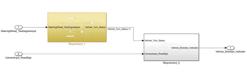
- Below is shown our main subsystem which is based on two given requirements. This main subsystem consists of two inputs and one output.
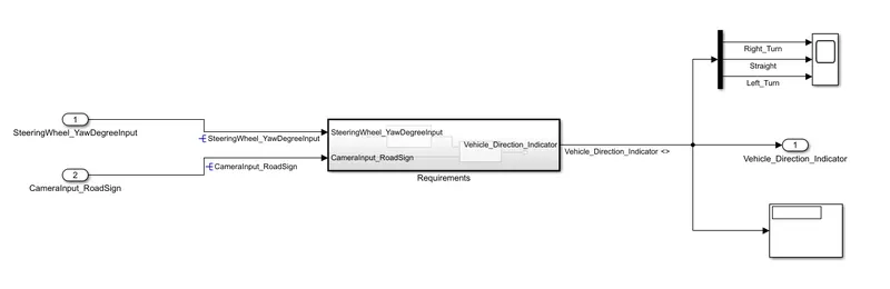
- Inputs are: SteeringWheel_YawDegreeInput and CameraInput_RoadSign and Output is: Vehicle_Direction_Indicator
- Each of the inputs has separate Subsystems shown below.
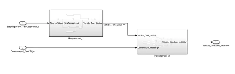
- For input SteeringWheel_YawDegreeInput model is designed based on Requirement-1 using blocks of Constant and switch. It has output as Vehicle_Turn_Status which is fed into the input of a second subsystem based on Requirement-2 which is designed using blocks of Constant, Relational operator and Logical operator.
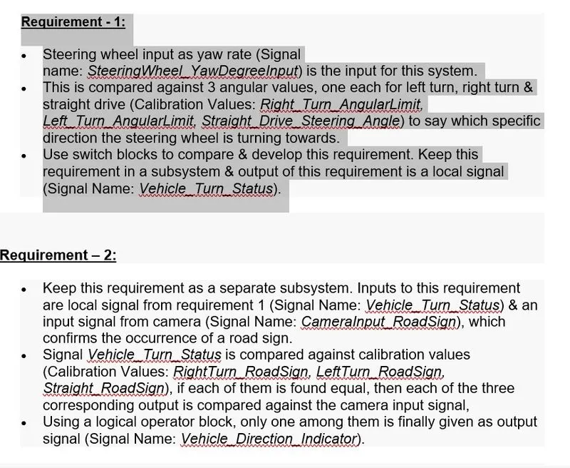
Requirement-1
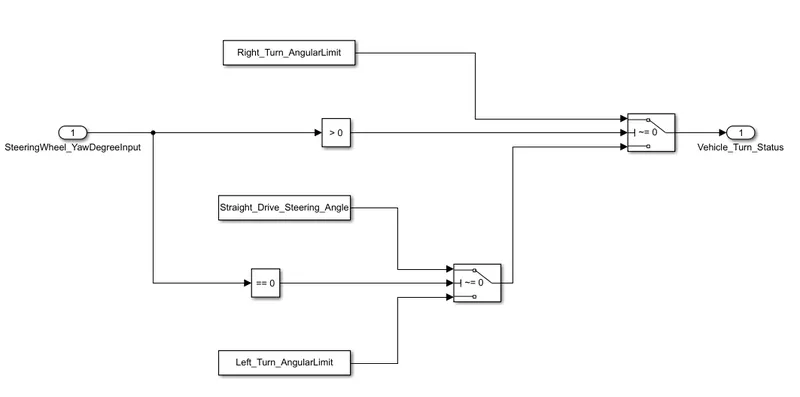
- Steering wheel input as yaw rate (Signal name: SteeringWheel_YawDegreeInput) is the input for this system.
- This is compared against 3 angular values, one each for a left turn, right turn & straight drive (Calibration Values: Right_Turn_AngularLimit, Left_Turn_AngularLimit, Straight_Drive_Steering_Angle) to say which specific direction the steering wheel is turning towards.
- Use switch blocks to compare & develop this requirement. Keep this requirement in a subsystem & the output of this requirement is a local signal (Signal Name: Vehicle_Turn_Status).
Requirement-2
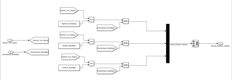
- Keep this requirement as a separate subsystem. Inputs to this requirement are a local signal from requirement 1 (Signal Name: Vehicle_Turn_Status) & an input signal from the camera (Signal Name: CameraInput_RoadSign), which confirms the occurrence of a road sign.
- Signal Vehicle_Turn_Status is compared against calibration values (Calibration Values: RightTurn_RoadSign, LeftTurn_RoadSign, Straight_RoadSign), if each of them is found equal, then each of the three corresponding output is compared against the camera input signal,
- Using a logical operator block, only one among them is finally given as an output signal (Signal Name: Vehicle_Direction_Indicator).
2. Tag the requirements to the simulink model; tagging requirement 1 & requirement 2 to their corresponding subsystems is fine.
- Create a word file shown below containing details of both requirements and save this file in the same folder of your MATLAB model.
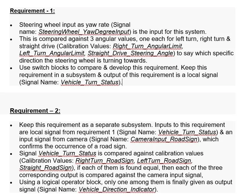
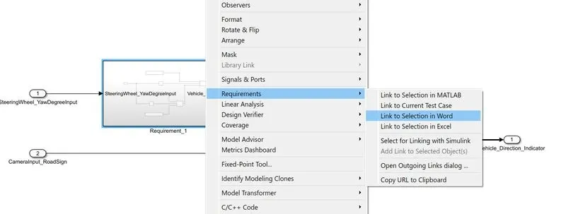
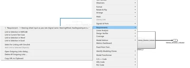
- Select the desired requirement in the file shown below and minimise the word file, Right click on subsystem whose tagging is to be done -> Requirements -> Link to selection in Word.
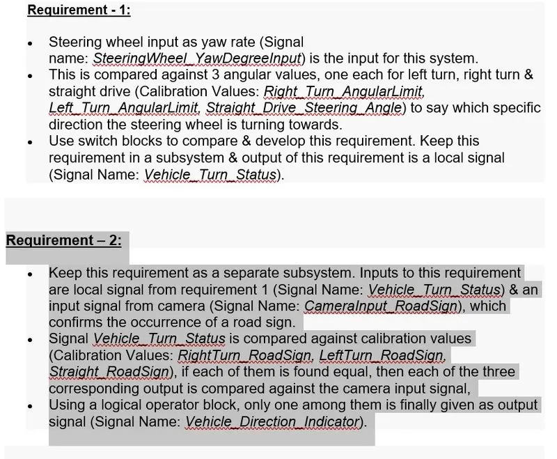
- Tagging will be done and by selecting subsystems it will appear with a coloured background shown below.
3. MBD compliant changes, Data Dictionary creation, S function generation and code generation is an added advantage, and that is not scope of this project.
(a) MBD compliant changes
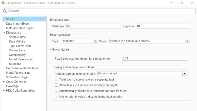
- Click on Modelling -> Model settings -> Solver
- In solver selection -> Type: Fixed-step and Solver: discrete (no continuous states)
- Under Solver details set Fixed step size: 0.01
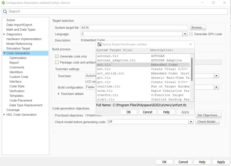
- In code generation -> Browse system target file for Embedded coder
- Apply and OK
(b) Data Dictionary creation
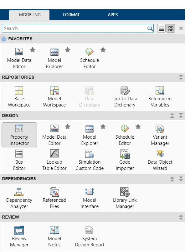
- In simulink model -> modelling -> design -> Link to Data Dictionary
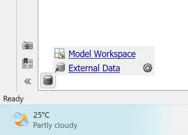
- Window of model properties will pop up -> New -> Create a file name -> Apply OK -> Symbol will appear on the left bottom side shown below.
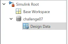
- Click on External Data and new window will pop up with a file name written on left side, selecting that will show down a object with "Design data"
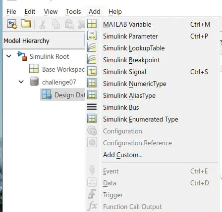
- To add any signal click on Simulink Signal and for adding any constant click on Simulink Parameter
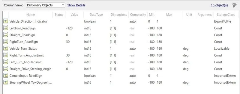
- Below is shown the list of required signals and parameters to be used in this project.
(c) Creation of S block and code generation.
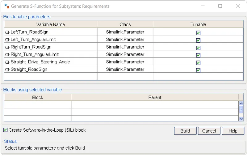
- To create S block -> Right click on subsystem -> C/C++ code -> Generate S function
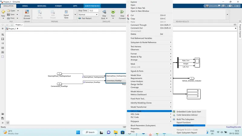
- New window will appear -> Tick mark the block of SIL at bottom and then select Build option.
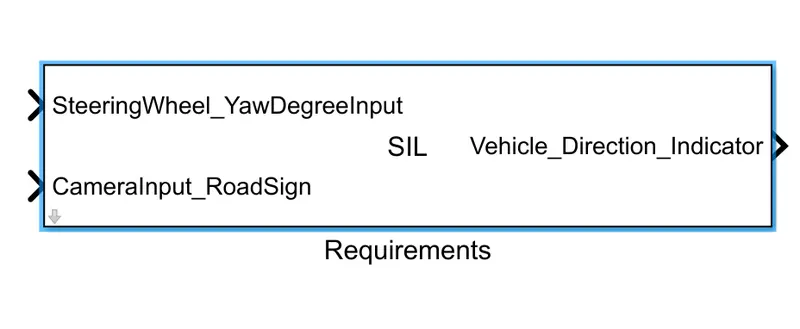
- A model file of S block will be created, which is shown below.
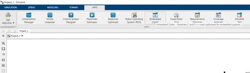
- To generate the code on Title bar -> Apps -> Embedded coder -> Build
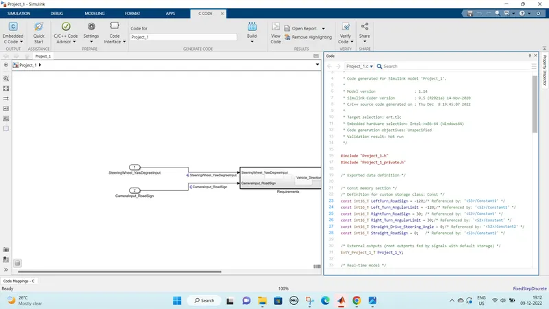
- Multiple code will be generated with extension of .c and .h files. Below is shown the list of generated codes
4. Model Advisor
- On Title bar -> Modelling -> Model advisor -> Window with model name will appear Click OK -> New window will appear having options of By product and By Task
- Tick mark the following options shown below and run the model advisor.
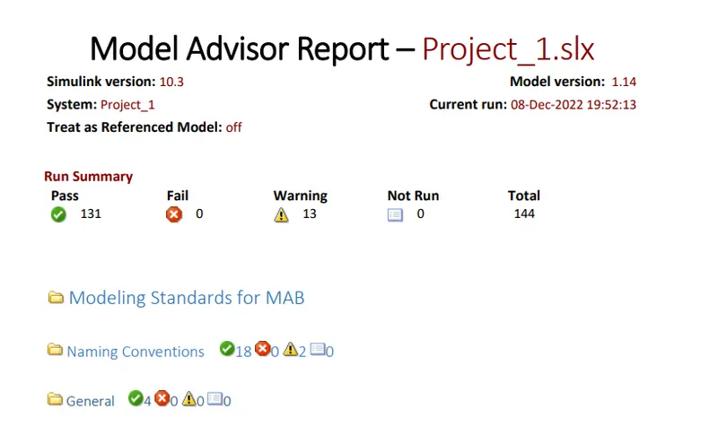
- The report generated by this function is supposed to have errors less than 15. To reduce errors, go through the report and solve the possible errors and generate the report again.
5. Result
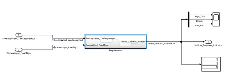
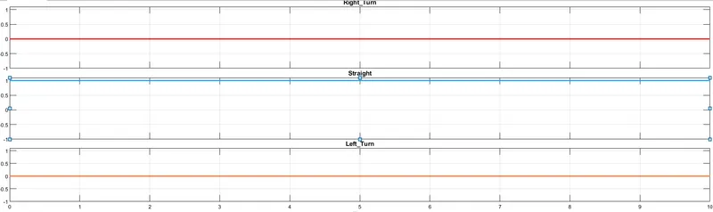
- Result is shown below with display and scope which is showing active for Straight drive because of the condition selection made inside the logic. These results are dependent on the initial values of signals created in Data dictionary.
- For trying different results one can try changing initial value of signal SteeringWheel_YawdegreeInput which is currently set to zero. If the value is made greater than 0 than it will show active for Right side and value less than zero it will show for left.