Project 1 (Mini Project on Vehicle Direction Detection
AIM- The aim of the project is to understand and implement the functional property of Vehicle Direction Detection using model based development technique in MATLAB Simulink.
Vehicle Direction Determination- Vehicle Direction Detection is one of the ADAS feature which is accountable for giving information about the Right/Left turn and use this data for various other smart feature to understand and implement practical features to the ADAS. Like if we use Vehicle Direction Determination with the GPS system then by evaluating the data from road and traffic sign The ADAS can understand vehicle is mooving in the right direction according to the map or not and It alerts the driver if wrong route is taken.
Objective of Mini Project:
- Development of MATLAB Simulink model as per requirement.
- Tag the requirements to the simulink model; tagging requirement 1 & requirement 2 to their corresponding subsystems is fine.
- MBD compliant changes, Data Dictionary creation & code generation is added advantage, and that is not scope of this project.
- If choosing code generation, Storage class for Input signals: ImportedExtern; Storage class for Output signal: Export to File; Storage class for local signals: localizable; Storage class for calibration signals: Const.
- Choose sample time for all signals as 0.01s
The requirement of the projects are to Link the requirement in the word file and can be Tagged using the Requirements option "Link to selection word". I followed the right procedure to develop the model and for code generation, I followed below steps to achileve the Aim of the project.
Step1- To create subsytem and Give signal names as per requirements.
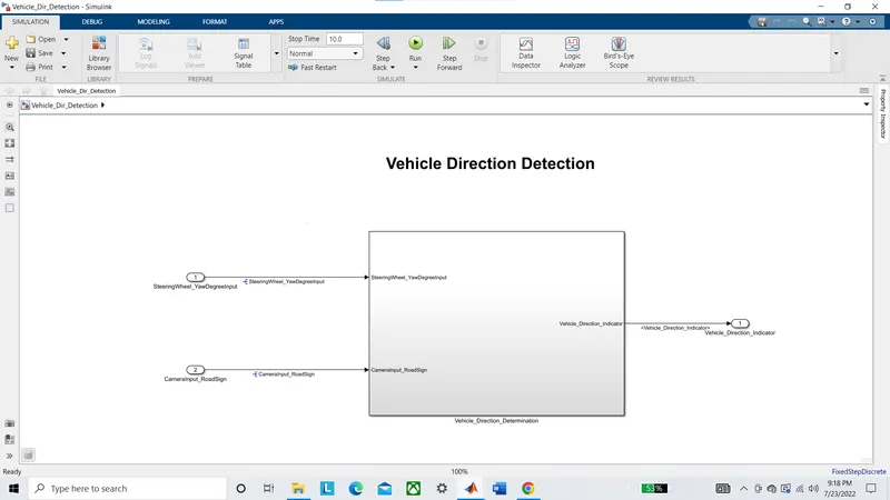
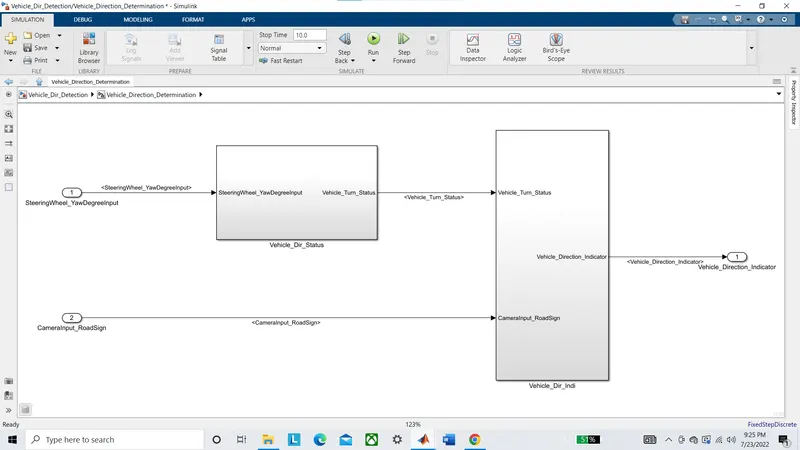
Here we create a Subsystem to implement the Vehicle Direction determination with the inputs...
1. SteeringWheel_YawDegreeInput
2. CameraInput_RoadSign
and output
1. Vehicle_Direction_Indicator
The above inputs are used to implement two requirements from the requirement document. and these two requirements are implemented in the two subsystem under the main system. (Vehicle_dir_Status, Vehicle_Dir_indi)
Step2- Now we implement the logic for the Requiement 1
Requirement - 1:
- Steering wheel input as yaw rate (Signal name: SteeringWheel_YawDegreeInput) is the input for this system.
- This is compared against 3 angular values, one each for left turn, right turn & straight drive (Calibration Values: Right_Turn_AngularLimit, Left_Turn_AngularLimit, Straight_Drive_Steering_Angle) to say which specific direction the steering wheel is turning towards.
- Use switch blocks to compare & develop this requirement. Keep this requirement in a subsystem & output of this requirement is a local signal (Signal Name: Vehicle_Turn_Status).
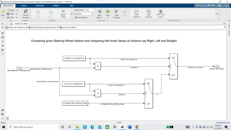
In the first Requirement the Input signal is taken "SteeringWheel_YawDegreeInput" and output signal(Vehicle_Turn_Status) is produced by comparing the Steering yaw angle with the Thresold/Angle_Limit that is stored in the variable names......
1. Right_Turn_AngularLimit
2. Left_Turn_AngularLimit
3. Straight_Drive_Steering_Angle
For the Input in the range between two thresold(Right and Left) the output will be Straight Drive Angle and beyond that limit the Input is compared with the thresold/limit_angle and the corresponding Right and Left angle limit is taken as output if the input exceeds beyond these limit.
Step3- Now we implement the logic for the Requiement 2.
Requirement – 2:
- Keep this requirement as a separate subsystem. Inputs to this requirement are local signal from requirement 1 (Signal Name: Vehicle_Turn_Status) & an input signal from camera (Signal Name: CameraInput_RoadSign), which confirms the occurrence of a road sign.
- Signal Vehicle_Turn_Status is compared against calibration values (Calibration Values: RightTurn_RoadSign, LeftTurn_RoadSign, Straight_RoadSign), if each of them is found equal, then each of the three corresponding output is compared against the camera input signal,
- Using a logical operator block, only one among them is finally given as output signal (Signal Name: Vehicle_Direction_Indicator).
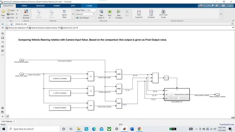
The input to this subsystem is
1. Vehicle_Turn_Status
2. CameraInput_RoadSign
and output is
1. Vehicle_Direction_Indicator
The Vehicle_Turn_Status signal is again compared with the Calibration value i.e. the Road signs which is stored in the memory by camera system. and the logical output to the Right, Left and Straight switch status is re-evaluated(signal is generated only if camera input is True) with the CameraInput_RoadSign and output of these signals are then propagated by using a multi-port switch. the Final_selection subsystem is activated only if one of the status signal is activated and these is implemented by using enable subsystem.
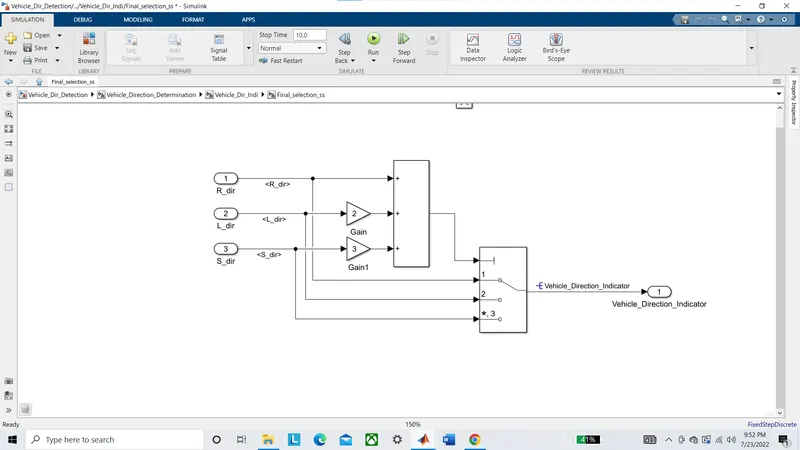
The gain value is multiplied by the signal to select the corresponding signal in multi-port switch. and the output of the switch is taken as Vehicle_Direction_indicator.
Step4- Make SLDD by creating new DD in the model property. then add all variables and signals and parameters according to the data given in the requirement and save the changes.
The SLDD is accessed in the model explorer and all required data is added in this Tab. we further introduce new localised signal to improve the readability of generated code.
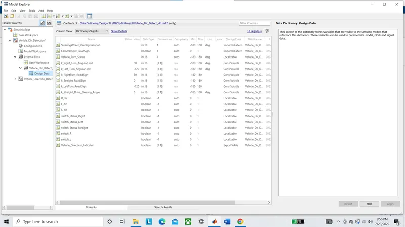
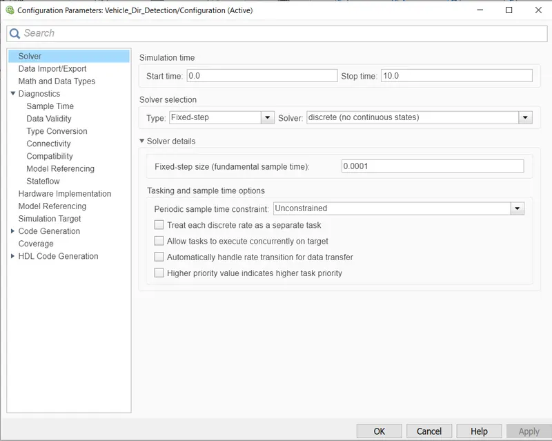
Step5- Now we edit some model configuration in the model setting to follow basic MAAB guidlines.
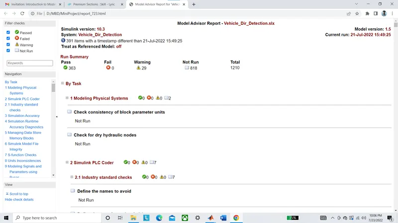
Step6- Now run Advisor tool and remove all errors and try to reduce all warnings for the selected tests.
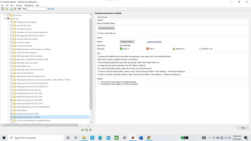
Run the test and remove errors and reducing warnings are the general procedure for model based development. after this generated report need to save in the same folder.
Step7- Now click ctrl+B to generate C code.
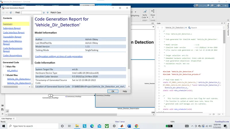
The code and Code Genration report is succesfully generated and saved in the folder to the current directory.