Mini Project on Vehicle Direction Detection
Aim: To Develop and Analysis the Working of Model for Vehicle Direction Determination by use of Matlab and Simulink.
Objectives:
To develop the model for Vehicle Direction Determination as per the following requirements.
Requirement1:
- Steering wheel input as raw rate (Signal_Name:SteeringWheel_YawDegreeInput) is the input for the system.
- This is compared against the 3 angular value, one each for left turn, right turn and straight drive(Calibration Value:Right_Turn_AngularLimit,Left_Turn_AngularLimit,Straight_Drive_Steering_Angle) to specify the direction of steering wheel movement.
- With the help of switch block develop the requirement, and the output from this subsystem will be the local signal(Signal Name:Vehicle_Turn_status)
Requirement 2:
- Output(Signal Name: Vehicle_Turn_status) from above requirement, will be thefirst input for this subsystem as well as CameraInput_RoadSign will be its second input. CameraInput_RoadSign will confirms the occurance of the road sign.
- (Signal Name: Vehicle_Turn_status) will be compared with calibration value(Signal Name:RightTurn_RoadSign, LeftTurn_RoadSign and Straight_RoadSign).If each of them found equal thaneach of the corresponding output signal will be compared against CameraInput_RoadSign and will be output (Signal Name:Vehicle_Direction_Indicator).
Introduction:
A direction determination system is one of the useful and have multiple feature can be incoprated in Autonomous Driving and Advanced Driver Assistance System. This features mainly identifies the direction the vehicle is taking by use of camera input.Based on the reading of the camera, seprate values will be assign for the vehicle for left turn, right turn and straight drive condition and provides the indication to the driver whether s/he is moving in the recommended direction or not.Sensor attached to the steering column can be used to find the changes in the position of the steering wheel. This change is compared against the occurance of the sign in the road with the help of Camera.If condition statisfy , it will warn /indicate the driver whether s/he is moving in the desired direction of not.
Logic:
- If steering wheel makes the positive angle ,Steering wheel angle(Yaw degree)>0 , we can consider it as a Right Turn.
- If Steering wheel makes the neagtive angle,i.e Steering Wheel angle(Yaw Degree)<0, we can consider it as a Left Turn.
- When Steering wheel doesnot makes any angle i.e. Steering wheel angle(Yaw Degree)==0, we can consider it as a straight drive.
- All the above occurance is compared against the Camera Input.
Different Signal and Calibration Value:
| Signal | Type | Data Type | Dimension | Min | Max | Initial Value | Unit |
| SteeringWheel_YawDegreeInput | Input | int16 | 1 | -180 | 180 | - | Deg |
| CameraInput_RoadSign | Input | Boolean | 1 | 0 | 1 | - | - |
| Vehicle_Turn_Status | Local | int16 | 1 | -180 | 180 | - | Deg |
| Right_Turn_AngularLimit | Calibration | int16 | [1 1] | -180 | 180 | 30 | Deg |
| Left_Turn_AngularLimit | Calibration | int16 | [1 1] | -180 | 180 | -120 | Deg |
| Straight_Drive_Steering_Angle | Calibration | int16 | [1 1] | -180 | 180 | 0 | Deg |
| RightTurn_RoadSign | Calibration | int16 | [1 1] | -180 | 180 | 30 | - |
| LeftTurn_RoadSign | Calibration | int16 | [1 1] | -180 | 180 | -120 | - |
| Straight_RoadSign | Calibrtion | int16 | [1 1] | -180 | 180 | 0 | - |
| Vehicle_Direction_Indicator | Output | Boolean | 1 | 0 | 0 | - | - |
Simulink Model.
Top Level Model:
Figure 1 shows the Top level model for Vehicle Direction Detection which contains two input signal i.e SteeringWheel_YawDegreeInput and CameraInput_RoadSign. Based on the above input signal output signal i.e Vehicle_Direction_Indicator is generated.
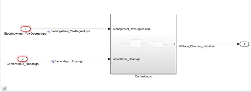
Figure1: Top level Model for Vehicle Direction Determination System
Sub-Level Model:
The sub level model for the Vehicle Direction Determination System is shown in the figure 2. The input signal for Requirment1 is SteeringWheel_YawDegreeInput and Input signal for Requirement2 will the the output from Requirement 1 i.e. Vehicle_Turn_Status and CameraInput_RoadSign. The output from the Requirement 2 will be the final output i.e.Vehicle_Direction_Indicator from the system.
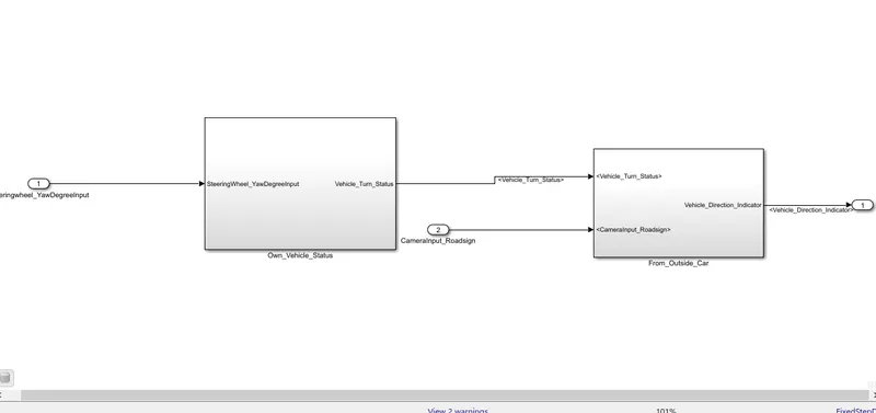
Figure 2: Sub-Level Model for Vehicle Direction Determination
Requirement1:
Figure 3 shows the block arrangement for requirement.The input for the requirement 1 is the SteeringWheel_YawDegreeInput which is send to the switch block and based on the input, it is compare whether it is greater than 0 less than 0 or zero. Then with the help switch block, an local output signal is obtained which is fed to the requirement 2. The input signal is compared against the calibration value i.e. Right_Turn_AngluarLimit,Left_Turn_AngularLimit and Straight_Drive_Steering_Angle.Saturation block is used to limit the angular input between Right_Turn_Angularlimit and Left_Turn_AngularLimit i.e. between 30-(-120).
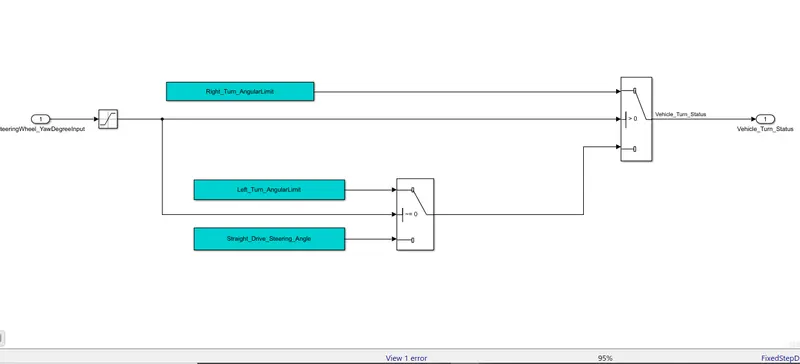
Figure 3: Simulink Block arrangement for Requirement1.
Requirement2:
Figure 4 shows the simulink block arrangement for requirement 2. The input from the requirement 1 is compared against calibration value i.e. RightTurn_RoadSign, LeftTurn_RoadSign and Straight_RoadSign. by use of relational block.Now output from the relational block is again fed to a logical block whose input is CameraInput_RoadSign and output from the relational block.Based on the occurance of road sign(CameraInput_RoadSign), it will provide the corresponding output signal which is Vehicle_Direction_Indicator.
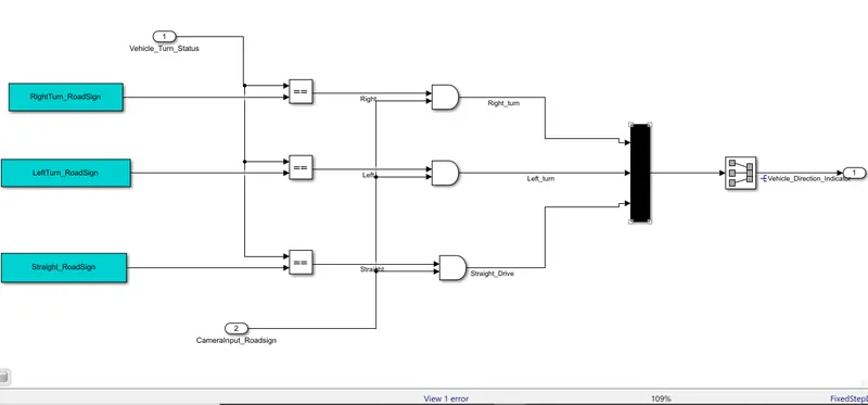
Figure 4: Simulink block arrangement for requirement 2.
Steps performed:
- Once the model is developed, Simlink Data Dictionary was created as per above mentioned table.
- Then the model is run for certain time interval. During simulating the model No error was detected so the developed model works fine.
- To Validate the model,Model In Loop (MIL) Testing and Software In Loop(SIL) Testing.
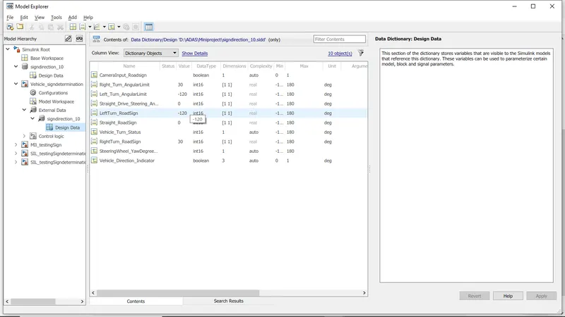
Figure shows the SLDD used for above model:
Model Testing/Validation
a) Model in Loop (MIL) Testing
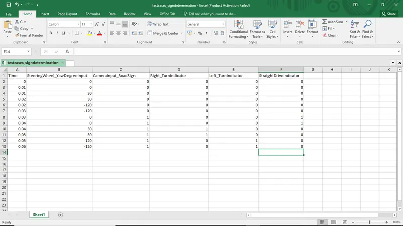
- Test cases are made as per the model in excel.
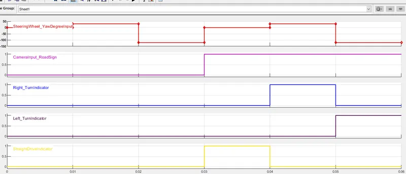
- Those cases are imported and converted to signal by use of Signal builder block.
- After making the suitable connection and simulation time. The model is simulated.
- To understand whether is working fine or not, Output as described in signal builder and output from the model is subtracted and the output from the subtraction is observed through the scope for different time interval.
- Since the output in the scope was found to be Zero. Our model works fine.
Test Cases in Ms Excel:
Test caes imported in Signal Builder
Test cases subsystem:
Model In Loop(MIL) Template:
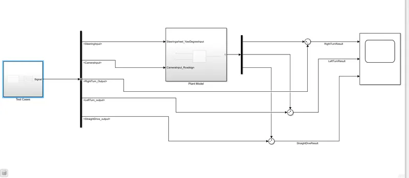
Now the whole system is simulated for 0.06 sec and following result was obtained.
Result:
As we can observe that we obtain zero as a subtraction from the output from the model and described output in testcases. Our developed model is validated by using Model in Loop testing.
b)Software In Loop Testing:
Same test cases were used for SIL testing also. Some changes were made for model properties which includes solver setting as Fixed Step , non discontinous solver with a time interval of 0.01. In code generation section the embedded coder was selected for code generation from the model.
Then, the whole model is converted to subsystem. Right click the subsystem and choose block parameter(subsystem). one dialogue box will appear, enable treat as an atomic subsystem and click ok.
Now, again right click the model and goto test harness option. Select create subsytem. One dialogue box will appear, choose source as signal builder and sink as outport. In the same window, goto adanced setting, and choose Software in Loop option and click ok. It will take some time and SIL harness model will appear. The detailed for the porcess is shown in the figure. The test cases can be imported from excel sheet to signal builder.
After doing this, click on the test harness model. Import the test cases by the help of signal builder and make suitable connection and perform SIL test. The SIL test model is shown below:
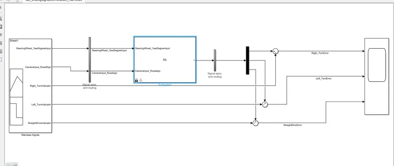
Now run the model and observe the result in the scope for different time interval.
Result:
As seen in the scope , subtraction from output of SIL block and descriped output is zero we can say that the model is valided by use of Software in Loop testing.
Conclusion:
The model has been developed as per the requirement. The model was also valided by the use of technique called as Model in Loop and Software in Loop testing.Based on both testing, the developed model works fine.