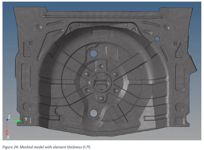
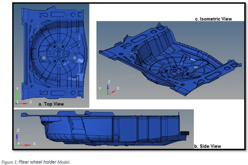
Meshing of Rear Wheel Holder in Hypermesh.
Objective:
- To extract the mid surface of ‘Rear wheel holder’.
- To mesh the “Rear wheel holder” as per given quality criteria.
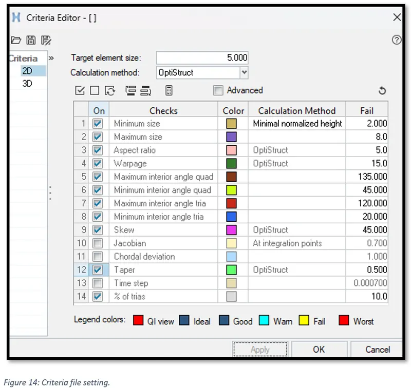
Target Element Length = 5 Units
|
S.No. |
Quality Criteria |
Value |
|
1 |
Aspect Ratio |
5 |
|
2 |
Skewness |
45 |
|
3 |
Warping |
15 |
|
4 |
Taper |
0.5 |
|
5 |
Min. Length |
2 Units |
|
6 |
Max. Length |
8 Units |
|
7 |
Min angle Quad |
45 |
|
8 |
Max angle Quad |
135 |
|
9 |
Min angle Tria |
20 |
|
10 |
Max angle Tria |
120 |
|
11 |
Tria % |
10 |
- Assign the thickness to the meshed model.
Introduction:
In the project we are required to mesh a ‘Rear wheel holder’. Firstly, we will extract the mid surface of the ‘Rear wheel holder’. Secondly, we will 2D mesh the mid surface as per the given quality criteria. Finally, we will assign the thickness to the mesh.
In general, 2D meshing is used for parts having a width / thickness ratio > 20. And we extract mid surface because it represents the geometry appropriately and makes 2D meshing continent. But for a geometry of variable thickness, 2D meshing would lead to higher approximation.
Steps taken:
1) Analysing the ‘Rear wheel holder’ model.
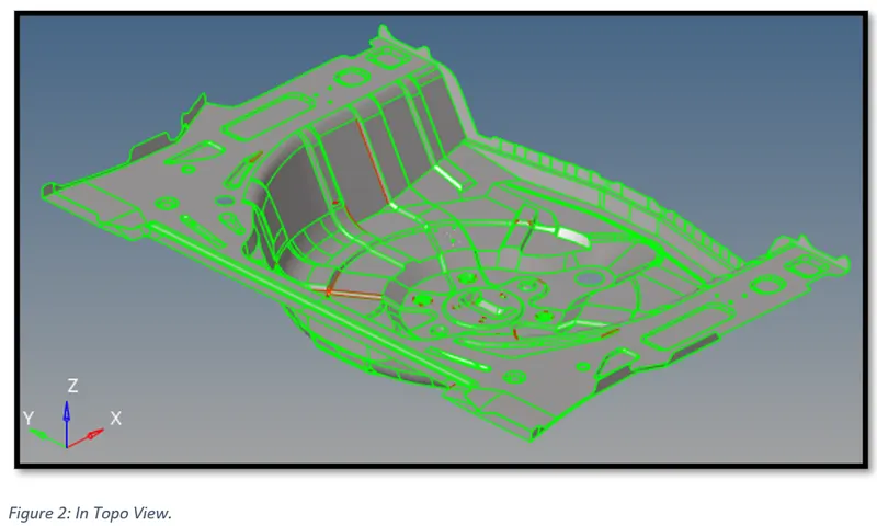
With Topo view on, we can see that it is a shell model and has no solids. In some areas we can also observe some red feature lines dipecting either missing, detached surfaces or duplicated surfaces.
2) Geometric Clean-up.
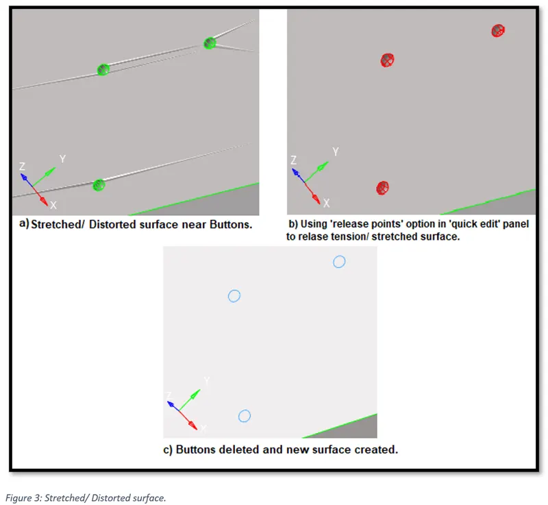
In Fig. 3, we have resolved the stretched surfaces or surfaces in tension by using ‘release points’ option. And then deleted the Buttons (small hemispherical surfaces).
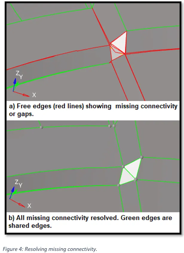
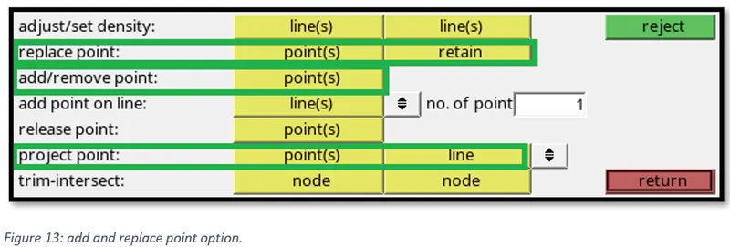
In fig. 4, we have free edges (in red) showing missing connectivity. This is resolved by deleting the missing surfaces, joining the points using the ‘replace point’ option in ‘quick edit’ panel and deleting and recreating the distorted surfaces using ‘filler surf’ in ‘quick edit’ panel.
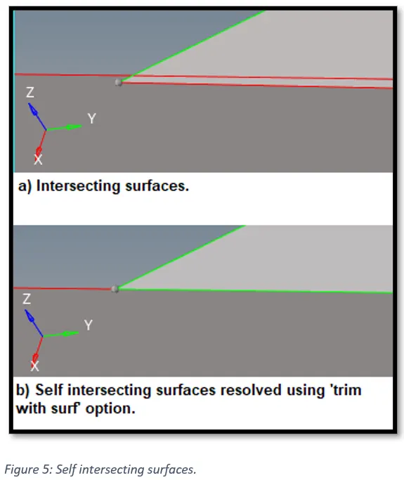
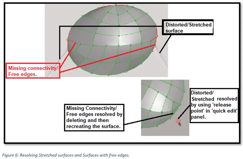
In fig 6, we can see that the hemispherical surface has created stretched surface and there are some missing connectivity also depicted in red. The stretched surface is resolved using ‘release point’ option by going to, quick edit -> release point -> click on the point you want to release.
Missing connectivity is resolved by ; deleting and recreating the surface using ‘skin’ in ‘surface panel’, toggling the red feature line or by using ‘replace’ or equivalence’ option in ‘edge edit’ panel.
3) Extracting the mid surface.
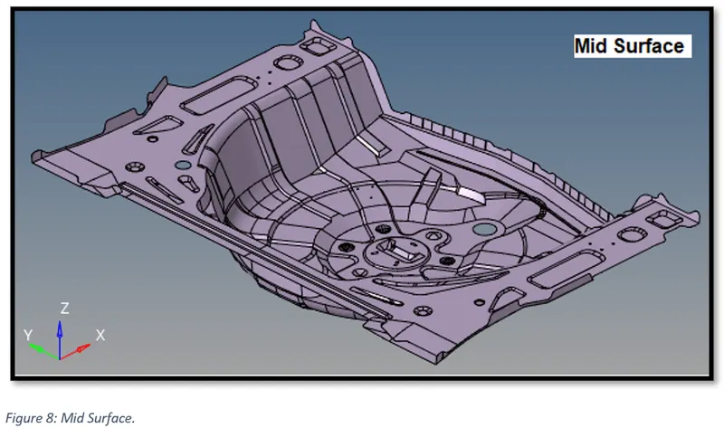
To extract the mid surface of the model, firstly we need to perform the geometric clean-up i.e. simplifying the geometry by removing small fillets, unwanted feature lines etc. This will aid in extracting the mid-surface easily.
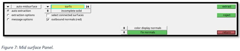
Now Go to, Geom -> Mid surface -> select the surfaces -> Click on extract
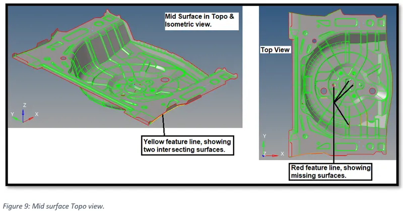
From figure 9, we can see that the mid surface has some free edges (Red feature lines) depicting missing surface and non-manifold edges (yellow feature lines) occurring at T-intersection.
To resolve this, we need to create missing surfaces, remove the duplicate surfaces and T-intersection.
We can use filler surf to create missing surface, reflect to create surfaces which are symmetric, equivalence to remove non-manifold edges etc.
To combine free edges; toggle, or create and replace points option can be used.
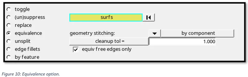
We can use equivalence to remove non-manifold edges.
To use equivalence, go to, Geom-> edge edit -> equivalence
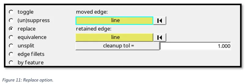
To use replace, go to, Geom-> edge edit -> replace
To use ‘toggle’, go to, Geom -> quick edit -> toggle
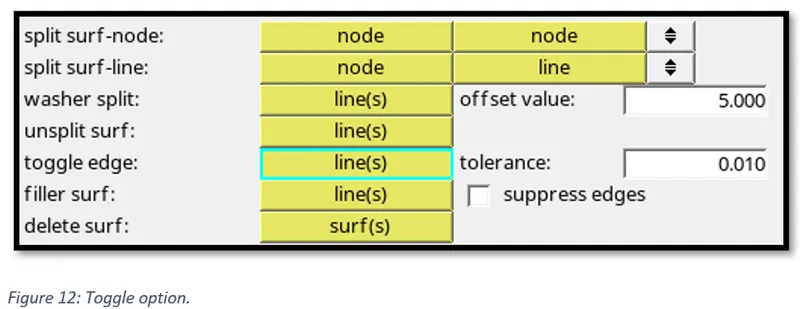
To use, ‘add and replace’ points, go to, Geom -> quick edit
After combining the free edges, the combined surfaces are joined by shared edges (green) as shown below.
4) Meshing the Mid-surface.
Setting up criteria file setting as per given parameters.
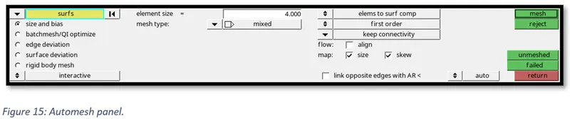
Now, go to, 2D -> Automesh -> select all the displayed surfaces -> click on mesh
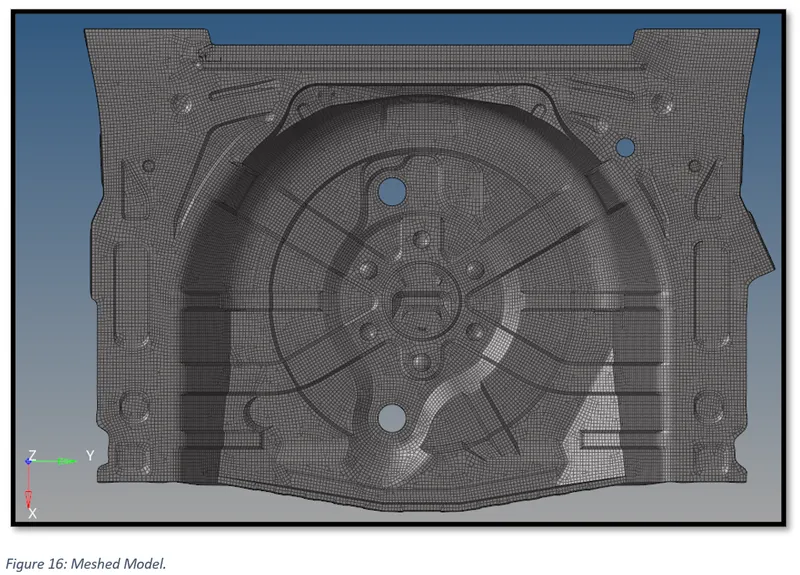
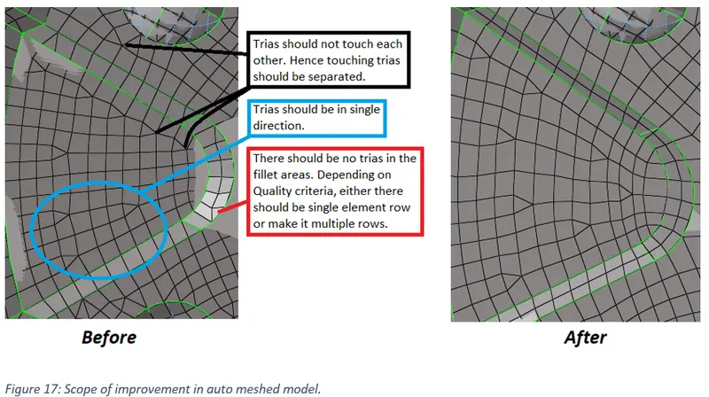
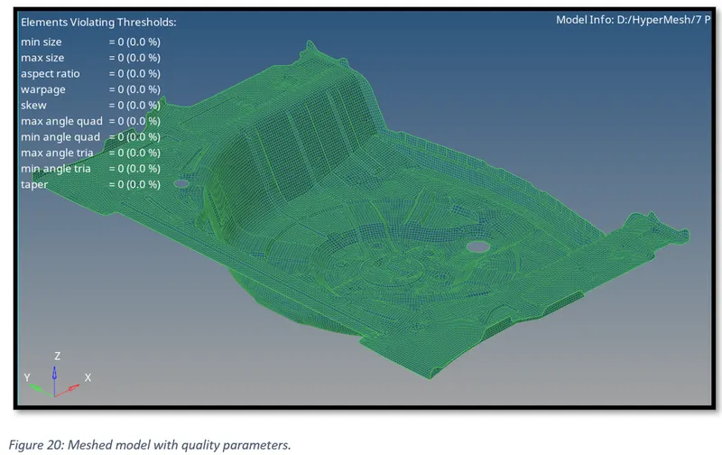
5) Meshed model conforming quality criteria.
To check quality parameters, go to, 2D -> quality index.
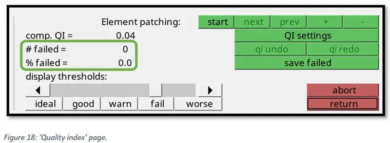
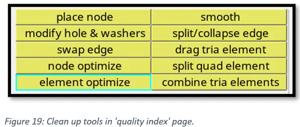
By using clean up tools we can resolve failed elements.
6) Assigning thickness to the Mid-surface.
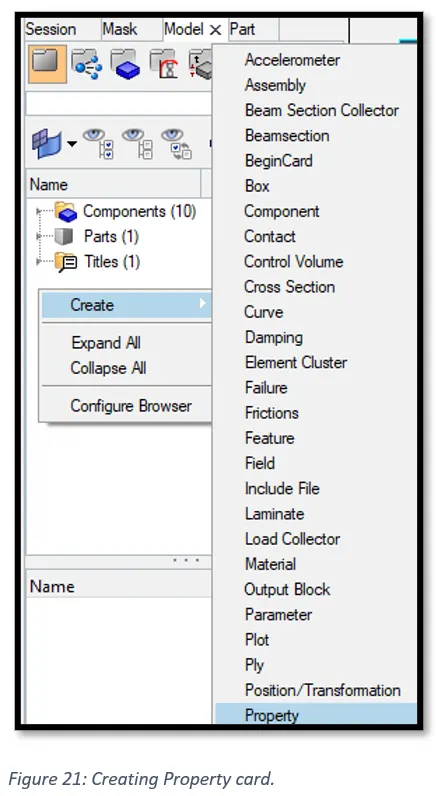
Under the model tab, right click and go to, Create -> Property.
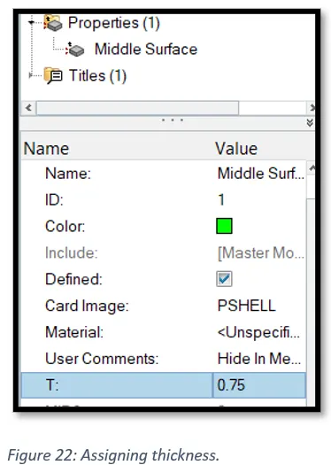
Rename the property card and assign the thickness as per the model thickness. For this model element thickness as 0.75.
Now, right click on the component and click on ‘Assign’ to assign the property card containing element thickness.
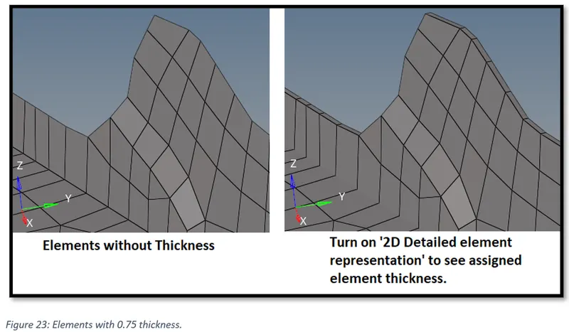
Finally, we can see meshed inner door panel model with element thickness 0.75.